Lust VF1000M TR User manual

1
SMARTDRIVE - VF1000M/VF1000L,TR/S58
± 10 V Reference Input
Technical Controller
stop
return start
enter
VAL
Hz
SMART
CARD
PI
Type description TR From page 2
S58 From page 14
Important: This description does not replace the VF1000M and
VF1000L Operation Manuals. In commissioning, and
when performing other work on the inverter, be sure to
follow the instructions, and in particular the safety
instructions, given in the relevant manual.
EN

2
SMARTDRIVE - VF1000M/VF1000L,TR
1 Overview
± 10 V reference input (FSIN2):
• Analog input with automatic direction of rotation selection
• Additional offset input for 1st analog input (FSIN)
• High-resolution analog input (16-bit)
Technical controller:
• PI controller for process control, e.g. pressure, temperature,
flow, winding drive, etc.
Note: All manufacturers’ declarations and acceptances issued
for the standard series are also applicable to theVF1000M,
TR and VF1000L, TR frequency inverters.
When the TR version is selected the following additional
versions are not possible:
VF1000M C2 and C8
VF1000L C1, C2, and OP1 ... OP10
VF1000L,HF
The variant described here is based on the standard
software:
V1.2 for VF1000M
V1.6 for VF1000L
Expanded functions in the standard software are not
automatically adopted into the software of theTR version.
The current injection (55_ISEL = 3,4,5) is not selectable.
3
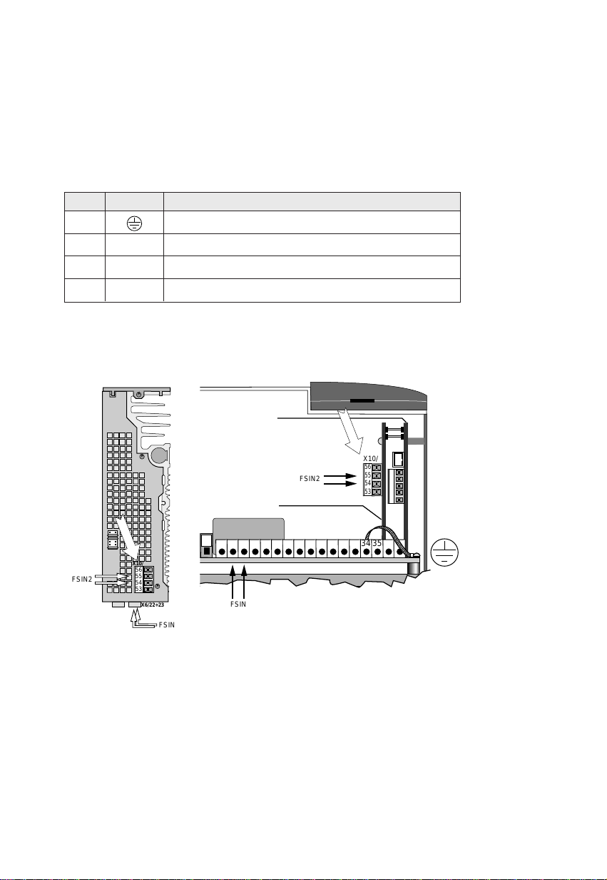
2 Electrical Connections
The typeTR inverters are fitted with an additional terminal strip (X10).
The terminal assignment and position sketches are shown below.
X10/ Label Description
53 Termination pointforprotective earth
54 GND Frame reference pointfor 10V reference
55 FSIN2 ±10Vinput (2ndanaloginput)
56 UR 10Vreferencefor referenceinput
Position sketches:
VF1000M,TR VF1000L,TR
+
2122232425 26272829 30313233 3637
MC-Print
TR-Print
,,,,,
,,,,,
,,,,,
,,,,,
,,,,,
,,,,,
,,,,,
@@@@@
@@@@@
@@@@@
@@@@@
@@@@@
@@@@@
@@@@@
ÀÀÀÀÀ
ÀÀÀÀÀ
ÀÀÀÀÀ
ÀÀÀÀÀ
ÀÀÀÀÀ
ÀÀÀÀÀ
ÀÀÀÀÀ
,,,,,
,,,,,
,,,,,
,,,,,
,,,,,
,,,,,
,,,,,
@@@@@
@@@@@
@@@@@
@@@@@
@@@@@
@@@@@
@@@@@
ÀÀÀÀÀ
ÀÀÀÀÀ
ÀÀÀÀÀ
ÀÀÀÀÀ
ÀÀÀÀÀ
ÀÀÀÀÀ
ÀÀÀÀÀ
,,,,,
,,,,,
,,,,,
,,,,,
,,,,,
,,,,,
,,,,,
@@@@@
@@@@@
@@@@@
@@@@@
@@@@@
@@@@@
@@@@@
ÀÀÀÀÀ
ÀÀÀÀÀ
ÀÀÀÀÀ
ÀÀÀÀÀ
ÀÀÀÀÀ
ÀÀÀÀÀ
ÀÀÀÀÀ
,,,,,
,,,,,
,,,,,
,,,,,
,,,,,
,,,,,
,,,,,
@@@@@
@@@@@
@@@@@
@@@@@
@@@@@
@@@@@
@@@@@
ÀÀÀÀÀ
ÀÀÀÀÀ
ÀÀÀÀÀ
ÀÀÀÀÀ
ÀÀÀÀÀ
ÀÀÀÀÀ
ÀÀÀÀÀ
,,,,,
,,,,,
,,,,,
,,,,,
,,,,,
,,,,,
,,,,,
QQQQQ
QQQQQ
QQQQQ
QQQQQ
QQQQQ
QQQQQ
QQQQQ
¢¢¢¢¢
¢¢¢¢¢
¢¢¢¢¢
¢¢¢¢¢
¢¢¢¢¢
¢¢¢¢¢
¢¢¢¢¢
3435
56
55
54
53
X10/
FSIN2
FSIN
+
+
+
56
55
54
53
X10/
FSIN2
FSIN
X6/22+23

4
3 Technical Specification
Connection Spezification
FSIN2 Input range + 10 V ... - 10 V
(isolated)
Resolution 16 Bit
Input resistance 150 kΩ
Dielectric strength ± 30 V
Sampling time 8 ms
UR Reference voltage 10 VDC ± 3 %
Load capacity 15 mA max.,
short-circuit-proof
Terminal X10 Terminal cross-section max. 2.5 mm²
3.1 Input FSIN2
The FSIN2 can be used as an additional reference input with the
following functions:
Parameter Setting Function
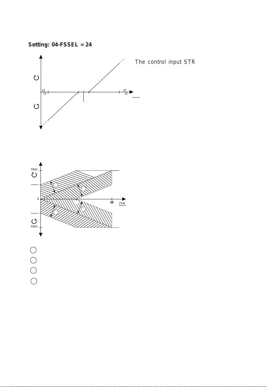
04-FSSEL 24 FSIN2 = ± 10 V reference input with automatic
direction of rotation selection
Hysteresis = ± 150 mV, STR input
as hardware enable
04-FSSEL 25 FSIN2 = 0 ... 10 V reference input
04-FSSEL 26 FSIN2 = offset to FSIN (see example)
+ 10 V at FSIN2 => add FMAX
2
- 10 V at FSIN2 => subtract FMAX
2
Example: FMAX = 50 Hz; FSIN = 5 V; FSIN2 = + 5 V
FOUT = 25 Hz (from FSIN) + 12.5 Hz (from FSIN2)
= 37.5 Hz
5
,
0
10
FMAX
FMAX
FSIN
V
,
,
,
FMAX
2
FMAX
2
12
4
3
5
Setting: 04-FSSEL = 24
The control input STR is
the hardware enable. The
direction of rotation is
automatically selected.
Setting: 04-FSSEL = 26
STR = active
STL = active
1 FSIN 2 = 0 ... + 10 V
2 FSIN 2 = 0 ... - 10 V
3 FSIN 2 = 0 ... + 10 V
4 FSIN 2 = 0 ... - 10 V
-1,0 -0,15
0
+0,15 +1,0
F(Hz)
F(Hz)
FSIN 2
V

6
3.2 Technical Controller
The technical controller in theVF1000M andVF1000L controls process
variables such as pressure, temperature, flow rate, jump, etc. It is not
suitable for dynamic process variables such as rotational speed.
3.2.1 Actual Value Channel
76-CONFI Function
0VAL Technical controllerinactive,functionofFSIN2 with
04-FSSEL= 24/25/26
1 Analoginput FSIN
(0 ...10V, 2 ...10 V, 0 ...20 mA, 4 ...20 mA)
2 AnaloginputFSIN2 (±10V)
3 Frequency input (0 ...1 kHz) via FSIN
4 Frequency input FSIN (0 ...10 kHz) via FSIN
5 PWM input (0 ... 100%) via FSIN
6 Serialinterface
Note: Input FSIN can only be assigned once.
3.2.2 Reference Channel
04-FSSEL Referenceselector
0VAL Analog input, 0 ...10V, 2 ...10V, 0 ...20 mA, 4 ...20 mA
3 FSIN as frequency input 0 ... 1 kHz
4 FSIN as frequency input 0 ... 10 kHz
5 FSIN as PWM input 20 ... 100%
6 FSIN as PWM input 0 ... 100%
7 FSINinactive,referenceviaKP100(CTRL menu)
8 Referencevia interface
9 to 16 Reference inputvia fixed frequencies (seeOperationManual)
17to22 CorrectionofanalogreferenceviaS1IND/S2IND
(MOPfunction active)
23 Analog input,directionof actioninverted
24 Analog inputFSIN2, ±10V
25 Analog input FSIN2, 0 ...10V
Note: For more details concerning the functions of analog input FSIN
refer to the relevant Operation Manual.
7
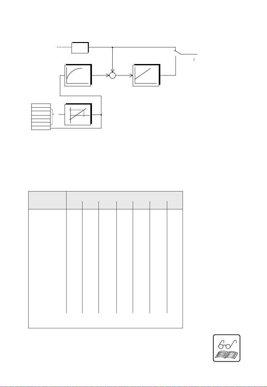
76-CONFI = 0
PI controller
90-ABW 60-FOUT
77-KP, 78-TN
12-F
84-FIST
76-CONFI = 0
Reference
83-FST2
xmax
HI
LO
y/Hz
Scaling
Actual value
1
2
3
4
5
6
xy
76-CONFI
04-FSSEL
Filter
3.2.3 Block Diagram
3.2.4 Combination Options of the Reference and
Actual Value Channels
Reference Actual value 76-CONFI =
04-FSSEL = 0 1 2 3 4 5 6
0X X X
3X X X
4X X X
5X X X
6X X X
7 X X X X X X X
8 X X X X X X
9 - 16 X X X X X X X
17 - 22 X X X
23 X X X
24 XX X X XX
25 XX X X XX
X = permissible combination
Note: Parameter 30-FF7 cannot be selected as a reference.
8
The following diagnostic parameters are available to check the
optimum setting of the controller:
Parameter Display value Function
60-FOUT Instantaneous[Hz] Current outputfrequency(see block diagram)
84-FIST Instantaneous[Hz] Currentlyscaledactualvalueupstream of
controller
37-OVER Fixed [Hz] Maximumoutputfrequency afterstart
40-UNDER Fixed[Hz] Minimumoutputfrequency afterfrequency
maximum
65-STIME Fixed [Hz] Risetimeto pointwhere actualvalueis equal
toreference for firsttime
90-ABW Instantaneous [Hz] Currentamountof controldifference
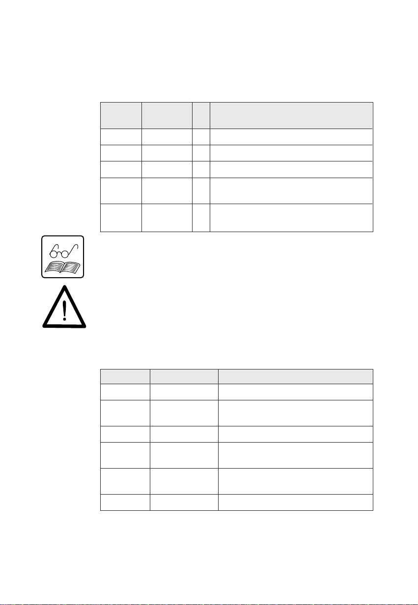
Controller Parameters
Theparameters set out belowareavailable for setting and optimization
of the controller:
Parameter Manipulating VAL Function
Range
77-KP 0.1 ... 10 0.5 Gain (P-component), adjustable online
78-TN 0 ... 65 [s] 0 Lag time (I-component), adjustable online
30-FF7 0 ... 999 [Hz] 0 Control start frequency
93-LEVHI 0 ... 400 [Hz] 50 Scaling of actual value signal, input optimizes
manipulatingrange(upperlimit)
88-LEVLO 0 ... 400 [Hz] 0 Scaling ofactual value signal,input optimizes
manipulating range (lower limit)
Note: Save 77-KP and 78-TN with 71-PROG = 5.
Important: With version TR parameters 93-KOMP, 88-PSW1, 83-
SIOW and 84-SIOT are no longer required.

9
Diagnostic parameters graph (step response of a control loop):
Prozeßgröße
(Hz)
t (s)
37-OVER
40-UNDER
65-STIME
Reference step-change
Output freq.
Note: Parameter 65-SINT for ON delay of control inputs in
VF1000M no longer required.
Process
variable (Hz)

10
3.3 Commissioning the Controller
1) Connect the motor and control cables and set the motor
characteristic as set out in the Operation Manual.
2) Connect the actual and reference value signals to inputs FSIN
and FSIN2, observing the existing signal type.
Important: Only voltage signals can be fed in at input FSIN2.Current
signals and digital signals can only be fed in at FSIN.
3) Set parameter 04-FSSEL to the available reference signals.
4) Set the desired actual value signal with parameter 76-CONFI.
5) Optimize the resolution of the actual value signal with
parameters 93-LEVHI and 88-LEVLO.
6) As necessary, set the reference and actual value filters with
parameters 67-FST and 83-FST2 (see “Optimizing the
Controller”).
7) Set and optimize the control parameters 77-KP and 78-TN (see
“Optimizing the Controller”).
3.4 Optimizing the Controller
If current or voltage ripple occurs on the actual and reference signals,
it can be damped with the aid of low-pass filters.The time constants
of the filters can be set as follows:
Parameter Setting VAL Function
67_FST 0 ... 4 2 Referencefilter
83_FST2 0 ... 9 2 Actual value filter
Setting:
67-FST 01 2 3 4
83-FST2 01 2 3 4 5 6 7 8 9
Filter time 0 8.2 24.6 57.3 123 254 0.52 1.04 2.09 4.18
Dim. ms s
This manual suits for next models
3
Table of contents
Other Lust Controllers manuals


Popular Controllers manuals by other brands

Digiplex
Digiplex DGP-848 Programming guide

YASKAWA
YASKAWA SGM series user manual

Sinope
Sinope Calypso RM3500ZB installation guide

Isimet
Isimet DLA Series Style 2 Installation, Operations, Start-up and Maintenance Instructions

LSIS
LSIS sv-ip5a user manual

Rockwell Automation
Rockwell Automation 1769-L31 installation instructions


