Innotech HT-F580 Series User manual

HT2.002.022SS
HT-F580 Serial Fixed UHF RFID Readers
User Manual
(V2.0)

HT2.002.022SS
Contents
PREFACE................................................................................ I
1Reader Introduction..................................................................... 1
1.1 General application ............................................................... 1
1.2 Model Instruction ................................................................. 1
2Reader Parameter....................................................................... 2
2.1 Feature........................................................................... 2
2.2 General requirement .............................................................. 2
2.3 Performance...................................................................... 2
3Communication interface................................................................ 3
3.1 Communication interface picture................................................... 3
3.2 GPIO ............................................................................. 3
3.3 LED Indicator ..................................................................... 5
4Installation ............................................................................. 6
4.1 Precautions....................................................................... 6
4.2 Installation ....................................................................... 6
4.3 Reader Connection................................................................ 7
5Software Connection................................................................ 7
6Routine Maintenance and Repair..................................................... 7
6.1 Common fault analysis and solve method........................................... 8
7Package And Accessary................................................................. 9
7.1 Package.......................................................................... 9
7.2 Accessary list..................................................................... 9
8Transportation and Storage............................................................. 10
8.1 Transportation ................................................................... 10
8.2 Storage.......................................................................... 10
8.3 Waste treatment.................................................................. 11
9After-sale service ...................................................................... 11

PREFACE
Thank you for choosing products fromAerospace Innotech Co,Ltd, we
will be happy to provide you with comprehensive service and technical
support.
This manual will introduce the specific using methods of our reader HT-580
fixed UHF reader to you. In order to operate the readers safely & efficiently and
make full use of the functions & features, please read this manual and the doc. in
CD in details before installation. You will experience the efficiency and
convenience with our products.
When this manual is written it is supposed that readers have basic knowledge
over RFID and computer. The technical words, such as RFID, Radio Frequency &
Ethernet etc in this manual, are not specifically introduced. Please refer to other
reference books or consult our technical department for support.
The following marks would appear in our manual, the meaning are as
below:
Warning
If it disobey the restricted operations or using environments, it might be
harm to human health or damage equipments.
Advice
Follow the advised instructions, the results might be better.
1 Reader Introduction
1.1 General application
HT-F580 fixed uhf reader supportoperation of ISO18000-6C tag like read, write, lock, destroyetc,
working frequency band options: FCC(902MHz~928MHz),CE(865MHz~868MHz)and Chinese
standard(920MHz~925MHz), its reading distance more than 7m and writing distance more than
4m with relevant uhf tags.HT-F580 provides multi communication interfaces, including RS-232,
Ethernet , USB, wiegand interfaces, it also provides expandable 4G or WIFI wireless data
transmission modules .
HT-F580 can be used in all areas where the UHF RFID tags are used for management, such as
warehouse management, access control, parking system, library books management etc.
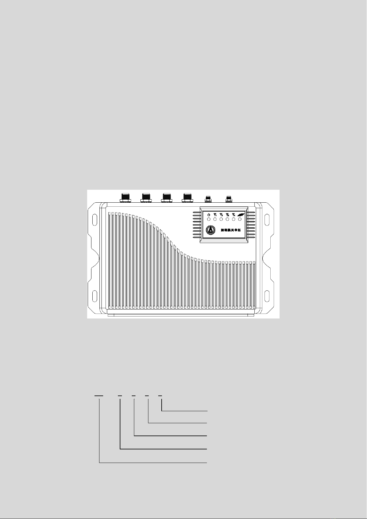
HT-F580 is suitable for wall-mounting installation, reader appearance like below:
Pic 1 Reader Appearance
1.2 Model Instruction
HT - F5 8 0
Serial number:0
Working frequency: 800/900 MHz
Protocol: UHF RFID ISO18000-6C
Products name: Fixed Reader
Company: HTRFID

2 Reader Parameter
2.1 Feature
1) Support ISO18000-6C protocol
2) Frequency band 902-928Mhz FCC, 866-868Mhz CE, 920-928Mhz Chinese standard available,
support fixed or hopping frequency mode.
3) Support TCP/IP, USB, RS232 communication interface
4) Support auto-connection, data filtering
5) Support self-inspection, log management, remote upgrade etc
6) 4G or WIFI wireless data transfer optional
2.2 General requirement
1) Working temperature: -20℃~+60℃
2) Storage temperature: -30℃~+70℃
3) Dimension: 270mm*180mm*45mm
4) Weight:2kg
5) Power supply: Power adaptor inputAC 90~240V,50/60Hz, output DC 12V±20%
6) Power consumption: <24W
2.3 Performance
1) Working frequency: FCC:902MHz~928MHz,channel space: 500kHz
CE: 865MHz~868MHz,channel space: 200kHz
Chinese:920MHz~925MHz,channel space: 250kHz
Frequency hopping or fixed frequency
2) Frequency stability: ±20ppm
3) Output power:+11dBm~+30dBm@50Ω load(default 30dBm), step 1dB
4) Spurious emissions: ≤-36dBm
5) Adjacent channel power leakage ratio: the first adjacent channel≤40dBc;the second adjacent
channel≤60dBc
6) Channel occupied bandwidth:≤250kHz
7) Receive sensitivity: -70dBm

8) Reading distance: >7m
9) Writing distance: >4m
10) Reading speed: 300pcs/s
3 Communication interface
3.1 Communication interface picture
Pic 1
Pic 2
①Power socket: power input, DC 12V±20%
②RJ45 Ethernet
③USB port
④RS232 port
⑤GPIO port : refer to 3.2
⑥WIFI antenna port
⑦4G antenna port
⑧Antenna port 4: TNC connector
⑨Antenna port 3: TNC connector
⑩Antenna port 2: TNC connector
⑪Antenna port 1: TNC connector
3.2 GPIO
1) GPIO

Fig 1 GPIO definition
Pin No.
Name
Signal
Description
1
BUS﹢
OUT
RS485 line-A/
Wiegand data1
2
BUS-
OUT
RS485 line-B/
Wiegand data0
3
GND
--
RS485/wiegand
GND
4
V1
OUT
12V Output1
5
V2
OUT
12V Output2
6
GND
--
GND
7
OUT1
OUT
Relay output 1
8
OUT1
OUT
Relay output 1
9
OUT2
OUT
Relay output 2
10
OUT2
OUT
Relay output 2
11
IN1﹢
IN
IO input﹢
12
IN1-
IN
IO input-
13
IN2﹢
IN
IO input﹢
14
IN2-
IN
IO output-
Pin 4,5,6 are power output, which can output a maximum current of 12V/300mA under software
control, these ports can be power supply for external devices or as normal IO output ports.
When using this interface, please avoid short-circuiting the output interface directly to the ground and
overloading, also pay attention to the circuit and load of the external device, if the external device power
exceeds the limit, the reader will automatically open circuit for protection.

Pin 7,8,9,10 are IO relay output, can execute open/close state under software control, the load of
ports are AC125V/1A or DC30V/1A.
Definition:
“OUT1”corresponds pin 7, 8, as output port 1, normally open state;
“OUT2”corresponds pin 9, 10 as output port 2, normally open state.
Pin 11,12,13,14 are IO input ports for detecting external input of level signals. When detect input level
0.5V~16V state high, and 0~0.5V state low.
Definition:
“IN1”corresponds pin 11,12,as input port 1, “+”(pin 11)is positive,“-”(pin 12) is negative.
“IN2”corresponds pin 13,14,as input port 2, “+”(pin 13) is positive,“-”(pin 14) is negative.
The IO input is internally optocoupled for opto-isolation, so be careful not to apply more than 16V
to the input pins. If you have special needs, please contact our company or the agent to determine the
solution.
3.3 LED Indicator
Pic LED Indicator
The upper panel of the reader has6 LED indicators. Each indicator has a corresponding icon.The meaning
of the icons from left to right is as follows:
Power indicator, red/green, red means power on, green remains unused;
Antenna 1 indicator, red/green, green indicates antenna is enabled, red indicates reader is using the
antenna to transmit signal.
Antenna 2 indicator, red/green, green indicates antenna is enabled, red indicates reader is using the
antenna to transmit signal.
Antenna 3 indicator, red/green, green indicates antenna is enabled, red indicates reader is using the
antenna to transmit signal.

Antenna 4 indicator, red/green, green indicates antenna is enabled, red indicates reader is using the
antenna to transmit signal.
Reading indicator, red/green, green flashing indicates that the reader correctly reads the tags, red
remains unused.
The built-in buzzer of the reader is used to indicate the working status of the reader. When power
on and self-checking successfully, there will be one beep and 2 beeps when reader start successfully.
4 Installation
4.1 Precautions
Reader input power supply is DC 12V±20%, please check your supply voltage range before
installing and ensure that the equipment is grounded!
Any radio transmitting device, including this device, may interfere with the operation of
medical devices that are not properly protected.
The installation location should be protected from rain, moisture and sun, and well ventilated.
Measure and estimate the connection distance between device and control centre.
Pay attention to the length limitation of USB cable and Ethernet cable.
Test well before installation.
When installing multi-readers, pay attention to antenna installation angle and the minimum
distance between antennas to avoid interference.
4.2 Installation
The reader can be installed in desktop or wall mount, and the mounting holes are as shown in Figure
below.
Prepare the mounting holes on wall or brackets based on the reader installing location, and then screw
the reader on wall or bracelets.

Wall Mount installation
4.3 Reader Connection
The readerand thePC canbe connected through anetwork port(TCP), USBand a serial port(RS232);
the reader and the antenna are connected by an RF cable, and the RF cable connector uses a TNC male.
TCP/USB/RS
232 射频电缆线
Connection Diagram
5 Software Connection
Please refer to software instruction.
6 Routine Maintenance and Repair
This chapter is used to introduce the problem may encounter when using HT-F580 reader and the
simple fault diagnosis method。
If the consumer has problem or doubt in self -software control,please use the "reader
management software" for test to confirm whether it is caused bysoftware or by the reader.The
configuration of the "reader management software"and the demo function have almost cover
all the consumer functions.You can ask our Technical support for fictional realization.

6.1 Common fault analysis and solve method
1) After switch on power light is not bright
Power supply system problem: check the reliability of power voltage, power connection etc, device power
adaptor supply voltage should be within 12V±20%.
2) After power on and connect via Ethernet to reader manager software, connection failure.
HT-F580 reader default IP address: 192.168.1.110, port 5084. For first time connection, make sure
PC and reader IP at the same segment, ex. 192.168.1.XXX, XXX can be any digit except 110. If
reader IP was changed and forgot, user have to connect reader via RS232 or USB to software to
reset IP.
3) Run reader manager software failure, prompting "Application initialization failed (0xc0150002)
failed. Please click "OK" to terminate the application".
The problem is because the lack of the Microsoft VC2005 runtime distribution package, run the
vcredist_x86.exe application in the reader manager software directory, no need to restart.
4) After power on and connect via RS232cable to reader manager software, connection failure.
a) Check whether the serial port line isconnected tightly. It's suggested to reconnect the serial
port line with computer again.
b) Check whether using the line from the accessories. If not, please check whether the line
can satisfy the requirement. Use the multimeter to test whether pin 2 is conducted with pin
3; similarly, test whether pin 3 is conducted with pin 2; and test whether both ends of pin 5
is connected.
c) Check whether there are multi-serial ports on computer or controller, and make sure
software choose the correct port number as actual using.
d) Check the Baud rate. Make sure the software the same Baud rate as the reader
configuration. You can get the Baud rate in the "communication parameters" interface. After
enter into the interface, double click the "Serial port speed detection" to get the Baud rate.
e) Windows system has monopolized in serial port using. Please check whether other
software is using the serial port.
f) Check whether the serial port is breakdown. You change anther serial port in other PC to
test or use other devices to test the serial port.
g) If PC one side is using the "USB serial port" device, the drive of the device may be
incompatible with API software. Especially for the device has installed the reader USB drive.
h) You can check the reader function by USB or Ethernet connection.

5) After power on and connect via USB to reader manager software, connection failure.
Check whether the USB data line is connected tightly. It's suggested to reconnect the USB
data line with computer again.
Check whether the USB data line is in good condition: Use other USB devices or
multimeter for test.
Check whether the USB drive is installed.
Check whether other USB devices are using or whether other USB drive has been
installed. Make sure whether conflict happen between the two drives.
If you are using a notebook computer, it may be that the USB driver conflicts with the
notebook's modem. The solution is as follows: Open "My Computer" and right click on
"Management" - "Device Manager", click on the "Port" in the model. , right click
"Properties"toenterthe portsettings. Inthe"Advanced"interface,the"COM PortNumber"
menu prompts the currently used COM port number, and selects the COM port number
as another unused COM port.
HT-F580 fixed reader repair requires special equipment and professional skills. Once the equipment
is faulty and cannot be debugged according to the above methods, we recommend that you record the
fault phenomenon and contact the company for maintenance.
7 Package And Accessary
7.1 Package
HT-F580 reader package carton box as picture below:
Package Box
7.2 Accessary list
Including HT-F580 machine, the packaging box also contains the necessary accessories and spare

parts. Please check details in the following table.
Product packaging list
No.
Name
Unit
Quantit
y
Remark
1
HT-F580 Fixed UHF RFID
Reader
Unit
1
2
Power adaptor
Pcs
1
DC 12V
3
Power cable
Pcs
1
250V/10A/L=1500m
m
4
Ethernet cable
Pcs
1
5
Serial cable
Pcs
1
6
USB cable
Pcs
1
7
4G Antenna
Pcs
1
(Optional, only
reader with 4G
function has)
8
WIFI Antenna
Pca
1
(Optional, only
reader with WIFI
function has)
9
Software CD
Pcs
1
10
Product warranty card
Pcs
1
11
QC card
Pcs
1
Please seriously check the product and accessories according to Product packaging box list
in the manual. If it is inconsistent or there has any damage, please contact our company in
time.
For further store and transportation, it is strongly suggested that all the packaging material
should be preserved after opening the package.
8 Transportation and Storage
8.1 Transportation
The design and packaging of the HT-F580 Reader can satisfy the requirement of common electronic
devices in road, railway, aviation, water transport.
8.2 Storage
The long-term storage house for HT-F580 Reader should be provided the following conditions:

Ambient temperature:40~+80℃;
Relative humidity: No more than 80%(No condensation);
Ambient air without salt, acidity etc harmful gas.
8.3 Waste treatment
The circuit board of this product and the battery used will cause certain pollution to the
environment. Please pay attention to the user during use:
1) Please do not disassemble or discard the replaced battery, please send it to the battery recycling
point for disposal by a qualified recycling agency;
2) After the product has reached the end of its useful life, it must be sent to the recycling point of the
waste electronic product for disposal by a qualified recycling agency.
9 After-sale service
If user confronts with hard problems, please contact our technical support department for help.
Before contact our technical support department, please confirm and take down the following information
for better communication:
Reader Information: Take down the reader model and serial no. on nameplate. If the management
software can still communicate with reader, please write down the system configuration of reader in
system config interface.
Integrated Application Information: Such as the conditions of installation, antenna type in use, the tag
type, the application software and computer configuration, and so on…
Contact Information
Address: F9, Block B, SZAAT Building,10th Road Kejinan,Hi-Tech Park,Nanshan District, Shenzhen City,
Guangdong Province of China
Post Code: 518057
Tel: +86-755-26727074
Fax: +86-755-26727070
Mail Box: support@htrfid.com

FCC Warning
This device complies with part 15 of the FCC rules. Operation is subject to the following two
conditions: (1) this device may not cause harmful interference, and (2) this device must accept
any inte rference received, including interference that may cause undesired operation.
Changes or modifications not expressly approved by the party responsible for compliance could
void the user's authority to operate the equipment.
NOTE: This equipment has been tested and found to comply with the limits for a Class B digital
device, pursuant to part 15 of the FCC Rules. These limits are designed to provide reasonable
protection against harmful interference in a residential installation. This equipment generates
uses and can radiate radio frequency energy and, if not installed and used in accordance with the
instructions, may cause harmful interference to radio communications. However, there is no
guarantee that interference will not occur in a particular installation. If this equipment does
cause harmful interferenceto radio or television reception, which can be determined by turning
the equipment off and on, the user is encouraged to try to correct the interference by one or
more of the following measures:
Radiation Exposure Statement
This equipment complies with FCC radiation exposure limits set forth for an
uncontrolled environment. This equipment should beinstalled and operated with
minimum distance 20cm between the radiator and your body.
•Reorient or relocate the receiving antenna.
•Increase the separation between the equipment and receiver.
•Connect the equipment into an outlet on a circuit different from that to which the receiver is connected.
•Consult the dealer or an experienced radio/TV technician for help.
Table of contents


