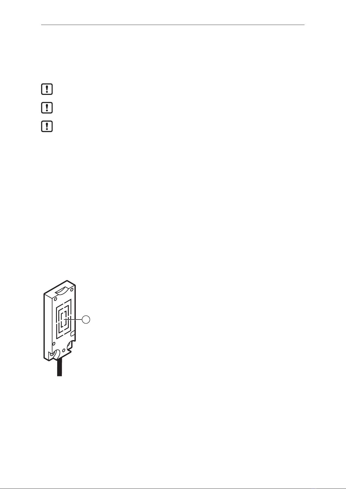
IFM ANT515 User manual

Operating instructions
RF-identification system
ANT515
ANT516
Read/write head
11456779 / 0004 / 2022
GB

ANT515 ANT516
2
Contents
1 Preliminary note ............................................................. 3
1.1 Symbols used.......................................................... 3
1.2 Warnings used ......................................................... 3
1.3 Legal and copyright information ............................................ 3
2 Safety instructions............................................................ 4
3 Intended use................................................................ 5
4 Function ................................................................... 6
4.1 ID tags ............................................................... 6
4.2 Device overview........................................................ 6
5 Installation.................................................................. 7
5.1 Notes on the unit installation............................................... 7
5.2 Avoiding interference .................................................... 7
5.3 Mechanical design ...................................................... 7
5.4 Installation of the device with the mounting adapter on tanks . . . . . . . . . . . . . . . . . . . . . . 7
5.5 Installation of the device with mounting adapter on the pipe . . . . . . . . . . . . . . . . . . . . . . . 9
5.6 Installation of the device without mounting adapter . . . . . . . . . . . . . . . . . . . . . . . . . . . . . . 10
5.7 Mounting distances...................................................... 10
5.8 Positioning of the ID tags ................................................. 10
6 Electrical connection.......................................................... 12
6.1 Wiring................................................................ 12
7 Operating and display elements................................................. 13
8 Maintenance, repair and disposal................................................ 14
9 Approvals/standards.......................................................... 15
Glossary................................................................... 16

ANT515 ANT516
3
1 Preliminary note
You will find instructions, technical data, approvals and further information using the QR code on the
unit / packaging or at www.ifm.com.
1.1 Symbols used
Requirement
Instructions
Reaction, result
[...] Designation of keys, buttons or indications
Cross-reference
Important note
Non-compliance may result in malfunction or interference.
Information
Supplementary note
1.2 Warnings used
ATTENTION
Warning of damage to property
1.3 Legal and copyright information
© All rights reserved by ifm electronic gmbh. No part of these instructions may be reproduced and
used without the consent of ifm electronic gmbh.
All product names, pictures, companies or other brands used on our pages are the property of the
respective rights owners.

ANT515 ANT516
4
2 Safety instructions
General
• The unit described is a subcomponent for integration into a system.
– The system architect is responsible for the safety of the system.
– The system architect undertakes to perform a risk assessment and to create documentation in
accordance with legal and normative requirements to be provided to the operator and user of
the system. This documentation must contain all necessary information and safety instructions
for the operator, the user and, if applicable, for any service personnel authorised by the
architect of the system.
• Read this document before setting up the product and keep it during the entire service life.
• The product must be suitable for the corresponding applications and environmental conditions
without any restrictions.
• Only use the product for its intended purpose (Ò → Intended use).
• If the operating instructions or the technical data are not adhered to, personal injury and/or damage
to property may occur.
• The manufacturer assumes no liability or warranty for any consequences caused by tampering with
the product or incorrect use by the operator.
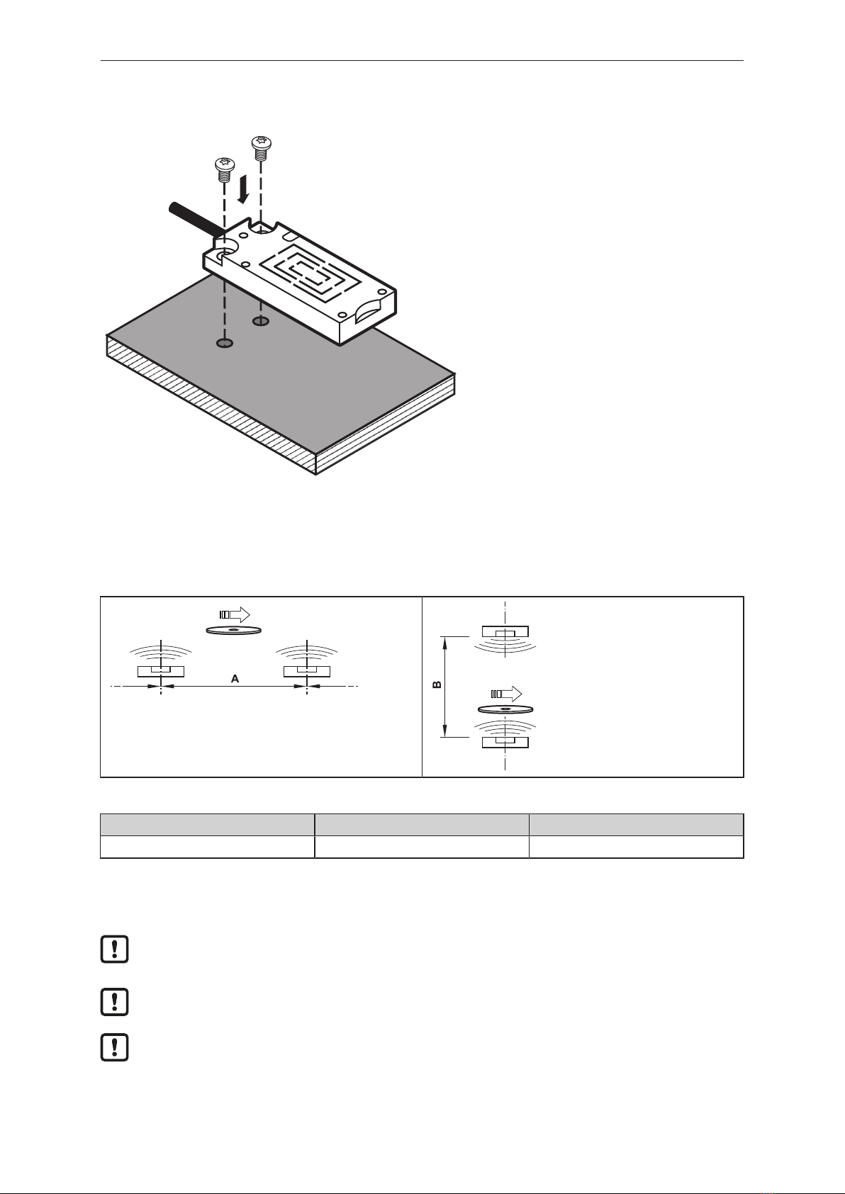
• Installation, electrical connection, set-up, operation and maintenance of the product must be
carried out by qualified personnel authorised by the machine operator.
• Protect units and cables against damage.
Radio equipment
In general, radio equipment must not be used in the vicinity of petrol stations, fuel depots, chemical
plants or blasting operations.
uDo not transport and store any flammable gases, liquids or explosive substances near the unit.
Interference of electronic and medical devices
Operation can affect the function of electronic devices that are not correctly shielded.
uDisconnect the device in the vicinity of medical equipment.
uContact the manufacturer of the corresponding device in case of any interference.

ANT515 ANT516
6
4 Function
4.1 ID tags
The ID tags are passively operated without a battery. The energy required for operation is provided by
the read/write head.
The energy is provided via an inductive coupling. The integrated antenna coil in the read/write head
generates a magnetic field which partly penetrates the antenna coil of the ID tag. A voltage is
generated by induction that supplies the data carrier with energy.
The device supports ID tags according to ISO 15693.
4.2 Device overview
Article number: ANT515 / ANT516
Function: read/write head
Type designation: DTRHF KQRWIDUS03
Type: rectangular

ANT515 ANT516
7
5 Installation
5.1 Notes on the unit installation
When mounting several RFID units adhere to the minimum distances between the systems.
Flush mounting of a read/write head in metal reduces the read/write distance.
Device performance can be affected if positioned in the immediate vicinity of powerful HF
emission sources such as welding transformers or converters.
5.2 Avoiding interference
The device generates a modulated electrical field with a frequency of 13.56 MHz.
Avoid interference with data communication:
uDo not operate any devices in the vicinity that use the same frequency band.
wSuch devices are for example frequency converters and switched-mode power supplies.
If there are other devices in the same frequency band in the vicinity:
uThe mounting distances between the devices should be as large as possible.
uUse the devices in alternating operation.
uSwitch the HF field of the device on/off.
5.3 Mechanical design
1
1 Sensing face
5.4 Installation of the device with the mounting adapter on tanks
The mounting adapter for tanks is available as accessory: article number E12153.

ANT515 ANT516
8
1
2
Fig.1: Insert the device in the mounting adapter
1 Upper edge of the device 2 Lower edge of the device
uInsert the upper edge of the device (1) into the mounting adapter.
uInsert the lower edge of the device (2) into the mounting adapter.
The device can be inserted into the mounting adapter E12153 in both directions.
3
Fig.2: Attach the device to the mounting adapter
3 Screws
uUse the enclosed screws (3) to attach the device to the mounting adapter.

ANT515 ANT516
9
4
Fig.3: Attach the mounting adapter to the tank
4 Screws
uAttach the mounting adapter to a tank with suitable screws (4).
5.5 Installation of the device with mounting adapter on the pipe
The mounting adapter for pipes is available as accessory: article number E12163.
Fig.4: Installation with cable ties
uPull the cable ties through the openings of the mounting adapter.
uSecure the device with cable ties to a pipe.
Metal cable ties may influence the degree of efficiency of the sensor.
uUse plastic cable ties.

ANT515 ANT516
10
5.6 Installation of the device without mounting adapter
Fig.5: Install the device using screws
uAttach the device at the mounting location with suitable screws or glue.
5.7 Mounting distances
Operating mode Distance side (A) Distance front (B)
For reading and writing ≥ 160 mm ≥ 170 mm
5.8 Positioning of the ID tags
The sensing face marks the centre of the integrated antenna coil of the read/write head.
uAlign the sensing face of the read/write head and the ID tag in the same way.
For installation in or on metal use the ID tags provided for this purpose.
Position the ID tag in the area of the sensing face. When doing so, the angle of aperture and the
operating distance must be adhered to (→ Data sheet of the device).

ANT515 ANT516
11
D
Fig.6: Position the ID tag
uAlign the ID tag on the central axis of the antenna of the device.
wThe distance “D” is indicated in the data sheet.
The indications in the table apply to static read/write operations.

ANT515 ANT516
12
6 Electrical connection
The device must be connected by a qualified electrician.
Device of protection class III (PC III).
The electrical supply must only be made via PELV/SELV circuits.
uDisconnect power before connecting the device.
6.1 Wiring
uConnect the unit to a DTE10x evaluation unit via the M12 connector.
wVoltage is supplied via the evaluation unit.
Pin assignment Wiring
4
1
3
L+
1
3
4
L
DATA
Information on available sockets see: www.ifm.com.
Cables with the following characteristics are suitable for the connection:
Length Ohmic resistance (feed + return line) Effective cable capacity
< 20 m max. 3 Ω max. 3 nF

ANT515 ANT516
13
7 Operating and display elements
1 2
Fig.7: Operating and display elements
1 LED 2 Sensing face
LED State Description
green On Operating voltage OK
Off Operating voltage missing
Flashing slowly deactivated
yellow On (permanently) ID tag detected
On (pulse) ID tag read/written successfully
Flashing quickly Error when reading/writing on ID tag
Off • no ID tag in the field
• faulty ID tag in the field
• invalid ID tag in the field
green and yellow Flashing alternately Error in communication or device fault

ANT515 ANT516
14
8 Maintenance, repair and disposal
The unit is maintenance-free.
uContact ifm in case of malfunction.
uDo not open the housing as the unit does not contain any components which can be maintained by
the user. The unit must only be repaired by the manufacturer.
uClean the device using a dry cloth.
uDispose of the unit in accordance with the national environmental regulations.

ANT515 ANT516
16
Glossary
ID tag
An ID tag is used to identify objects. A read/
write device is used to read the ID tag via a
high-frequency radio signal. An ID tag
consists of an antenna, an analogue circuit
for receiving and transmitting (transceiver),
a digital circuit and a non-volatile memory.
This manual suits for next models
1
Table of contents
Other IFM RFID System manuals