Innova 3360 User manual

OWNER’S
MANUAL
3360
Thermal
Imager

QUICK USE GUIDE
GENERAL OPERATION STEPS ..................................................
INSTRUMENT POWER SUPPLY .................................................
INFRARED THERMAL IMAGING DISPLAY INFORMATION .......
ABSTRACT .......................................................................................................
CHARACTERISTIC ...........................................................................................
TECHNICAL INDICATORS ...............................................................................
SKETCH MAP ...................................................................................................
POWER SUPPLY ..............................................................................................
BUTTON OPERATION ......................................................................................
SETTINGS MENU
EMISSIVITY ADJUSTMENT ........................................................
UNIT SETTINGS ..........................................................................
LIMIT VALUE SETTING ...............................................................
COLOR TABLE OPTIONS ...........................................................
DATE AND TIME ..........................................................................
STORAGE ....................................................................................
ALARM .........................................................................................
BACKLIGHT ADJUSTMENT ........................................................
FUSION DISTANCE .....................................................................
LANGUAGE SELECTION ............................................................
INFORMATION .............................................................................
PRECAUTIONS .................................................................................................
SYSTEM UPGRADE AND AFTER SALES SUPPORT ....................................
ADDENDUM
EMISSIVITY ..................................................................................
EMISSIVITY TABLE ......................................................................
BATTERY INSTALLATION .................................................................................
1
1
2
3
3
4
5
6
7
8
9
10
10
11
11
13
15
15
16
17
17
18
18
19
20
Table of Contents
i

Quick Use Guide
GENERAL OPERATION STEPS
1. Long Press “Back/Power ” button for 3 seconds -
Instrument will switched on, the screen will display the boot screen,
and the thermal image will appear after the boot screen appeared.
2. Put the Thermal Imager points to target area or object and check
thermal image -
The relative temperature is shown from hot to cold through the color
table (corresponding to light to dark). The infrared temperature reading
(shown above the thermal image) indicates the temperature of the
target measuring point aimed at the cross cursor on the display screen.
3. Press the “UP ” button or press the “DOWN ” button
The fusion ratio of infrared and visible light can be adjusted.
4. Press the trigger button -
The display screen stops, showing the thermal image at the moment,
and the thermal image will be surrounded by white boxes .
5. After image capture, press “OK” button to save the captured thermal image -
The thermal image is stored in the internal storage of the instrument in
the form of pictures. The thermal image can be viewed through USB.
Press the return button to continue to scan the target area or object.
6. In the process of scanning the area or object at which the lens is
aligned, press “OK” button can enter menu options -
In menu options can set various parameters and view meter
information (see 8. Setting menu). Press “Back/Power ” button
can exit the menu.
INSTRUMENT POWER SUPPLY
The instrument power supply mode is AAA (No.7 ) alkaline batteries, use
three alkaline dry cells to make the instrument work.
Long press “Back/Power ” button 3s starting up, power o is also long
press “Back/Power ” button 3s.
1

1. Emissivity
2. Time
3. Battery Capacity
4. Center Temperature
5. Target Temperature
6. Color Bar
7. Minimum Temperature Position
8. Maximum Temperature Position
9. Maximum Temperature
10. Minimum Temperature
Quick Use Guide
Infrared Thermal Imaging Display Information
2

ABSTRACT
3
ABSTRACT
CHARACTERISTICS
2.0 inch 240 x 320 TFT LCD display.
32 x 32 pixel infrared sensor.
Image capture frequency 7Hz.
Thermal sensitive(NETD) -<254mK.
Cold hot spot automatic capture.
Visible camera and image storage(BMP).
Internal memory stores images and can store more than 100pcs.
Set the time and date and adjust the emissivity.
3 x ”AAA” alkaline battery power supply.
USB interface connect the computer to check the photo.
IP54 waterproof level
The device is a professional thermometer, the instrument adopts 32 x 32
pixels of thermal imaging sensors and a 30w pixels of photoelectric sensors,
in addition with a 2.0” TFT LCD color display.
Combined with infrared thermal imaging and temperature sensor and optical
sensor images of auxiliary, able to provide a rapid, simple and accurate for
most of the surface temperature of detection, the location of the specic and
clear understanding of the object surface temperature.
At the same time, the instrument can also store the thermal image images
at a certain time, and the image information can be viewed through the
computer connection, so as to facilitate the analysis of thermal images in the
later period.

4
TECHNICAL INDICATORS
TEMPERATURE
Temperature Range ..............................
Temperature Measurement Accuracy .
Screen Shot Rate Correction ..............
IMAGE PERFORMANCE
Image Capture Frequency ...................
Sensor Type ..........................................
Thermal Sensitive(netd) ......................
Infrared Band ........................................
Visible Camera .....................................
Field of View .........................................
The Focal Length .................................
IMAGE DISPLAY MODE
Color Table ...........................................
Level and Span ....................................
FUSION INFORMATION
Visible and Infrared Fusion Distance .
View Options ........................................
Hot Spot and Cold Spot Tracking .......
IMAGE CAPTURE AND STORAGE
Tacking Pictures ...................................
Storage Medium ...................................
Document Format .................................
Memory Viewing ...................................
Operating Temperature ........................
Storage Temperature ............................
Relative Humidity .................................
Display Screen ......................................
Waterproong Grade ............................
-20 to 600°C (-4 to 1112°F)
±2% ±2°C (±3.6°F) as tested at 25°C (77°F)
Yes
7Hz
Non-refrigerating heat release point
254mk
8 to 14µm
307200 Pixel
33° x 33°
Fixed focal length
Iron Red, Color Red, Grayscale (White
Heat), Grayscale (Black Heat)
Automatic
0.5m, 1.0m, 2.0m
50% Step
Yes
Yes
Internal ash storage can store over 100
pieces
BMP
View or delete stored photos from the menu
0 to 50°C (32 to 122°F)
-20 to 60°C (-4 to 140°F)
10% to 90% non-dewfall
2.0 inch, 240 x 320 TFT LCD
IP54

1
5
1. LCD Display Screen
2. Up Button
3. Conrm/Menu Button
4. Back/Power Button
5. Down Button
6. Battery Cover
7. Lanyard Hole
8. Visible Light
9. Infrared Sensor
10. Trigger Button (HOLD Key)
11. Micro USB Interface
SKETCH MAP

6
Long press “Back/Power ” button 3 second to open or turn o
the Thermal Image device.
This device is powered by 3pcs “AAA” batteries, when the battery
is full, the battery status icon in the upper right corner of the display
shows full white full size “ ”.
As the battery charge decreases, the white portion of the battery
icon also drops.
When the battery symbol is displayed in red, the battery level is
low, you should replace the new one immediately.
If the battery with insucient battery is not replaced in time, the
measured temperature reading may be inaccurate.
APO-Automatic Shutdown: The Thermal Image device will
automatically shut down after a period of inactivity, and the meter
default APO time is 10 minutes.
POWER SUPPLY

7
BUTTON OPERATION
Except HOLD button, the Thermal Image device has four control buttons on the button of
the display screen.
Tip: Use the thumb button to control the trigger with the index
nger
1. Back/Power Button “ ”
Long press: Repeatedly open turn o the meter power.
Short press: Exit menu option or drop storage photos.
2. Conrm/Menu Button “OK”
Short press: Enter menu options, determine change parameters,
conrm to save photos or delete images (Preview photos).
3. Up and Down Buttons “ ”
Short press: Scroll through the options in the setup menu and scroll
through the saved photos in image review mode. In measurement
mode, scroll up and down the navigation buttons to see a blend of
visible and infrared thermal images in dierent proportions.
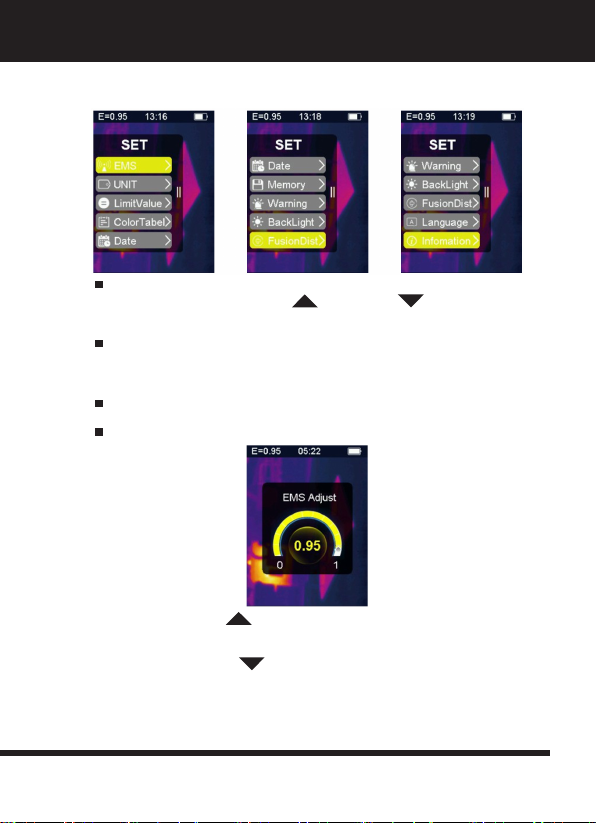
Long press: In the settings menu option, long press the up and down
navigation buttons can add or subtract values continuously, for
example, when adjusting the emissivity, press and hold for a long time,
the emissivity value will increase continuously, and the same goes
down
4. HOLD Button
Pressing the Trigger key (Also called the HOLD key) the displays still
motion, holding the infrared thermal image or visible light image at this
moment.
Press the Trigger key again, the display will show the area or object
that the infrared scans at this time.
This cycle repeats.
5. Taking Pictures and Saving Pictures
This meter can hold at least 100 photos in internal memory.
The instrument is aimed at the area or target object to be measured
Press the Trigger key (HOLD Button), the screen image is still.
Press “Conrm/Menu OK” Button, to save the current photo, a
progress bar below the picture shows the progress of the picture saved
Press the “Back/Power ” Button, to cancel the save photo,
return to continue scanning the target object.
1.
2.
3.
4.

SETTINGS MENU
In scan measurement mode, press the “Conrm/Menu OK” Button, to enter the settings
menu overview, as shown below:
The yellow highlight bar in the menu option corresponds to the
selected option, press “Up ” and “Down ” Button scroll
highlight bar
Press “Conrm/Menu OK” Button enter the corresponding options,
each option is described in detail as follows:
EMISSIVITY ADJUSTMENT
For the denition of emissivity, please refer to Appendix 11 for details.
After entering the emissivity option, the interface is as shown below:
Press the “Up ” Button, the emissivity will increase; long press
will increase continuously.
Press the “Down ” Button, the emissivity will decrease;
Long press will continuously decrease.
Press the “Conrm/Menu OK” Button, Conrm to change current
emissivity and exit emissivity adjustment interface.
1.
2.
3.
4.
8

Press the “Back/Power ” Button, to exit the emissivity setting
interface, the emissivity value is not modied.
UNIT SETTINGS
Unit settings can be set to dierent unit displays.
After entering the unit options, the interface is as shown below:
Press the “Up ” Button, the yellow highlight bar moves to another
option.
Press the “Down ” Button, the yellow highlight bar moves to
another option.
Press the “Conrm/Menu OK” Button, to conrm to change current
temperature unit and exit unit setting interface.
Press “Back/Power ” Button, to exit the unit setting interface
and the unit will not be modied.
1.
2.
3.
4.
5.
SETTINGS MENU
Unit Settings
9

LIMIT VALUE SETTING
After entering the Limit Value option, the interface is as shown below:
Press the “Up ” Button, the yellow highlight bar moves to another
option.
Press the “Down ” Button, and the yellow highlight bar
moves to another option.
Press the “Conrm/Menu OK” Button, conrm the change of the
current Limit Value to turn on the light and exit the Limit Value setting
interface.
Press the “Back/Power ” Button, to exit the Limit Value switch
setting interface, the Limit Value switch is not modied.
COLOR TABLE OPTIONS
After entering the color table option, the interface is as shown below:
Press the “Up ” Button, and the yellow highlight bar moves up.
Press the “Down ” Button, and the yellow highlight bar
moves down.
Press the “Conrm/Menu OK” Button, to conrm changing the current
color bar and exit the color table setting screen.
SETTINGS MENU
Limit Value Setting
1.
2.
3.
4.
1.
2.
3.
10

SETTINGS MENU
Date and Time
Press “Back/Power ” Button, to exit the color table setting inter
face, the color table display will not be modied.
DATE AND TIME
After entering the date and time option, the interface is as shown
below:
The yellow highlight bar corresponds to that option, and
correspondingly changes the value in that option.
Press the “Up ” Button, and the corresponding number will
increase.
Press the “Down ” Button, and the corresponding number will
decrease.
Press the “Conrm/Menu OK” Button, the yellow highlight bar will jump
to dierent items in sequence.
Press the “Back/Power ” Button, to exit the date and time setting
interface and save the current set time and date.
STORAGE
After entering the storage options, the interface is as shown below:
11
1.
2.
3.
4.
5.
4.

Highlight the selected picture, as shown below:
The white box shows the picture stored in the internal memory of the
meter.
Press the “Up ” Button, the blue highlight bar will move up.
Press the “Down ” Button, and the blue highlight bar moves down.
Press the “Back/Power ” Button, to exit the storage interface.
Press the “Conrm/Menu OK” Button, to enter the picture preview
interface, displaying the current blue.
Delete the picture, as shown in the following gure:
Press the “Up ” Button, to display the previous picture.
Press the “Down ” Button, to display the next picture.
Press the “Back/Power ” Button, to return to the storage
interface.
Press the “Conrm/Menu OK” Button, to pop up the conrmation
window to delete the picture.
12
SETTINGS MENU
Storage
1.
2.
3.
4.
5.
1.
2.
3.
4.

Press the “Conrm/Menu OK” Button, select “Yes” to conrm the
deletion of the picture, and that the window is closed automatically and
the next saved picture is displayed.
Press the “Back/Power ” Button, and select “No” to cancel
deleting the picture, Conrm that the window is automatically closed.
ALARM
After entering the alarm options, the interface is as shown below:
Press the “Up ” Button, the yellow highlight bar moves to another
option.
Press the “Down ” Button, and the yellow highlight bar moves to
another option.
Press the “Back/Power ” Button, to exit the alarm setting interface.
Press the “Conrm/Menu OK” Button, to enter the corresponding high
Alarm/Low alarm interface according to the highlight selection bar.
If you select the high alarm option, enter the high alarm interface as
shown below:
13
1.
2.
3.
4.
5.
6.
SETTINGS MENU
Alarm

Press the “Up ” Button, the high temperature alarm threshold will
increase; long press can increase continuously
Press the “Down ” Button, the high temperature alarm threshold
will decrease; long press can reduce continuously.
Press the “Conrm/Menu OK” Button, to open or close the start button
“ ”.
Open this button to indicate that if the measured object is higher than
the set maximum temperature threshold, the instrument will have an
alarm sound; if it is closed, no alarm will sound.
Press the “Back/Power ” Button, to exit the high alarm interface
and return to the alarm options interface.
If you select the low alarm option, enter the low alarm interface as
shown below:
Press the “Up ” Button, to increase the threshold for low
temperature alarms; press and hold to increase continuously.
Press the “Down ” Button, and the threshold for low temperature
alarms will decrease; long presses will reduce them continuously.
Press the “Conrm/Menu OK” Button, to open or close the start button
“ ”.
If this button is turned on, it indicates that if the measured object is
higher than the set minimum temperature threshold, the instrument will
have an alarm sound; if it is closed, no alarm will sound.
14
1.
2.
3.
4.
5.
1.
2.
3.
4.
SETTINGS MENU
Alarm

BACKLIGHT ADJUSTMENT
After entering the backlight adjustment options, the interface is as
shown below:
Press the “Up ” Button, to increase the brightness of the display
backlight; long press can increase continuously.
Press the “Down ” Button, the display backlight brightness will
decrease; long press can continuously reduce.
Press the “Conrm/Menu OK” Button, to conrm changing the current
backlight brightness and exit the backlight adjustment screen.
Press the “Back/Power ” Button, to not change the backlight
brightness and exit the backlight adjustment interface.
FUSION DISTANCE
By using aligned visible images and infrared images, image fusion
makes it easier to understand infrared images.
The product captures a visual image with each infrared image to
accurately display the target area and share it more eectively with
others.
After entering the fused distance option, the interface is as shown
below:
SETTINGS MENU
Backlight Adjustment
1.
2.
3.
4.
15

Press the “Up ” Button, and the yellow highlight bar moves up.
Press the “Down ” Button, and the yellow highlight bar
moves down.
Press the “Conrm/Menu OK” Button, to conrm changing the fusion
distance corresponding to the current color bar and exit the Fusion
distance setting interface.
Press the “Back/Power ” Button, to exit the fused distance
setting interface and the fusion distance will not be modied.
LANGUAGE SELECTION
This setting can set the meter to display in dierent national languages.
Enter the language selection option, and the interface is as shown in
the gure below:
Press the “Up ” Button, the yellow highlight bar moves to another
option.
Press the “Down ” Button, and the yellow highlight bar
moves to another option.
Press the “Conrm/Menu OK” Button, and conrm to change the
language of the current highlight bar and exit the language setting
interface.
Press the “Back/Power ” Button, to exit the language selection
setting interface, the language selection is not modied.
SETTINGS MENU
Language Selection
1.
2.
3.
4.
1.
2.
3.
4.
16

INFORMATION
This option shows the factory information, version number, etc. of the
instrument.
Enter the information options, the interface is as shown below:
Model Model of Instrument
SN Serial Number of Instrument
Version Version Number
Release Date Factory Date
Press the “Back/Power ” Button, to exit the information display
interface.
PRECAUTIONS
When using this product, ensure that the temperature is close to room
temperature.
Micro USB on the device can be connected to a computer via a USB
cable, the computer can view the photos which is saved in the meter.
For instrument temperature calibration, the instrument has been factory
calibrated before the shipment. If you need to calibrate, please contact
your local after-sales dealer.
Pay attention to the cleanliness of the surface of the instrument. Wipe
the case with a damp cloth if necessary.
Use a high-quality lens wipe to remove dust or stains from the meter’s
lens and display window.
Do not use abrasives or solvents to clean the case, lens, or display
window.
SETTINGS MENU
Information
17

SYSTEM UPGRADE AND AFTER SALES SUPPORT
Concerned about the company’s dynamic information, the rst time you
can understand the latest upgrade information about rmware.
If there is rmware’s update information, contact your local after-sales
dealer to upgrade the rmware.
ADDENDUM
EMISSIVITY
The emissivity indicates the energy radiation characteristics of the
material.
The emissivity of most organic materials and painted or oxidized sur
faces is approximately 0.95, which is the default setting of the
thermometer.
All objects radiate infrared energy, the amount of energy radiation is
based on the actual surface temperature of the object and the surface
emissivity.
The product perceives the infrared energy at the surface of the object
and uses this data to calculate the estimated temperature value.
Many common objects and materials (such as painted metal, wood,
water, skin, fabrics, etc.) can eectively emit energy, so it is easy to
obtain relatively accurate measurements, for surfaces that emit energy
easily (High emissivity), the emissivity is more than 90% (0.90).
This simplied approach does not apply to glossy surfaces or painted
metals because their emissivity is less than 60% (0.60), these
materials are not easy to emit energy and are classied as low
emissivity materials, in order to measure materials with lower
emissivity more accurately, emissivity corrections are required.
Adjusting the emission value usually allows the product to more
accurately calculate the actual temperature estimate.
Notice: It is dicult to determine the actual temperature of the surface with an emissivity
below 0.60 accurately and consistently, even if the emissivity and the reection back-
ground are adjusted correctly, the lower the emissivity, the greater the possible error in the
product’s calculation of temperature measurement results.
18
Table of contents
Popular Laboratory Equipment manuals by other brands

INTELLICYT
INTELLICYT iQue Screener PLUS Hardware manual

Malmet
Malmet ES915 Operation, maintenance and installation manual

Labconco
Labconco Purifier Logic+ 30132 Technical Manual and Specifications

JENCONS
JENCONS Powerpette Pro Operator instructions

Thermo Electron
Thermo Electron HAAKE Phoenix II P1 instruction manual

Panasonic
Panasonic Aicure ANUJ5014 user manual