Copyright Innovative Technology Ltd 2008 GA794-2
1 INTRODUCTION
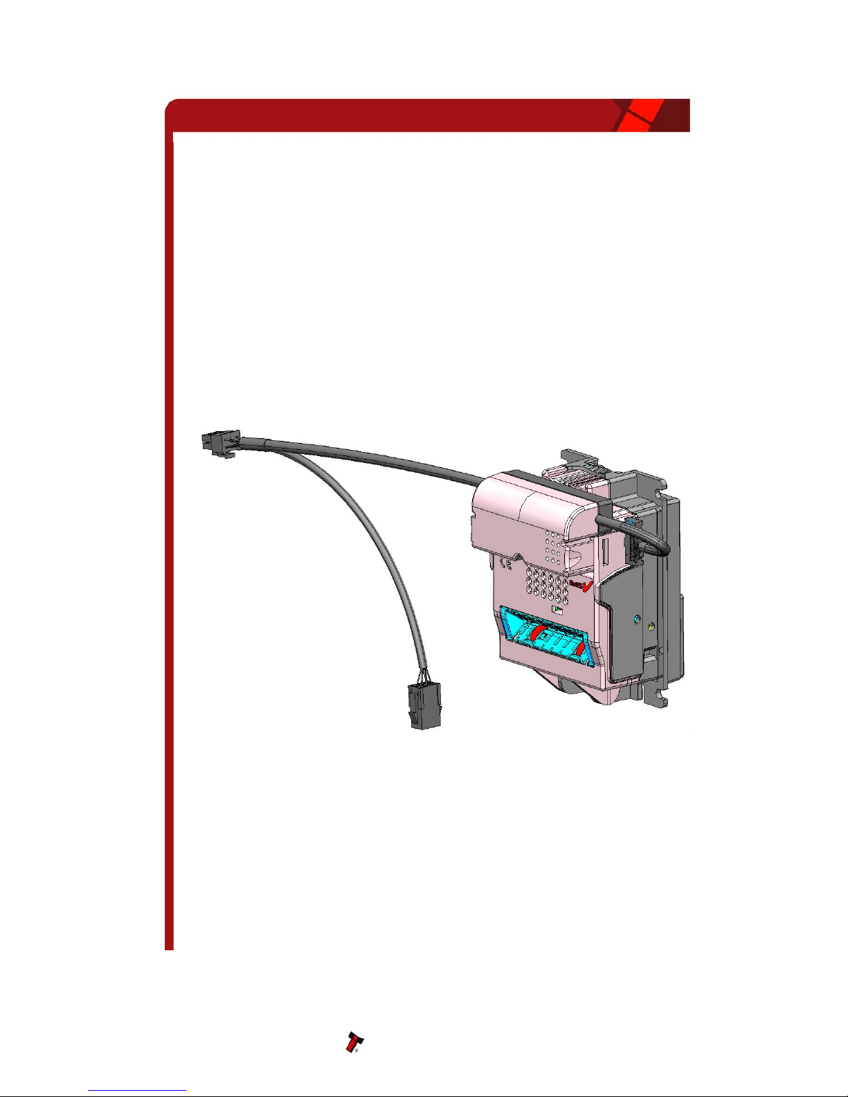
BV20 VALIDATOR - THE NEXT GENERATION OF ITL BANK NOTE VALIDATORS
This manual describes the operation of the BV20 Bank Note Validator as fitted with
Firmware Version 4.00 or greater.
This document is intended for those who will maintain the BV20 equipment.
To have full information about the configuration of this equipment, please refer, at our
website, to the operations manual (GA716).
Although information is included which will allow a degree of fault diagnosis and repair, it is
recommended that for all but simple mechanical repairs, the unit must be returned to an
approved service centre for repair.
CAUTIONS
· This product must be fitted with a 2 A (ampere) fuse before use.
· The BV20 validator is pin for pin compatible with NV7/8/9/10, but not pin for pin
compatible with the NV2/3/4/4x or 5 series products.
· Due to different note cycle times there may be timing differences from the NV products.
· Never exceed the recommended environmental and electrical limits.
· Do not attempt to lubricate the mechanisms as this may affect the note transport.
· Do not polish the lens as this may alter the optical characteristics.
· If the BV20 validator is disassembled the unit must be re-calibrated and re-initialised,
following re-assembly (See Chapter 6).
WARNING
· Only suitably trained personnel should carry out any work on this equipment in accordance
with all current local, national and international health and safety regulations.
We recommend that you study this manual as there are many new features permitting
new uses and more secure applications.
If you do not understand any part of this manual please contact the factory, contact details
are below, for assistance. In this way we may continue to improve our product.
The BV20 Validator has been designed to minimise any performance variation over time.
Much of this is achieved by careful Hardware and Software design.
Innovative Technology Ltd has a policy of continual product improvement. As a result the
products supplied may vary from the specification described here.
MAIN HEADQUARTERS
Innovative Technology Ltd
Derker Street – Oldham – England - OL1 4EQ
Tel: +44 161 626 9999 Fax: +44 161 620 2090
Web site: www.innovative-technology.co.uk
BV20 Operations Manual 3