Inoteska ITX 495 01 Operator's manual

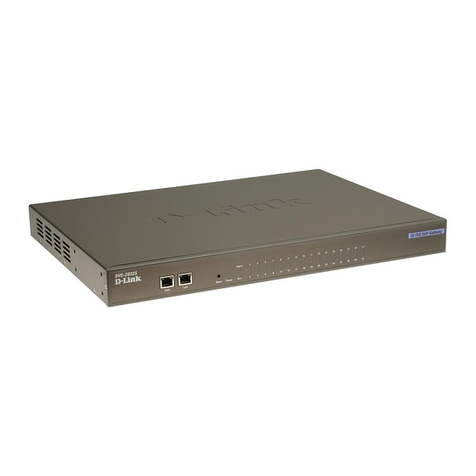
VOICE&DATA ROUTER
.
SYSTEMS FOR VOICE AND DATA COMMUNICATION
VOICE&DATA ROUTER
ITX 495 01
PRODUCT DOCUMENTATION

VOICE&DATA ROUTER
2
SYSTEMS FOR VOICE AND DATA COMMUNICATION
CONTENTS
PRODUCT OVERVIEW................................................................................................................................3
PRODUCT FEATURES ...............................................................................................................................3
VARIANTS..................................................................................................................................................5
APPLICATIONS..........................................................................................................................................6
TECHNICALSPECIFICATION.................................................................................................................10
OPERATING INSTRUCTIONS..................................................................................................................13
MANAGEMENT..........................................................................................................................................18
WEBMANAGER.......................................................................................................................................19
Users Menu............................................................................................................................................. 22
Trunks Menu........................................................................................................................................... 29
Traffic Menu...........................................................................................................................................45
Globals Menu..........................................................................................................................................59
System Menu........................................................................................................................................... 88
Diagnostics Menu.................................................................................................................................. 104
Specials Menu....................................................................................................................................... 113
UNIMAN............................................................................................................................................... 114
Connection to the device........................................................................................................................ 114
Setting of password ............................................................................................................................... 116
Configuration files editor ...................................................................................................................... 117
Diagnostics........................................................................................................................................... 119
Listing Messages................................................................................................................................... 120
Identification......................................................................................................................................... 122
TERMS OF SALE...................................................................................................................................... 123

VOICE&DATA ROUTER
3
SYSTEMS FOR VOICE AND DATA COMMUNICATION
PRODUCT OVERVIEW
The device is a multifunction VoIP gateway with application in SIP Trunking, PBX IP Trunking
and PSTN access for local IP telephony solutions. There are many usage applications
available. It is a perfect solution to decrease costs of all your calls.
PRODUCT FEATURES
OS LINUX, SD card, Asterisk SW
2 x ETHERNET 10/100 BT or 1 x 10/100 BT and 1 x 10/100 FX*
* WAN ETHERNET fiber optic interface (SC DUPLEX) can be single mode or multi mode; for single mode device
can use only 1 optical fiber; Auto MDIX option –for both Ethernet interfaces
4 x E1/T1 120/75 Ohm PRI DSS1/QSIG or R2 MFC ports software configurable
Optional interfaces:
oBRI (8/16 x BRI Uk0 or 4 x BRI S0)
oGSM (12 x GSM 2G)
oAnalogue (32 x FXS, 16 x FXO, 6 x E&M)
Console port RS232 (RJ45)
USB 1.1 host port
VoIP support: SIP, RTP, UDPTL, T.38
Codecs: G.711, G.726, G.729a/b, G.723.1
G.165 / G.168 - 2004 Echo Cancellation up to 128 ms
Silence detection / suppression and comfort noise generation (VAD/CNG)
Simultaneous calls
oVoIP –G.711: 48/64
oVoIP –G.726, G.729 a/b: 16/32
oVoIP –G.723.1, GSM: 16/24
oTDM –not limited
G.165 / G.168 - 2004 Echo Cancellation up to 128 ms
Multiple codec support
Fax over IP support, including T.38
Remote management capabilities
SIP signaling
SNMP
LCR
AOC generation
Diagnostics of all interfaces
Alarm indication
Routing to another E1/T1 if there is no more free capacity for simultaneous calls
Call Forwarding
Call Hold/Transfer
Music On Hold
Speed Dial
CLIP/CLIR
Automatic Attendant
DTMF generation and detection
Two step dial (ISDN / MFC R2 and than DTMF) - for alternative carrier
Call progress tone generation
Carrier tone generation and detection
Caller ID generation and detection (FSK)
Silence detection / suppression and comfort noise generation (VAD/CNG)

VOICE&DATA ROUTER
4
SYSTEMS FOR VOICE AND DATA COMMUNICATION
Call permissions
Calling Groups
Ring Groups
Call Pickup
Announcement playback
Remote management capabilities
HTTP, SNMP, SSH, SCP, SFTP, TFTP
Diagnostics functions

VOICE&DATA ROUTER
5
SYSTEMS FOR VOICE AND DATA COMMUNICATION
VARIANTS
1U version
ITX 495 01 Voice&Data Router –desktop with rack mount option (4 x E1/T1, optional 12 x
GSM interface, optional 32 x analogue interface, optional 4 x BRI S0, optional
16 x BRI Uk0)
19”Rack 6U version
ITX 402 41 Voice&Data Router –6U rack card (4 x E1/T1)
ITX 222 05 19’’ rack 6U
ITX 802 05 Converter DC/DC + 5V/20A
ITX 402 41 . –Voice&Data Router (rack card)
a
b
c
d
e
1 = 2km
2 = 15km
3 = 40km
4 = 80km
X = 2 optic fibers
A = Type A, 1 optic fiber
B = Type B, 1 optic fiber
1 = 1300nm
2 = 1500nm
0 = none
1 = SM (Single Mode)
2 = MM (Multi Mode)
1 = 16 channels G.729
48 channels G.711
2 = 32 channels G.729
64 channels G.711
Compression
Optic Communication
Distance
Wave Length
Optic Mode
ITX 495 01 . –Voice&Data Router
1 = 2km
2 = 15km
3 = 40km
4 = 80km
X = 2 optic fibers
A = Type A, 1 optic fiber
B = Type B, 1 optic fiber
1 = 1300nm
2 = 1500nm
0 = none
1 = SM (Single Mode)
2 = MM (Multi Mode)
0 = none
1 = RJ45
2 = BNC
1 = 230V, 48V
2 = 230V
3 = 48V
0 = none
1, 2, 3, 4, 5, 6, 7, 8, 9
a = 10, b = 11, c = 12
0 = no
1 = yes
0 = no
4 = 4 BRI S0 7 = 8 BRI S0
5 = 8 BRI Uk0 8 = 16 BRI S0
6 = 16 BRI Uk0 9 = 8 BRI Uk0, 8 BRI S0
0 = no SIP
1 = 16 channels G.729 2 = 32 channels G.729
48 channels G.711 64 channels G.711
Compression
BRI Interface
Analogue Interface
GSM Interface
Optic Communication
Distance
Wave Length
Optic Mode
E1 Interface
Power Supply
a
b
c
d
e
f
g
h
i
j

VOICE&DATA ROUTER
6
SYSTEMS FOR VOICE AND DATA COMMUNICATION
APPLICATIONS
Voice & Data Router
VoIP, TDM PBX (SW Asterisk)
TDM - VoIP Gateway
Signaling converter R2 MFC / ISDN DSS1 –SIP, Routing to another E1 if there is no more
free capacity for simultaneous calls
Concentration of max. 4xE1 (considering the limitation of max. number of simultaneous calls
depending on the codec used)
Multiple Gateway (possibility to connect several customers and divide them)
SIP PROXY Server
Voice&Data Router / VoIP, TDM PBX
TDM –VoIP Gateway

VOICE&DATA ROUTER
7
SYSTEMS FOR VOICE AND DATA COMMUNICATION
Signaling converter R2 MFC / ISDN DSS1 –SIP
Concentration of max. 4xE1/T1 (considering the limitation of max. number of simultaneous
calls depending on the codec used)

VOICE&DATA ROUTER
8
SYSTEMS FOR VOICE AND DATA COMMUNICATION
Multi Gateway (possibility to connect several customers and divide them)
E1/T1 over Ethernet (IP)
Extending

VOICE&DATA ROUTER
9
SYSTEMS FOR VOICE AND DATA COMMUNICATION
SIP PROXY Server
Local VoIP network

VOICE&DATA ROUTER
10
SYSTEMS FOR VOICE AND DATA COMMUNICATION
TECHNICAL SPECIFICATION
IP Telephony Protocols
SIP –RFC 3261
SDP –RFC 2327
RTP –RFC 1889, RFC 2833, RFC 3389
ISDN Signaling
Euro ISDN EDSS –1/ETSI PRI/ NET5
ETS 300 011 (ISDN PRI UNI)
ETS 300 012-1 ( ITU –T I.430)
ETS 300 402-2 (ITU-T Q I.921)
ETS 300 403-1/2 (ITU-T Q.931)
ETS 300 102-2 (ITU-T Q.931)
ISDN speech, audio and data (Fax Gr4, UDI 64)
CAS MFC R2 Signaling
ITU –T from Q.440 to Q.480, Q.490
ITU –T from Q.421 to Q.424
Basic Technical Requirements for Digital Switching System and PCM Transmission System
National variants, DTMF dial
GSM parameters
Quad-Band 850/900/1800/1900 MHz
GPRS multi-slot class 10/8
GPRS mobile station class B
Compliant to GSM phase 2/2+
oClass 4 (2W @850/900 MHz)
oClass 1 (1W @1800/1900 MHz)
Voice specification
Tricodec
oHalf rate (HR)
oFull rate (FR)
oEnhanced Full rate (EFR)
AMR
oHalf rate (HR)
oFull rate (FR)
Echo suppression
FAX and Modem Support
FAX Relay T.38
Supported modulations:
oV.21 Ch2
oV.27 2400 / 4800
oV.29 7200 / 9600
oV.17 7200 / 9600 / 12000 / 14400)
FAX Pass-Through –transport of fax modulations over G.711 connections
Modem Pass-Through –transport of modem modulations over G.711 connections.
Voice Processing
Supported voice codec standards
oG.711 (A-law, µ-law)
oG.723.1 and G.723.1 A
oG.726
oG.729 Annex A & B
oGSM

VOICE&DATA ROUTER
11
SYSTEMS FOR VOICE AND DATA COMMUNICATION
G.165 / G.168 –2004 Echo Canceller up to 128 ms
Robust jitter buffer
DTMF generation and detection
Call progress tone generation
Carrier tone generation
Caller ID generation and detection
Voice activity detection and comfort noise
Announcement playback
Timeslot interchange for TDM to TDM traffic processing (no compression, no delay)
Voice Channel Density
Supported Voice
Codecs
Channel Density
16/48 calls
32/64 calls
G.711
48
64
G.726
16
32
G.729 a/b
16
32
G.723.1
16
24
GSM
16
24
T.38
16
16
Voice Routing
Local switching
Low Cost Routing
Analyze called party number
Analyze calling party number
Called / calling party number modification
Call permissions
Multiple fail-over routes
Two step dialing (DTMF)
Calling groups
Ringing groups
Data Routing
Basic Routing
QoS Marking
QoS pre-router
TOS /DiffServ
Supported QoS marking
Networking
DHCP support and capabilities
Static Routing
Management
Web management –GUI
Terminal access
oLocal –control interface RS232
oRemote –LAN/WAN interface (SSH protocol)
Inoteska UniMan software
SNMP v1/2c

VOICE&DATA ROUTER
12
SYSTEMS FOR VOICE AND DATA COMMUNICATION
Power Supply
19”, 1U rack mount
85V –260 V AC or -40V to -65V DC
Frequency: 48Hz to 52 Hz
19”, 6U rack
48V DC
Max.power consumption
Max. 50W
Dimensions
19”, 1U rack mountable 44 x 282 x 485 mm (h x d x w)
Weight
Approx. 3,5kg (real weight depends on device HW configuration)

VOICE&DATA ROUTER
13
SYSTEMS FOR VOICE AND DATA COMMUNICATION
OPERATING INSTRUCTIONS
Operating Environment
Install the device in a place where:
Operating temperature: 0o C to 55o C
Storage temperature: -10o C to 65o C
Humidity: up to 80%, non-condensing
Interfaces
E1/T1 interface
Ethernet 10/100Base-T interface
RJ 45 connector
RJ 45 connector
1 –input wire to device
2 –input wire to device
3 –
4 –output wire from device
5 –output wire from device
6 –
7 –
8 –
Rx –
Rx +
Tx –
Tx +
1 –transmit from device
2 –transmit from device
3 –receive to device
4 –
5 –
6 –receive to device
7 –
8 –
Tx +
Tx –
Rx +
Rx –
Analog interfaces
Analog extension card can contain 1 up to 8 modules.
Available modules
FXS module –quad
FXO module –dual
E&M module –dual
Location of analog
modules on analog
extension card
1
A11
B11
A12
B12
A13
B13
A14
B14
2
A21
B21
A22
B22
A23
B23
A24
B24
3
A31
B31
A32
B32
A33
B33
A34
B34
4
A41
B41
A42
B42
A43
B43
A44
B44
5
A51
B51
A52
B52
A53
B53
A54
B54
6
A61
B61
A62
B62
A63
B63
A64
B64
E61
M61
E62
M62
7
A71
B71
A72
B72
A73
B73
A74
B74
E71
M71
E72
M72
8
A81
B81
A82
B82
A83
B83
A84
B84
E81
M81
E82
M82

VOICE&DATA ROUTER
14
SYSTEMS FOR VOICE AND DATA COMMUNICATION
Position No. 1 to 5: for FXS/FXO modules
Position No. 6 to 8: for FXS/FXO/ E&M modules
Connection of individual modules on J2 connector
21
40
60
1
1.module ab
2. module ab
3. module ab
4. module ab
5. module ab
6. module ab
7. module ab
8. module ab
6. module E+M
7. module E+M
8. module E+M
1
2
21
22
40
41
60
61
B83
B81
A83
A81
B84
A84
B82
A82
17
37
56
76
M81
E81
M82
E82
Analog connector

VOICE&DATA ROUTER
15
SYSTEMS FOR VOICE AND DATA COMMUNICATION
Description of J2 connector
Note: In description of connector, e.g. signal A23 means that it is a-wire from second module (first
index) of third interface on module (second index).
BRI interface
Pins are connected as TE in default configuration.
4x BRI S0 –jumper settings
Interface NT+Phantom Power NT TE .
BRIA PR22-ON PR4 1-2 PR4 2-3
PR5 1-2 PR5 2-3
PR6 1-2 PR6 2-3
PR7 1-2 PR7 2-3
BRIB PR23-ON PR8 1-2 PR8 2-3
PR9 1-2 PR9 2-3
PR10 1-2 PR10 2-3
PR11 1-2 PR11 2-3
BRIC PR24-ON PR12 1-2 PR12 2-3
PR13 1-2 PR13 2-3
PR14 1-2 PR14 2-3
PR15 1-2 PR15 2-3
NT TE
1 –
2 –
3 –Rx+ Tx+
4 –Tx+ Rx+
5 –Tx- Rx-
6 –Rx- Tx-
7 –
8 –

VOICE&DATA ROUTER
16
SYSTEMS FOR VOICE AND DATA COMMUNICATION
BRID PR25-ON PR16 1-2 PR16 2-3
PR17 1-2 PR17 2-3
PR18 1-2 PR18 2-3
PR19 1-2 PR19 2-3

VOICE&DATA ROUTER
17
SYSTEMS FOR VOICE AND DATA COMMUNICATION
GSM interface
Antenna connector: GSC connector coaxial SMT male 50R 6GHz
CONTROL RS-232 connector
CANNON -
Female for
D09F cable
RJ - 45
-
1
-
2
-
3
2
4
3
5
-
6
-
7
5
8
-
-
LED diodes
Interface
Led diode
green
Led diode
yellow
Status
E1/T1
Off
Off
Not enabled
Off
On
Not connected
Fast
CRC error or SLIP
Slow
ISDN –No DLL
Slow
AIS detected
Fast
LFA or RRA detected
On
Off
OK
Ethernet
Off
Off
Line not connected
On
(flashes during
Reception/
Transmission)
Line active
BRI S0/Uk0
Off
L1 down
On
L1 up
Off –no light, On –light, Slow –flashes slow (period 1.6sec), Fast –flashes fast (period 0.2sec, 5x/sec)
CRC Cyclic Redundancy Check error
No DLL no Data Link Layer active
AIS Alarm Indication Signal –Transmitted signal is constant with data value Log1
LFA Loss of Frame Alignment –Indicates synchronization error in 0th channel
RRA Receive Remote Alarm –Indicates remote device alarm
RJ45
Cannon D09F
+ shield

VOICE&DATA ROUTER
18
SYSTEMS FOR VOICE AND DATA COMMUNICATION
MANAGEMENT
Voice&Data Router is supplied with default configuration. Device can be configured using:
Terminal access
Inoteska Web Manager (GUI)
Inoteska UniMan
Terminal access allows direct access to the Linux console and Asterisk command line interface. User
has full low level control of the whole system. Knowledge of OS Linux, Asterisk SW and configuration
files structure is necessary.
Terminal access is available:
Locally via RS 232 control interface (baud rate 115200 bps, 8 bits, 1 stop bit, no parity)
Remotely over the Ethernet interface using SSH protocol
Login parameters for terminal access:
Login name: root
Default password: inoteska
NOTE:
Low level configuration using terminal access is not the scope of this document. Unqualified change of
system configuration can make the device non-functional. Please contact the producer in case of
difficulties!
Inoteska Web Manager (GUI) provides simple and user-friendly interface for device configuration and
supervision using web browser.
Inoteska UniMan is universal software used for communication with Inoteska equipment which
supports TCP / UDP protocol. UniMan operates under OS Windows (Win7/Vista/XP/2000). UniMan
provides text or graphical mode for device configuration.

VOICE&DATA ROUTER
19
SYSTEMS FOR VOICE AND DATA COMMUNICATION
WEB MANAGER
Web Manager is Graphic User Interface for device configuration and supervision. It was tested with
following web browsers: Opera, Google Chrome, Mozilla Firefox. MS Internet Explorer is not fully
supported and it is not recommended to use with Voice&Data Router.
Default IP address setting:
LAN: 192.168.1.100
WAN:10.1.1.100
Initial screen serves for user (system administrator) login.
Default login parameters:
Username: admin
Password*: inoteska
*Change of password can be done in Options menu.
After successful logging in Home page with device hardware configuration and identification will be
displayed.
Device configuration shows available TDM interfaces (E1/T1 trunks, BRI trunks, GSM trunks,
analogue trunks and users) and configured VoIP interfaces (SIP trunks and users). Voice&Data
Router is always supplied with 4 E1/T1 interfaces. BRI, analogue and GSM interfaces are optional and
their number depends on the hardware configuration. SIP users and SIP trunks shows the number of
interfaces configured by device administrator.
Identification provides basic information: device type (product code number), serial number, main
board identification and software version.

VOICE&DATA ROUTER
20
SYSTEMS FOR VOICE AND DATA COMMUNICATION
How to configure Voice&Data Router
Step 1
Make basic system configuration
IP setting –assign IP addresses to connect to LAN and WAN network. Configure DNS
servers. In some cases it can be necessary to configure routing table for static IP routing.
Firewall setting –configure firewall eventually NAT to keep Voice&Data Router secure from
the Internet attacks.
Date/Time setting –select time zone and actualize time in Voice&Data Router
Step 2
Configure users / trunks. This depends on usage application
Gateway –only trunk’s configuration is required usually. In some cases also users can be
needed.
PBX –both user’s and trunk’s configuration is required
Depending on the application create the users (SIP or analogue). Configure trunks to connect to
PSTN or VoIP provider (usually E1/T1 or SIP), to connect to PBX or other gateway (E1/T1, SIP or
analogue trunk), to connect to GSM network (GSM interface), etc. as per device function.
Step 3
Configure call traffic –call routing between users and trunks. Call traffic consists of
calling rules
dial plans
Calling rules define set of rules for analysis of dialed number eventually together with caller
identification number and for selection of destination of the call. Voice&Data Router in function of
gateway without users needs to specify only trunk-to-trunk calling rules. PBX device or gateway with
users requires also calling rules for user-to-user calls, user-to-trunk calls and trunk-to-user calls.
Dial plan is set of calling rules. Create dial plans from existing calling rules for users and for trunks as
needed. When all dial plans are ready go back to the user’s or trunk’s configuration to assign dial plan
for users / trunks.
Step 4
Configure all other options offered by Web Manager.
Table of contents
