Inovalley SM55PRO User manual

PROFESSIONAL WEATHER STATION
Ref.: SM55PRO
- Owner’s Manual -
Thank you for purchasing the new generation of professional weather station. Designed and engineered with the
state-of-art technology and components, this instrument will provide accurate and reliable measurement of wind
speed & direction, wind chill, daily/weekly/monthly/accumulated rainfall, barometric pressure, weather forecast,
indoor/outdoor humidity, temperature, heat index & dew point as well as radio-controlled alarm clock. Read this
manual carefully to fully explore the features and functions of the new product.
In this package you will find:
- 1 monitor (Receiver)
- 1 anemometer (Transmitter – transmit wind & outdoor Channel-1 temperature/humidity data)
- 1 rain gauge (Transmitter – transmit rainfall data)
- Mounting hardware for rain gauge (2 sets of screws & plastic screw plugs)
- Mounting hardware for anemometer (2 pieces of U-shape metal plate, 4 sets of Hex screws & nuts)
- 1 owner’s’ manual
- 3 pieces AAA batteries for monitor (included)
- 2 x 2 pieces AA for anemometer + rain gauge (included)
- 1 6.0V adapter (included)
Additional tools needed for installation:
- Small screwdriver
- Hexagonal Key
- Electric drill
- Pencil
- Level
- Mast, 1 – 1.25 inch (2.54 – 3.18 cm) in diameter (to mount the anemometer)
1/ INSTALLATION
The weather station operates at 433MHz and does not require wire installation among the component parts. To
ensure successful installation and the best performance, we recommend you follow the installation instructions in
the order they appear in this manual.
1. Battery & adapter installation for the monitor (receiver)
Main Power source: Plug in the adapter jack into the back side of the unit for basic operation and continuous
backlight.
Backup Power: Open the battery door and insert 3 pieces of AAA batteries according to the polarity indicated,
close the battery cover.
Sea level pressure setting
After battery/adapter installation, the monitor will enter sea level pressure setting mode directly and the pressure
reading will flash. Press “▲” or “▼” to set the sea level pressure value. Press “PRESSURE” to confirm the setting
and exit. This allows the unit to provide a more accurate weather forecast & pressure reading.
You can also set the sea level pressure any time after the installation is completed. For more information, see
“WEATHER FORECAST & BAROMETRIC PRESSURE” section.
Note: you may obtain the current sea level pressure from the weather web site for your locate area.
ENGLISH

2. Selecting a location for the anemometer
Select a mounting location for the anemometer that is:
- Outdoors, not blocked on top or sides, so wind can freely reach the anemometer
- Within 50 meter (164 feet) open area from the monitor. Reduce distance if obstacles is between the
anemometer & the monitor
The best location for the anemometer is usually mounted on a mast in an open area where wind is not blocked on
top or sides, or above roof level on the building where the monitor is located.
Testing the effective transmission range
Before mounting the anemometer, measure the distance between the monitor & anemometer and be sure it is
within the effective transmission range. It is recommended to perform a simple RF transmission test before
mounting.
1) Place the monitor in your selected indoor location and install adapter & batteries (see “Battery & adapter
installation for the monitor” section above)
2) Place the anemometer horizontally in your selected outdoor location. Loosen the screws on the battery
door with a small Phillips screwdriver and open the battery door. Insert 2 pieces of AA batteries according to
the polarity indicated. Close the battery door and tighten the screws.
3) Hold “CHANNEL/SEARCH” button on the monitor for 3 seconds and the wind direction, temperature &
humidity icons will flash on the display. The monitor is now searching for all remote sensors.
4) If valid wind direction, wind speed and channel-1 temperature/humidity readings are shown on the monitor
within 10 minutes, the RF transmission is successful and the anemometer & monitor are within the effective
transmission.
If above readings are not shown after 10 minutes of searching, the transmission is failed.
Shorten the distance between the anemometer & monitor. Reset the anemometer by removing all batteries
from the anemometer & wait for 10 seconds before re-installing the batteries again. Repeat step 3 & 4 until
the transmission is successful.
5) Remove all batteries from the anemometer before mounting and calibration.
NOTE: Whenever the radio-controlled icon is flashing on the display, the weather station is receiving
radio-controlled clock signal and the RF reception for remote sensors will stop temporary for around 8 minutes.
Wait until this icon stops flashing (or disappear) before searching for the remote sensors.
3. Mounting the anemometer
Important: Before mounting, be sure the monitor & anemometer are within the effective transmission range.
Note: To mount the anemometer, you need a mast (not supplied) about 1 – 1.25 inches (2.54 – 3.1 cm) in
diameter, and the hardware necessary to fasten it to the mounting location. If you previously installed such a mast
(for mounting antenna, for example), you can mount the anemometer on that mast.
1. If necessary, mount and ground a mast as directed in the instructions provided by the mast.
2. Place the supplied U-shape metal plates around the mast. Insert 4 pieces of the supplied Hex screws
through the holes of the U-shape plates and the holes on the anemometer’s mounting bracket.
(The wind vane is above the wind cup and the metal bar of the anemometer is in horizontal level)
3. Tighten the supplied Hex nut onto both ends of each screw

4. Calibrating the anemometer & installing batteries
After mounting the anemometer, follow these steps to calibrate the wind direction so that the anemometer
properly measures the wind direction and transmit to the monitor. Be sure battery has been removed from the
anemometer before the calibration.
Important: The same calibration (step 1 to 5) is needed for the first set up and every battery replacement.
1. After mounting the anemometer, loosen the screws on the battery door with a small screwdriver and open
the battery door.
2. Use the compass on the anemometer and turn the wind vane so it is pointing due north.
3. Hold the wind vane pointing due north and do not allow it to turn. Insert 2 pieces of AA batteries according
to the polarity indicated. The red LED indicator above the battery cover of the anemometer will flash few times
right after battery installation. Be sure the vane is pointing due north at the moment when red LED flashes
and the calibration is now completed. Replace the battery cover and tighten the screws.
4. If the wind vane is not pointing due north when the red LED first flashes, remove batteries and repeat step
2 & 3.
5. Hold “CHANNEL/SEARCH” buttons on the monitor to search for remote transmitter. Wind direction, wind
speed, wind chill & channel-1 temperature/humidity readings will appear within 10 minutes if the RF
transmission is successful.
5. Selecting a location for the rain gauge
Select a mounting location for the rain gauge that is:
- a flat, level surface and look for a location where the rain gauge can be placed 1 meter or more above
ground level.
- within 30 meter (100 feet) open area from the monitor. Reduce distance if obstacles is between the rain
gauge & the monitor
- in an area not blocked on the top or sides, so rain can freely reach the rain gauge (for example, not under
an overhang or too close to a building or fence)
Cautions:
- To prevent false rainfall readings caused by water splashes, do not choose a location that is not level or
that is too close to the ground, a swimming pool, lawn sprinklers, or anywhere water might accumulate or
run off
- The screen in the cylinder of the rain gauge filters most debris (such as leaves) that might fall into the rain
gauge. To avoid frequent build-up of debris in the cylinder, do not mount the rain gauge too close to the
trees or plants
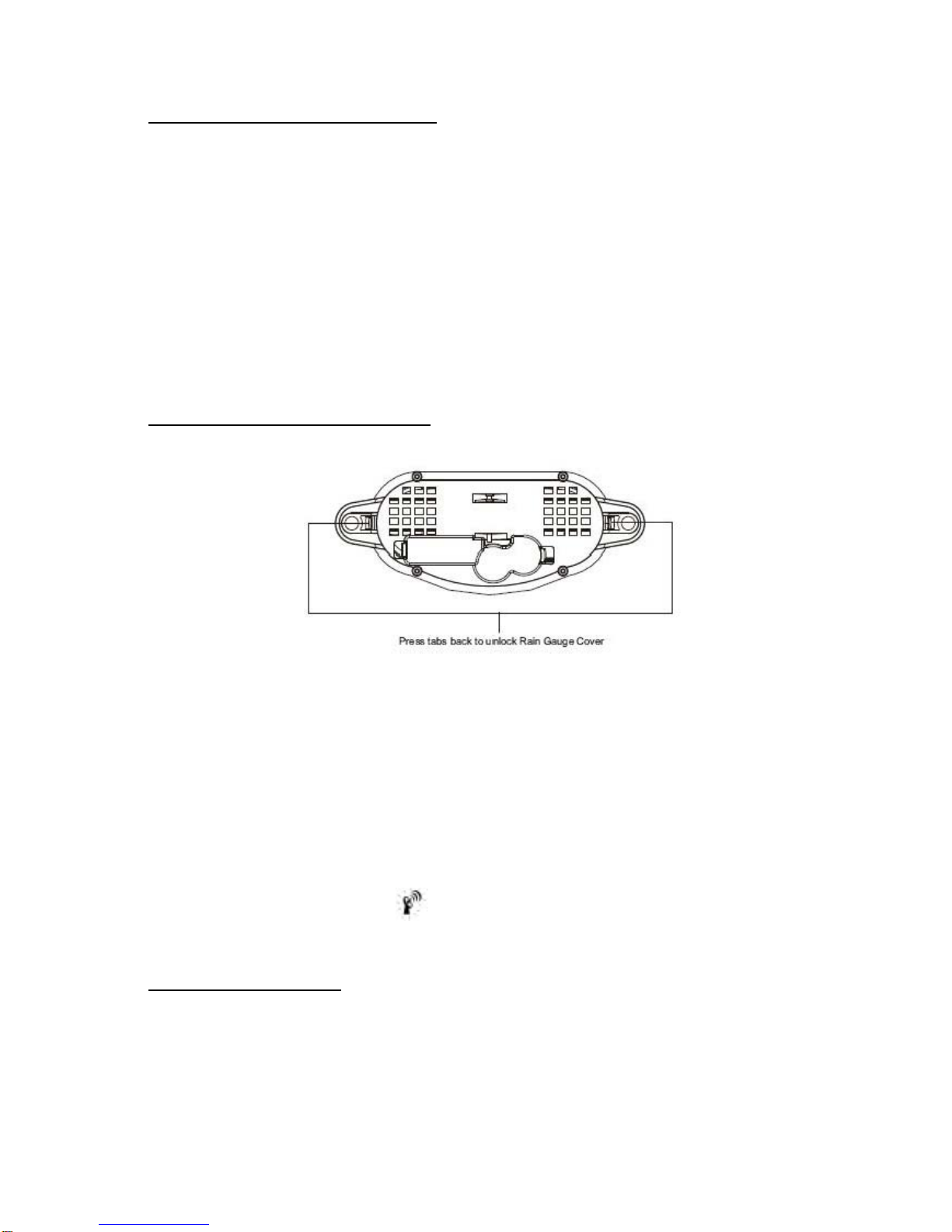
6. Battery Installation for the rain gauge
1. Press the tabs back as indicated below to unlock the rain gauge cover
2. Lift the rain gauge cover off its base. Then carefully remove the packing tape from the bucket assembly
3. Open battery cover and insert 2 pieces of AA batteries according to the polarity indicated. Close the battery
cover
4. Replace & lock the rain gauge cover on the base
5. Hold “CHANNEL/SEARCH” button on the monitor for 3 seconds and the total rainfall “- - - -“ will flash. The
monitor is now searching for all remote sensors. Total rainfall reading (in this case “0” mm) will appear within
2 minutes if the RF transmission is successful and the monitor & rain gauge are now within the effective
transmission range.
6. If total rainfall “- - - - “ stop flashing and stay on the display after 2 minutes of searching, the RF
transmission is failed. Shorten the distance between the monitor & rain gauge. Reset the rain gauge by
removing all batteries from the rain gauge and wait for 10 seconds before re-installing the batteries again.
Then repeat step 5 (& 6) until the RF communication is completed.
NOTE: Whenever the radio-controlled icon is flashing on the display, the weather station is receiving
radio-controlled clock signal and the RF reception for remote sensors will stop temporary for around 8 minutes.
Wait until this icon stops flashing (or disappear) before searching for the remote sensors.
7. Mounting the rain gauge
Before mounting the rain gauge, be sure the rain gauge & monitor are within the transmission effective range and
batteries are installed.
1. Hold the base of the rain gauge flat against the mounting surface then use a level to make sure the rain
gauge (as it rest on the mounting surface) is horizontally level.
2. Use a pencil to trace the inside of the mounting holes on the base of the rain gauge to mark the screw
locations.

3. Drill a hole in the center of each marked location and insert the supplied plastic screw plugs
4. Hold the rain gauge against the mounting surface so the holes on the base are aligned with the plugs, then
thread the supplied washer head screws into each hole and use a screwdriver to tighten them.
8. Installing additional remote thermo-hygrometer sensor(s)
Additional remote thermo-hygrometer sensors can be purchased separately (not supplied in the package).
1. Select a location for the remote thermo-hygrometer that is within the effective transmission range of 100
meters (328 feet). Shorten the distance if obstacle is between the monitor & remote sensor.
2. Use a small screwdriver to loosen the screws on the battery door of the remote sensor. Insert 2 pieces of
AAA batteries according to the polarity indicated.
3. Assign channel 2 or 3 to the remote sensor by setting the slide switch inside the battery compartment.
(Channel 1 is used by the anemometer and should not be assigned to the new remote thermo-hygrometer)
4. Press “Tx” button inside the battery compartment of the remote sensor to transmit temperature & humidity
data to the monitor. Then close the battery door and tighten the screws.
5. Hold “CHANNEL/SEARCH” button on the monitor to search for all remote sensors. The temperature &
humidity readings of your selected channel number will be displayed on the monitor if RF transmission is
successful.
2/ OPERATION
Name and Functions of Buttons:
Press Functions Hold 3 seconds
RAIN/CLEAR Read daily/monthly/weekly/total rainfall / Clear rainfall record
RAIN HISTORY Read current & past 6 days, weeks or months rainfall data
WIND Read average & gust wind speed
WIND ALARM Read high gust wind alarm and low wind
Enter high wind speed alarm & low chill alarm wind chill alarm setting
PRESSURE Toggle pressure unit hPa, inHg & mb / Sea level pressure setting
CHANNEL/ SEARCH Select indoor, Channel 1, 2, 3 or Search for all remote sensors
auto scroll
MEMORY Read maximum/minimum records Clear memory record
HEAT INDEX/ DEW POINT Read Heat Index & Dew Point
CLOCK Read time, calendar and day-of-week / Set Clock & Calendar
ALARM Read alarm time; enable/disable alarm / Alarm time setting
▲UP 1 step forward in setting / Fast advance
▼Down 1 step backward in setting / Fast backward
SNOOZE/LIGHT Trigger snooze alarm & extend backlight
WIND ALARM Enable/disable high gust wind alarm & low wind chill alarm
WIND UNIT Toggle wind speed unit between / Beaufort, mph, m/s, km/h & knot

Search for Radio-Controlled time
ZONE Toggle RC time & Zone time / Zone time setting
3/ CONNECTING WITH REMOTE SENSORS
The weather station uses 433MHz radio signals to send and receive weather data between the monitors and
remote sensors.
After battery/adapter installation, the monitor will automatically search for remote sensors.
You can also enforce a searching mode by holding “CHANNEL/SEARCH” on the monitor.
Follow the instruction in the “INSTALLATION” section to set up the sensors and wireless connection. If the
connection cannot be established, reset the remote sensor by removing the batteries from the sensor. Wait for 10
seconds and reinstall the batteries. Then hold “CHANNEL/SEARCH” on the monitor to search for the sensors. If
that continues to fail, shorten the distance between the sensor & monitor and reinstall the sensors if necessary
(Details refer “INSTALLATION” section)
NOTE: Whenever the radio-controlled icon is flashing on the display, the weather station is receiving
radio-controlled clock signal and the RF reception for remote sensors will stop temporary for around 8 minutes.
Wait until this icon stops flashing (or disappear) before searching for the remote sensors.
Anemometer (with built-in temperature & humidity sensor):
Important: Wind direction calibration is needed whenever the anemometer is reset (or during battery
replacement)
Searching mode display:
Wind direction, temperature & humidity information will flash
RF Connection completed:
Valid wind speed/direction & Ch-1 temperature/humidity readings appear
(It may take up to 10 minutes to receive all wind speed/direction & Ch-1 temperature/humidity readings during the
searching mode)
RF Connection failed:
“- - - -“ wind speed appears; no wind direction. Unable to display Ch-1 temperature & humidity
Rain Gauge:
Searching mode display:
Total rainfall information will flash
RF connection completed:
Valid total rainfall reading appears
RF connection failed:
“- - - -“ stops flashing & stays on the total rainfall display (previous daily/weekly/monthly rainfall readings remain in
record)
Additional remote thermo-hygrometer sensor:
Additional remote thermo-hygrometer sensors can be purchased separately (not supplied in the package).
Important: Select Ch-2 or 3 for additional remote thermo-hygrometer sensor since Ch-1 has been assigned to
the anemometer.
Searching mode display:
Temperature & humidity information will flash
RF Connection completed:
Valid temperature/humidity readings of your selected channel appear
RF Connection failed:
Unable to display the temperature & humidity readings of your selected channel
4/ WEATHER FORECAST & BAROMETRIC PRESSURE
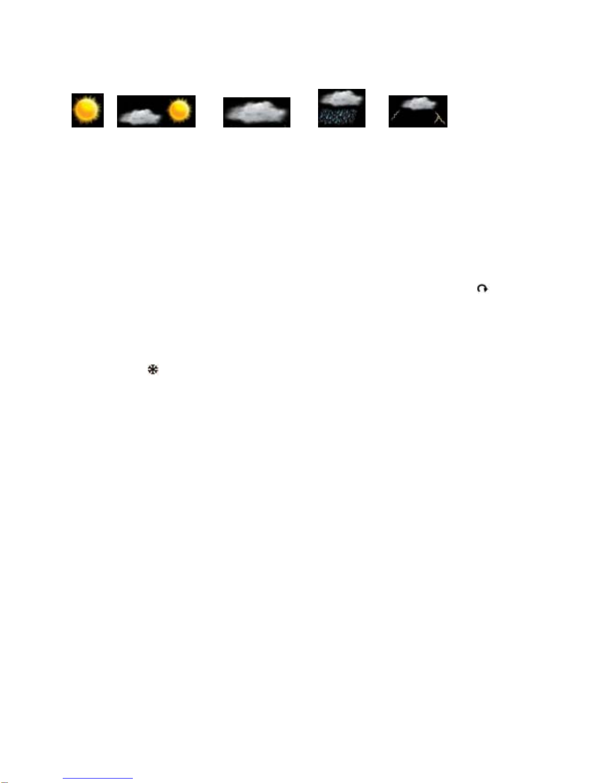
The unit predicts weather condition of the next 12 – 24 hours based on the change of atmospheric pressure.
The coverage area is around 30 – 50 km. The weather forecast is based on atmospheric pressure change and is
about 70-75% correct.
As weather conditions cannot be 100% correctly forecasted, we cannot be responsible for any loss caused by an
incorrect forecast.
SUNNY PARTLYCLOUDY CLOUDY RAINY STORMY
To obtain an accurate weather forecast & barometric pressure reading, you need to input your current local sea
level pressure. After battery/adapter installation, it will enter sea level pressure setting directly and the pressure
reading will flash. Press “▲” or “▼” to set the value and press “PRESSURE” to confirm and exit.
You can also hold “PRESSURE” button to enter sea level pressure setting in normal display mode. Press “▲” or
“▼” to set the value and press “PRESSURE” to confirm and exit.
Press PRESSURE button to select pressure unit between hPa, inHg & mb.
Note: you may obtain your current local sea level pressure information from the weather web site.
5/ IN/OUT TEMPERATURE & HUMIDITY
Temperature & humidity readings are shown on the upper right of the display.
Press “CHANNEL/SEARCH” repeatedly to select indoor, Ch1, Ch2, Ch3 or auto-channel scrolling display
modes.
Note: The outdoor temperature & humidity sensor is built inside the anemometer and is assigned to channel 1.
Additional remote thermo-hygrometer sensor(s) can be purchased separately and they should be assigned to
Ch-2 or 3 only.
6/ ICE ALERT
Ice alert indicator appears on the display next to the wind chill reading when outdoor channel-1 temperature
falls to or below 4C (or 39.2F). It provides an early alert for possible icy road condition to driver.
7/ IN/OUT HEAT INDEX
Heat Index combines the effects of heat and humidity. It is the apparent temperature of how hot the heat-humidity
combination makes it feels.
Press “Heat Index/Dew Point” button once to show the respective indoor or outdoor heat index on the display.
“HEAT INDEX” icon will appear.
Note: Heat index display range: 14C to 60C
(It shows LLL when heat index is below 14C or HHH when above 60C)
8/ IN/OUT DEW POINT
Dew point is the saturation point of the air, or the temperature to which the air has to be cooled in order to get
condensation.
Press HEAT INDEX / DEW POINT button twice to show the respective indoor or outdoor dew point reading on the
display. “DEW POINT” icon will appear.
Note: Dew point display range: 0C to 60C
(It shows LLL when dew point is below 0C and HHH when above 60C)
9/ DAILY, WEEKLY, MONTHLY & ACCUMLATED RAINFALL
The wireless rain gauge provides daily, weekly, monthly and accumulated rainfall measurements.
Press “RAIN/CLEAR” repeatedly to switch between the different modes and the corresponding “DAILY”,
“WEEKLY”, “MONTHLY” or “TOTAL” icon will appear indicating your current display mode.
In daily, weekly or monthly rainfall display, hold “RAIN/CLEAR” to clear all daily, weekly & monthly rainfall reading
to zero. In total rainfall display, hold “RAIN/CLEAR” to clear total rainfall reading.
10/ RAINFALL HISTORY
This unit has a large capacity memory that can store and display:
- Daily rainfall (up to last six days as well as current day)
- Weekly rainfall (up to last six weeks as well as current week)
- Monthly rainfall (up to last six months as well as current month)

Press “RAIN” to select daily, weekly or monthly rainfall display mode. Press “RAIN HISTORY” repeatedly to scroll
through the current & last 6 days/weeks/months data corresponding to your selected rainfall mode. On the bar
chart display, the “0” represents the current period. –1, –2, etc indicate the prior periods. The precise rainfall
reading of the selected period will be shown on the display.
Example 1:
In April, press “RAIN HISTORY” repeatedly in the monthly rainfall mode until “–3” bar chart is shown. The bar
chart and reading indicate the monthly rainfall record in January (from 1st Jan to 31st Jan)
Example 2:
On Wednesday, press “RAIN HISTORY” repeatedly in the weekly rainfall mode until “-1” bar chart is shown. The
bar chart and reading indicate the weekly rainfall recorded last week (from last Sunday to last Saturday).
Example 3:
On Friday, press “RAIN HISTORY” repeatedly in the daily rainfall mode until “–2” bar chart is shown. The bar
chart and reading indicate the daily rainfall record on this Wednesday.
11/ WIND SPEED & DIRECTION
The weather station uses the anemometer to sample the wind speed and direction. You can set the monitor to
display the wind speed in miles per hour (mph), kilometers per hour (km/h), meters per second (m/s), knots and
Beaufort. Press “WIND UNIT” on the back casing until the desired unit appears.
The monitor displays 16 wind directions (N for north, S for south, SW for south-west and so on).
Press “WIND” to select gust & average wind speed display.
Wind direction : Average wind direction over a 2-minute period
Average wind speed : Average wind speed over a 2-minute period
Gust wind speed : Maximum wind speed over a 10-minute period
Beaufort Knots Wave
height
(meter)
Wave
height
(feet)
WMO
description Effects observed on the sea
0 Under
1 - - Clam Sea is like a mirror
1 1 – 3 0.07 0.25 Light air Ripples with appearance of scales; no foam
crests
2 4 – 6 0.15 – 0.3 0.5 – 1 Light breeze Small wavelets; crests of glassy appearance,
not breaking
3 7 – 10 0.6 – 0.9 2 – 3 Gentle
breeze
Large wavelets; crests begin to break; scattered
whitecaps
4 11 –
16 1 – 1.5 3.5 – 5 Moderate
breeze
Small waves, becoming longer; numerous
whitecaps
5 17 –
21 1.8 – 2.4 6 – 8 Fresh breeze Moderate waves, taking longer form; many
whitecaps; some spray
6 22 –
27 2.9 – 4 9.5 – 13 Strong
breeze
Larger waves forming; whitecaps everywhere;
more spray
7 28 –
33 4.1 – 5.8 13.5 – 19 Near gale Sea heaps up; white foam from breaking waves
begins to be blown in streaks
8 34 –
40 5.5 – 7.6 18 – 25 Gale
Moderately high waves of greater length; edges
of crests begin to break into spindrift; foam is
blown in well-marked streaks
9 41 –
47 7 – 9.7 23 – 32 Strong Gale High waves; sea begins to roll; dense streaks of
foam; spray may begin to reduce visibility
10 48 –
55 8.8 – 12.5 29 – 41 Storm
Very high waves with overhanging crests; sea
takes white appearance as foam is blown in
very dense streaks; rolling is heavy and visibility
is reduced
11 56 –
63
11.2 –
15.8 37 – 52 Violent Exceptionally high waves; sea covered with
white foam patches; visibility further reduced

12 64 &
over
13.7 &
over 45 & over Hurricane Air filled with foam; sea completely white with
driving spray; visibility greatly reduced
(Reference table based on observations of the effects of the wind)
12/ WIND CHILL
Wind chill is the apparent temperature felt on exposed skin due to the combination of air temperature and wind
speed. The wind chill reading on the monitor is calculated based on the temperature measured from the
anemometer (channel-1) and the average wind speed.
13/ GUST WIND & WIND CHILL ALARM
High Gust Wind Alarm
You can set the monitor to sound an alarm for about 1 minute when gust wind reaches or exceeds a set limit.
Press “WIND ALARM” to silence the alarm sound. The related high alarm icons will continue to flash until the
alarm condition is no longer met.
High Gust Wind Alarm Setting:
- Press “WIND ALARM” to show high gust wind alarm display. “ALARM” icons appear in the gust wind
display area
- Hold “WIND ALARM” button to enter its setting mode and gust wind digits will flash
- Press “▲”or “▼” to set the value
- Press “WIND ALARM” to confirm setting and exit
Press “WIND AL ” repeatedly to enable or disable the gust alarm. “ ” appears when it is enabled.
Low Wind Chill Alarm
You can also set the monitor to sound an alarm for about 1 minute when the wind chill reaches or falls below the
set limit. Press “WIND ALARM” to silence the alarm sound. The related low alarm icon will continue to flash until
the alarm condition is no longer met.
Low Wind Chill Alarm Setting:
- Press “WIND ALARM” repeatedly so “ALARM” icons appear in the wind chill display area
- Hold “WIND ALARM” button to enter its setting mode and the wind chill digits will flash
- Press “▲”or “▼” to set the value
- Press “WIND ALARM” to confirm setting and exit
Press “WIND AL ” repeatedly to enable or disable the wind chill alarm. “ ” appears when it is enabled.
14/ MAXIMUM & MINIMUM RECORDS
Press “MEMORY” repeatedly to view the maximum & minimum values of temperature, humidity, heat index, dew
point, wind speed & wind chill readings. The corresponding “MAX” and “MIN” icons will appear. To clear the
memory record, hold “MEMORY” in the max/min display mode
15/ RADIO-CONTROLLED CLOCK
The unit will start synchronizing the radio-controlled clock after battery/adapter installation. The antenna icon will
flash during synchronization. If the reception of radio-controlled time is successful, antenna icon with full signal
strength will appear on screen. The radio-controlled clock will have a daily synchronization at 02:03 & 03:03
everyday. Each reception cycle is around 2.5 to 10 minutes.
Antenna icon
disappear
Searching for Radio-Controlled Clock
Signal
Reception is
successful
Reception is
fail Reception is disabled
Antenna icon without signal strength indicates the past reception is not successful (Daily synchronization is still
enabled). To enforce searching of radio-controlled time signal immediately, press repeatedly until the antenna

icon flashes. If reception continues to fail, try other locations later. Place the unit away from source of interference
such as mobile phones, appliances, TV etc.
To disable the radio-controlled time reception and stop the daily synchronization, continue pressing until the
antenna icon disappears.
16/ CLOCK & CALENDAR
Press “CLOCK” to toggle display between time, calendar and day of the week.
Clock & calendar setting:
Note: You need to set clock & calendar when your weather station cannot receive radio-controlled time signal in
your location.
- Hold “CLOCK “ button to enter clock setting mode.
- Using “▲”or “▼“ to adjust and “CLOCK” to confirm, the following values can be set in sequence:
12/24hr format > Hr > Min > Yr > D/M or M/D format > Month > Date > EXIT
17/ HOME TIME, WORLD (ZONE) TIME
Hold “ZONE” to enter world (zone) time setting mode. Press “▲“or “▼“ to enter the desired hour offset value from
–12 to +12 hours. Press “ZONE” to confirm each setting.
Press “ZONE“ button to toggle between home (radio-controlled) time and world (zone) time. “ZONE” icon appears
when world (zone) time is selected. When zone time is not used, set zone time to “0”.
18/ ALARM SETTING
Press “ALARM” button to show alarm time and the “ALARM” icon will appear. Press again to enable or disable
the alarm. Bell icon “ ” appears when alarm is enabled.
Hold “ALARM” to enter alarm time setting mode. Press “▲”or “ ▼” to enter the desired Hour/ Min values and
press “ALARM“ to confirm setting.
19/ SNOOZE & BACKLIGHT
When alarm is going off, press SNOOZE/ LIGHT to trigger snooze function and “Zz” icon will appear. To stop
alarm for one day, press “ALARM” key.
Once adapter is connected to the monitor, it will provide continuous backlight to the display
Press SNOOZE/LIGHT for an extended backlight if adapter is not connected.
20/ LOW BATTERY INDICATION
Low battery indication is available for the monitor itself and all of the remote sensors. Replace
the batteries and follow the setup procedure in this instruction manual.
Important: Wind direction calibration is required for the anemometer during battery replacement
(Details refer “Calibrating the anemometer & installing batteries” section)
21/ BATTERY DISPOSAL & PRECAUTIONS ON THE USE OF BATTERIES
- Replace only with the same or equivalent type recommended by the manufacturer.
- Discard a used battery in nature or garbage pollutes and prevents the recovery of recyclable materials.
It is therefore important to limit consumption of batteries and follow these guidelines:
focus on alkaline batteries (that last longer than the saline batteries) and when possible, rechargeable
batteries
deposit batteries and accumulators in specific containers arranged among traders.
For example, metals will be valued and polluted the environment because they contain heavy metals hazardous
to health and the environment primarily (cadmium and nickel)
- The piles must installation by respecting the polarity indicated on the apparatus and the pile.
An incorrect positioning can is to damage the apparatus, is to cause escapes on the level of the pile, is to the
extreme to cause a fire or the explosion of the pile.
- To ensure proper operation, the batteries must be in good condition. In case of abnormality in the functioning of
the device, put fresh batteries
- Never attempt to recharge non-rechargeable batteries. They could run, warm up, causing a fire or explosion.
- Replace all batteries at the same time.

Never mix zinc batteries with alkaline batteries or rechargeable batteries
- The batteries must be removed from the device
- Also, remove the batteries from your device if you do not use it for a long time, if the batteries may leak and
cause damage.
- Never try to short-circuit the battery terminals
- Never dispose of batteries in fire, they might explode
- Charging of batteries is to be performed by an adult.
- Remove batteries from the device before reloading.
- We recommend an adult to supervise children when they change the batteries so that these instructions are
complied with or to make himself the replacement of batteries.
- If a battery is swallowed, immediately consult a doctor or poison control center nearest you. Do not forget to
carry the product with you.
22/ SPECIFICATIONS
Indoor Temperature : 0 C to + 50 C (+32 F to +122 F)
Outdoor Temperature : -20 C to +60 C (-4 F to +140 F)
Heat Index : 14C to 60C
(shows LLL when heat index below 14C & HHH when above 60C)
Dew Point : 0C to 60C
(shows LLL when dew point below 0C & HHH when above 60C)
Temperature Resolution : 0.1 degree C
Indoor & Outdoor Humidity : 20% - 99% RH
Humidity Resolution : 1% RH
Channel for Temp & Humidity : maximum 3
Wind speed range : 0 – 30m/s
: 0 – 108 km/h
: 0 – 67 mph
: 0 – 58.3 knot
: 0 - 11 Beaufort
Rain Gauge reading : 0 – 9999 mm
Transmission (Anemometer) : up to 50M (164 feet) in open area
Transmission (Rain Gauge) : up to 30M (98 feet) in open area (1m above ground level)
Clock : DCF77 Radio-Controlled, Quartz back-up
Power : 3 pieces AAA batteries & 1 piece 6.0V adapter for monitor (included)
: 2 pieces AA for anemometer (included)
: 2 pieces AA for rain gauge (included)
IMPORTANT NOTE:
Warning! The weather station and the outside sensor contain sensitive electronic components. Radio waves
transmitted e.g. from mobile telephones talkies -walkies, radios, WiFi, remote controls or microwaves may
influence the transmission distance of the weather station and the outside sensor and lead to a shorter reception
range. It is therefore important to keep as great distance as possible between the devices of the weather station
and the outside sensor and the devices which send out radio waves. We do not guarantee the maximum
specified transmission range between the weather station and the outside sensors due to the radio frequency
interference in the environment.
Other Inovalley Weather Station manuals


