Inovonics EN1941XS User manual

7.24.19 357-06288-01 Rev A © Inovonics, 2019 - www.inovonics.com
EN1941XS One-Way Serial RF Module
Installation and Operation Manual
1 Overview
EchoStream one-way serial RF modules are designed to be easily
interfaced with your electronic remote application controller (RAC). Your
RAC contains application specific functionality and uses the RF module to
send application-specific data over the wireless network. The RF module
communicates with your application controller via a wireless connection,
and your RAC via a serial connection, allowing the assimilation of any user-
specific application into an EchoStream system. Once integrated with an
existing product, an RF module provides you with complete EchoStream
functionality.
The EN1941XS, equipped with the UART logic-level serial connection, is
primarily intended for use as a daughter board, interfacing directly with your
RAC.
Figure 1 One-way system components
1.1 Maximum Number of Repeaters for a UL 2560
Installation
To achieve the 99.99% alarm message reliability required for UL 2560
compliance, system installations must operate within the following limits for
end device and repeater counts.
1.2 Inovonics Wireless Contact Information
If you have any problems with this procedure, contact Inovonics Wireless
technical services:
• E-mail: [email protected]
• Phone: (800) 782-2709; (303) 939-9336
2 One-Way Serial RF Module Components
The EN1941XS one-way serial RF module is designed to physically
interface with your product. Serial data sent to the E*1941XS from your
remote application controller is formatted by the EN1941XS, and the data is
then transmitted as an RF message to the network coordinator.
Figure 2 One-way serial RF module components
Secondary alarm Driving pin high triggers a secondary serial alarm status
message.
Primary alarm Driving pin high triggers a primary serial alarm status
message.
Tamper input Driving pin high triggers a serial tamper status message
from the RF module to the RAC. Does not trigger an RF tamper message.
Reset input Connects a reset input, to reset the one-way serial data RF
module.
Power Connect power cabling to an external power supply of 2.6 to 5.5
volts.
Ground Connects to ground.
Mounting hole Used to mount the one-way serial data RF module to the
user-specific product. The mounting hole should only be used with a nylon
standoff, never metal.
Data output Outputs messages to the RAC.
Data input Receives messages from the RAC.
3 One-Way Serial RF Module Dimensions
Figure 3 One-way serial RF module dimensions
End Devices Maximum
Repeaters
150 397
250 386
350 375
500 360
1000 313
2000 238
3000 184
For product and installation videos visit us at
www.inovonics.com/videos or use the QR code
below.
AMounting hole BData output CData input
DSecondary alarm EPower FGround
GPrimary alarm HLED contacts ITamper input
JReset input
B
C
G
DI
J
E
F
A
H
1.3”
Pitch:
2.54mm.
.385” to
Center of
First Pin
.090” to
Center
of First
Pin .335” to
Center
of Hole
.515” to
Center of
Hole
.156”
Diameter
.5”
2.525”

7.24.19 357-06288F-01 Rev A © Inovonics, 2019 - www.inovonics.com 2
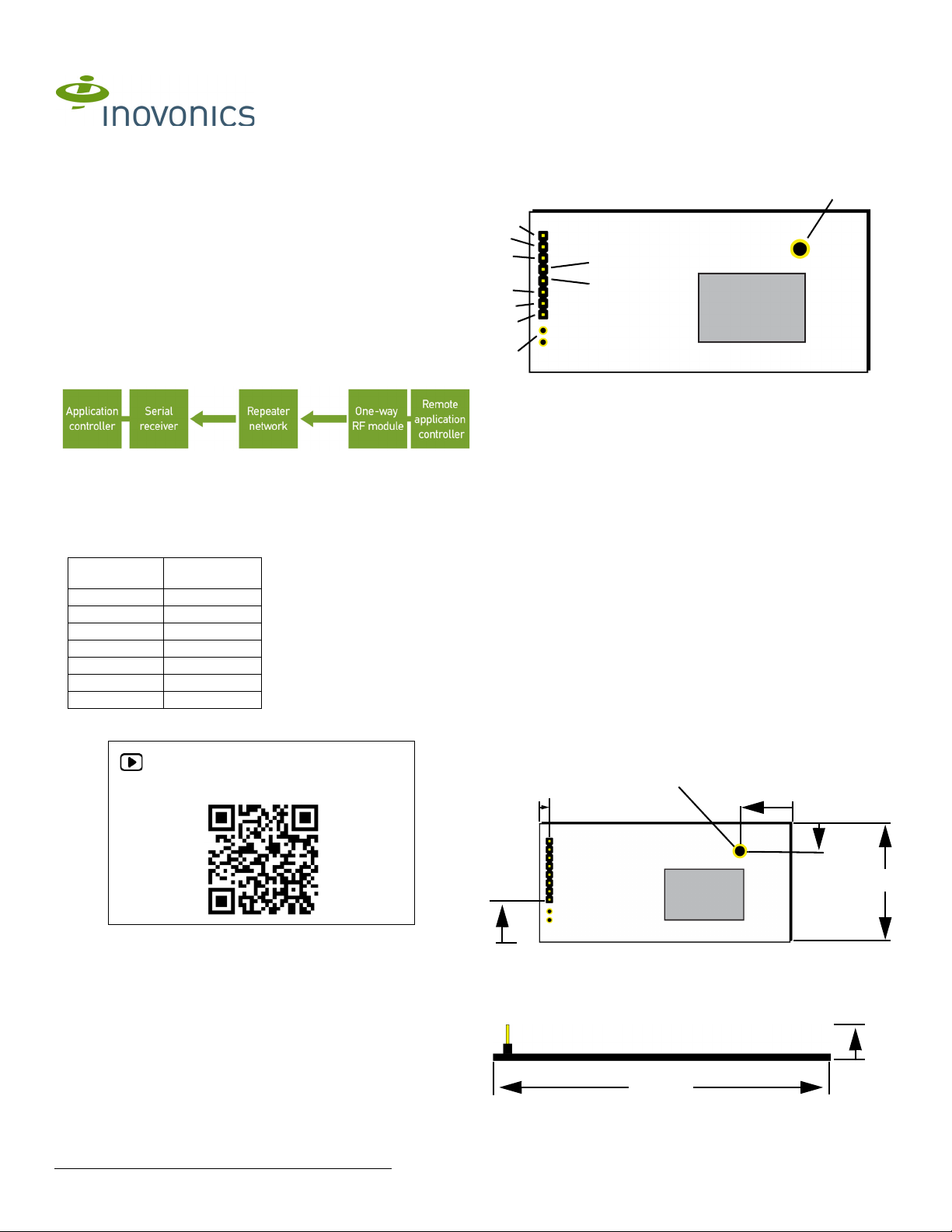
4 One-Way Serial RF Module Connections and
Output Jumpers
5 Installation Notes
• The RF module must only be connected at the eight pin header or
eight pin plated thru-holes.
• All cables and wires must be routed away from the component side of
the RF module.
• The integrated antenna must not be tampered with; no connection to
an alternate antenna is provided.
• The application module must not include an integrated secondary
colocated radio module.
• The one-way serial data RF module antenna should be placed so that
it is facing away, or otherwise isolated from, your device’s ground
plane.
• Components that are sensitive to RF transmission, such as high gain
circuits, should be isolated from the antenna to prevent interference.
• One-way serial RF modules should not be mounted on metal surfaces
or inside metal enclosures. They should also not be mounted where
sheet metal ductwork, wire mesh screens, etc. might block
transmissions.
6 One-Way Serial RF Module Requirements
6.1 Timing Requirements
All data is sent at a default rate of 9600 baud, no parity, 8 data bits and one
stop bit. The data is transmitted least significant bit first.
6.2 Power Requirements
The EN1941XS has an on-board voltage regulator. Connect power cabling
to an external power supply (Vcc) of 2.6 to 5.5 volts. Voltage must be
sustained at 2.6 volts or above and supply 100 milliamps during the
transmit cycle.
Assuming check-in messages every 3 minutes and infrequent alarm
messages (one per day, on average), the average current draw is 32 uA.
Peak current draw while transmitting is less than 100 mA. One alarm/
restore cycle with the maximum payload size results in approximately a
23mA increase in the average current.
6.3 Low Battery Condition
The EN1941XS measures power supply voltage every three and a half
hours, and, when the voltage measures 2.6 volts, a serial message is sent
indicating a low battery condition.
6.4 Temperature Range
-20°C to +60°C, non-condensing
6.5 RF Network Compatibility
EchoStream Commercial Mesh Network
6.6 Payload size
50 bytes maximum
6.7 Input Requirements
Caution: Input levels must not exceed 3.3 V.
Open When an active source (open collector or dry contact) is used to
drive the alarm or tamper input, the voltage should be between 0.75xVcc
and Vcc. A passive input should have an impedance of greater than 5.1k
ohm between the input and ground.
Closed When an active source is used, the voltage should be less than
0.25xVcc. A passive input should have an impedance of less than 240
ohm.
6.8 Serial I/O - UART logic-levels
Input levels must not exceed 3.3 V. Output levels are limited to 3.3 V,
maximum.
Data in pins Vih (minimum high level input voltage): 0.75xVcc
Data in pins Vil (maximum low level input voltage): 0.25xVcc
Data out pins Voh (minimum high level output voltage): Vcc - 0.25 at Ioh: -
1.5mA
Data out pins Voh (minimum high level output voltage): Vcc - 0.6 V at Ioh: -
6mA
Data out pins Vol (maximum low level output voltage): 0.25 V at Iol: 1.5mA
Data out pins Vol (maximum low level output voltage): 0.6 V at Iol: 6 mA
6.9 UL2560 Requirements
• The EN1941XS one-way serial RF module is a UL2560 unlisted
component.
• The compatible receiver for UL 2560 installations is the EN6040-T
network coordinator. Refer to the EN6040-T Network Coordinator
Installation Instructions.
• For UL 2560 installations, the RF module must have a minimum
check-in time of 60 minutes.
• The compatible repeater for UL 2560 installations is the EN5040-20T.
• In a UL 2560 installation, the EN1941XS one-way serial RF module
may be used with completed emergency call systems for assisted
living and independent living facilities
• For UL 2560 certified system installations, the following Inovonics
EchoStream devices are approved for installation within maximum
system configuration limits defined in section 1.1 of this document:
- EN6040-T network coordinator.
- EN5040-20T high power repeater.
- End devices (transmitters) with a minimum 60-minute check-in
interval, as follows:
Fundamental devices which are subject to UL2560 certification
(pendant transmitters and OEM products using the Inovonics RF
module)
Supplemental devices which are not subject to UL2560 system
certification but which may be used within a UL2560 certified
system (e.g. universal transmitters and activity sensors)
• Users that have achieved certification and will install UL 2560 certified
systems are responsible for labeling all fundamental devices with the
UL 2560 system certification mark.
7 Specifications
Output power: 25mW.
Firmware revision: 90651, v1.1.
8 Compliance Requirements
8.1 FCC Requirements for the EN1941XS
The EN1941XS one-way serial data RF module has received a Limited
Modular Grant, requiring Inovonics to retain control of the final installation
to ensure compliance to FCC/IC regulations. The integrator is responsible
to test the final installation to verify compliance to FCC/IC regulation for
unintentional emissions.
Prior to marketing the product, the integrator must complete and submit to
Inovonics a compliance review form and documentation, and, if requested,
a functional product sample for approval. If this is not possible, the
integrator must perform the testing themselves and submit proof to
Inovonics of compliance to Part 15 of the FCC Rules and Industry Canada
RSS-210.
At the end of this guide is an Inovonics compliance review form to be filled
out by the integrator.
The integrator is also responsible for properly labeling the product
containing the one-way serial data RF module. Labels must be placed on
Connection Output Jumper N/C
Primary Alarm
Open Alarm
Ground Alarm Clear
Secondary
Alarm
Open Alarm
Ground Alarm Clear
Tamper
Open Tamper
Ground Tamper Clear
Reset Open for normal operation; connect to the ground and
release for a board reset.

7.24.19 357-06288F-01 Rev A © Inovonics, 2019 - www.inovonics.com 3
the outside of the product, and must include a statement indicating that the
product contains the module, along with the FCC and IC number.
Example 1 “Contains One-Way Serial RF Module
FCC ID: HCQ3B6OT9OEM; IC ID: 2309A-OT9OEM (EN1941XS-IC)”
Example 2 “Contains FCC ID: HCQ3B6OT9OEM; IC ID: 2309A-OT9OEM
(EN1941XS-IC)”
9 Television and Radio Interference
This equipment has been tested and found to comply with the limits for a
Class B digital device, pursuant to Part 15 of the FCC Rules. These limits
are designed to provide reasonable protection against harmful interference
in a residential installation. This equipment generates, uses and can
radiate radio frequency energy and, if not installed and used in accordance
with the instructions, may cause harmful interference to radio
communications. However, there is no guarantee that interference will not
occur in a particular installation. If this equipment does cause harmful
interference to radio or television reception, which can be determined by
turning the equipment off and on, the user is encouraged to try to correct
the interference by one or more of the following measures:
• Reorient or relocate the receiving antenna.
• Increase the separation between the equipment and receiver.
• Connect the equipment into an outlet on a circuit different from that to
which the receiver is connected.
• Consult the dealer or an experienced radio/TV technician for help.
10 FCC Part 15 and Innovation, Science and
Economic Development Canada (ISED)
Compliance
This device complies with part 15 of the FCC Rules, and ISED license-
exempt RSS standard(s). Operation is subject to the following two
conditions: (1) this device may not cause interference, and (2) this device
must accept any interference that may cause undesired operation of the
device.
Le présent appareil est conforme aux CNR Innovation, Sciences et
Développement économique Canada applicables aux appareils radio
exempts de licence. L'exploitation est autorisée aux deux conditions
suivantes: (1) l'appareil ne doit pas produire de brouillage, et (2) l'utilisateur
de l'appareil doit accepter tout brouillage radioélectrique subi, même si le
brouillage est susceptible d'en compromettre le fonctionnement.
11 Radiation Exposure Limits
11.1 FCC
This equipment complies with FCC radiation exposure limits set forth for an
uncontrolled environment. In order to avoid the possibility of exceeding the
FCC radio frequency exposure limits, human proximity to the antenna shall
not be less than 20 cm during normal operation and must not be co-located
or operating in conjunction with any other antenna or transmitter.
11.2 ISED
This equipment complies with ISED RSS-102 radiation exposure limits set
forth for an uncontrolled environment. This transmitter must be installed to
provide a separation distance of at least 20 cm from all persons and must
not be co-located or operating in conjunction with any other antenna or
transmitter.
Cet équipement est conforme avec ISED RSS-102 des limites d'exposition
aux rayonnements définies pour un environnement non contrôlé. Cet
émetteur doit être installé à au moins 20 cm de toute personne et ne doit
pas être colocalisé ou fonctionner en association avec une autre antenne
ou émetteur.

7.24.19 357-06288-01 Rev A © Inovonics, 2019 - www.inovonics.com 4
Inovonics One-Way Serial RF Module Compliance
Review Form
Please provide the following information for review of final installation to
ensure compliance with FCC/IC regulations:
Required materials from integrator
The following must also be attached for review with this form:
• A description of the final installation, with attached photographs, as
necessary
•The unintentional radiator test report indicating compliance
Integrator information
Inovonics contact information
Inovonics
ATTN: Product Management
397 South Taylor Ave.
Louisville, CO 80027
Phone: 303.939.9336
Toll-Free: 800.782.2709
Fax: 303.939.8977
First name: Last name:
Phone number: Email address:
Address:
Declaration of conformity to Inovonics’ installation instructions:
Submitted materials:
Authorized signature: Submission date:

7.24.19 357-06288-01 Rev A © Inovonics, 2019 - www.inovonics.com 5
Required materials from Inovonics
• The record of product sample review and test, as necessary
Inovonics approval
First name: Last name:
Phone number: Email address:
Approval status (pass, fail, samples required, compliance testing required, compliance test report
required):
Approval comments:
Submitted materials:
Returned materials:
Authorized signature: Approval date:
Table of contents
Other Inovonics Control Unit manuals