manuals.online logo
Brands
  1. Home
  2. •
  3. Brands
  4. •
  5. Inovonics
  6. •
  7. Security Sensor
  8. •
  9. Inovonics EN1751 User manual

Inovonics EN1751 User manual

10.25.16 06809A © Inovonics, 2016 - www.inovonics.com
EN1751 Water Detector
Installation Instructions
1 Overview
The Inovonics EN1751 water detector is used with the Honeywell® FP280
probe, sold separately, to detect water from leaking hot water heaters or
similar appliances, alarming when 1/4” or more of non-distilled water is
present. The EN1751 water detector sends a primary alarm (alarm0) to
indicate the presence of water, and a secondary alarm (alarm1) to indicate
other fault conditions described in section 4, “Operation” on page 2.
1.1 Inovonics Contact Information
If you have any problems with this procedure, contact Inovonics Wireless
technical services:
• E-mail: [email protected]
• Phone: (800) 782-2709
1.2 EN1751 Components
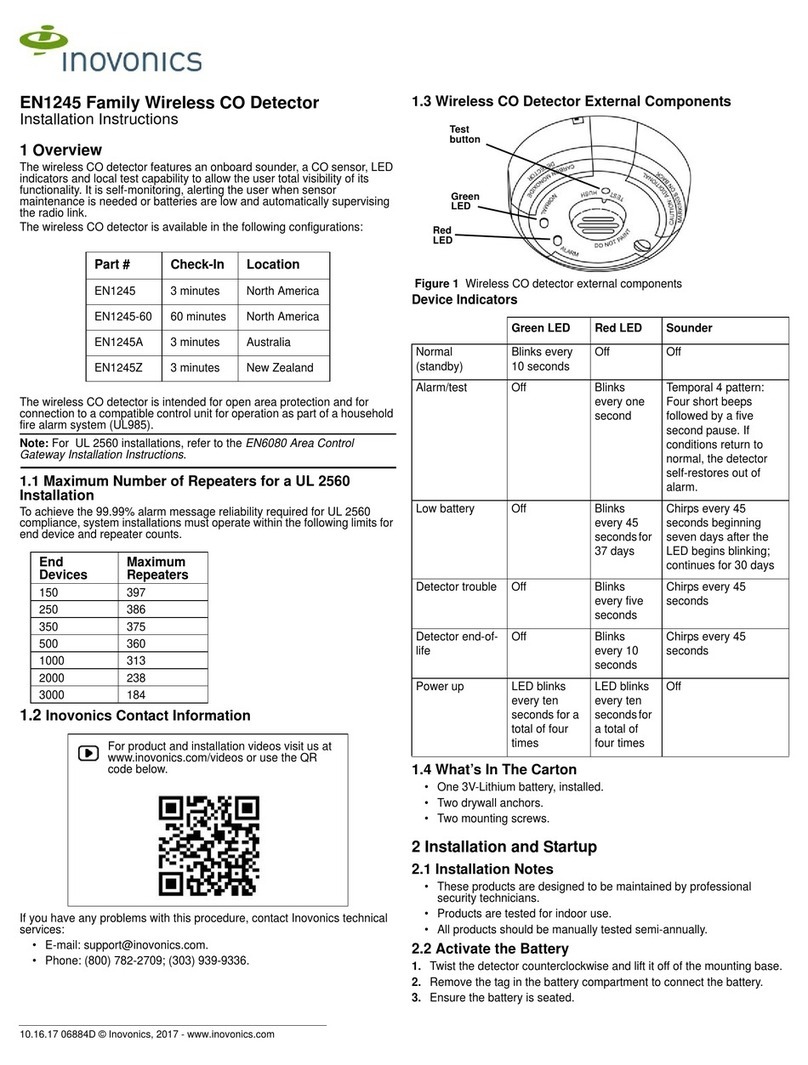
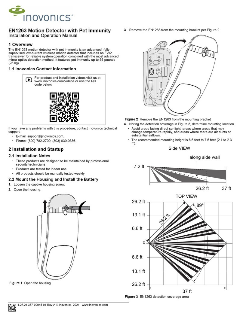
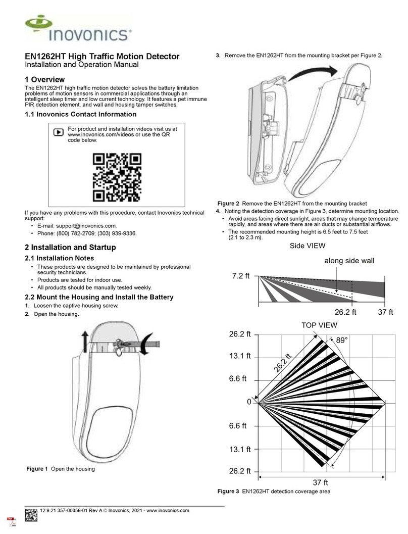
Figure 1 EN1751 components
1.3 What’s In The Carton
The following are included with individual units only; they are not included
in bulk sales.
• Three wall mount screws.
• Three wall mount anchors.
• Two selection jumpers.
• One 3.0V lithium battery.
2 Installation and Startup
2.1 Installation Notes
• These products are designed to be installed and maintained by
professional security technicians.
• Products are intended for indoor use.
• Manually test all products weekly.
2.2 Install the Battery
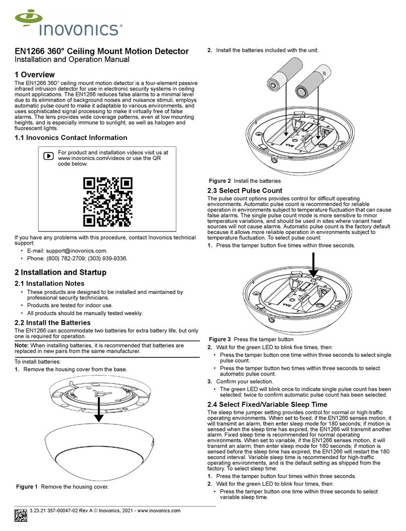
1. Pry the top lip of the mounting bracket up, and lift the bracket off of the
transmitter.
2. Use your thumb to depress the housing release tab on the bottom of the
transmitter; separate the housing.
3. Install the new battery.
4. Press the reset button to initialize the transmitter.
2.3 Mount the Honeywell FP280 Probe
The Inovonics EN1751 water detector is used with the Honeywell FP280
probe. To mount the Honeywell FP280 probe:
5. Trim the FP280 probe wiring to the desired length.
6. Route the FP280 probe wiring through either the rectangular back
wiring cutouts on the back of the housing and bracket, or through the
rounded top wiring cutout at the top of the housing.
Note: If you want to use the cutout at the top of the housing, you will need
to trim the bracket.
7. Use a small screwdriver to attach the FP280 probe wiring leads to the
power terminal block.
8. Use double-sided tape to attach the FP280 probe to the bottom of the
water heater drip pan. If no drip pan is present, secure the FP280 on
the floor where water is likely to collect.
9. Press the reset button to complete configuration.
2.4 Select the Frequency Band
EchoStream products are able to use a range of radio frequencies, and
must be configured for your geographic area. This product ships with a
default frequency range of 902-928 MHz for use in North America. If you
are using the product in North America, skip to section 2.5, “Register the
EN1751 Water Detector”; if you are using the product in Australia or New
Zealand, you will need to configure the transmitter.
10. Place a selection jumper on the appropriate frequency band selection
pins.
• Place the jumper on the right two pins, marked NZ, to set the
frequency range to 921-928 MHz for New Zealand.
• Place the jumper on the left two pins, marked AU, to set the frequency
range to 915-928 MHz for Australia.
11. Press the reset button to complete configuration.
Caution: When pressing the reset button, make sure you don’t also touch
the frequency band selection pins. Touching the frequency band selection
pins while pressing the reset button can inadvertently set the single input
universal transmitter to the wrong frequency band.
2.5 Register the EN1751 Water Detector
The EN1751 water detector must be registered with the system in order to
be monitored and supervised. Refer to the receiver installation instructions
for details on registering a transmitter.
12. When prompted by the receiver to reset transmitter, press the reset
button.
13. Replace the cover.
2.6 Mount the EN1751 Water Detector
14. Attach the mounting bracket to the desired location, using the included
screws or double-sided tape.
Note: There are two mounting holes for standard installation. An optional
third mounting hole is located under the battery. Use the third mounting
hole to secure the housing to the bracket.
15. Hook the bottom of the EN1751 water detector into the bracket’s bottom
catch, and press the EN1751 into the bracket so that the bracket’s top
lip snaps into place.
For product and installation videos visit us at
www.inovonics.com/videos or use the QR
code below.
AFrequency band selection pins BTop wiring cutout
CReset button DProbe terminal block
EBack wiring cutout
AC
D
E
B
Draft
10.25.16 06809A © Inovonics, 2016 - www.inovonics.com 2
16. Use staples or tape to secure the wiring between the EN1751 water
detector and the FP280 probe.
17. Test the EN1751 and FP280 per section 3, “Testing the EN1751 Water
Detector”.
3 Testing the EN1751 Water Detector
The EN1751 water detector should be tested weekly and after registration
to ensure operation.
To test the EN1751 water detector:
1. Inspect to ensure both the EN1751 and FP280 are securely mounted
and the wiring is still secured.
2. Submerge the FP280 probe in 1/4” of non-distilled water and ensure an
appropriate response.
When testing has completed, you will need to reset the EN1751. To reset
the EN1751:
1. Remove the EN1751 water detector from the mounting bracket.
2. Use your thumb to depress the housing release tab on the bottom of the
transmitter; separate the housing.
3. Press the reset button.
4. Replace the housing and return the transmitter to the mounting bracket.
4 Operation
The primary alarm, alarm0, is sent when the EN1751 detects water; the
other two alarms, alarm1 and alarm2, and the tamper message are sent in
the following cases:
Note: If an alarm0 message is sent and no water is present, inspect the
wiring at the probe terminal block to ensure that there is no short.
Note: The EN1751 water detector cannot reliably detect frozen water.
5 Specifications
Dimensions: EN1751: 3.5” x 1.7” x 0.9”; FP280: 1.5” x 1.0” x 0.375”.
Battery type (BAT604): Panasonic CR123A or equivalent.
Battery life: 3 to 5 years.
Operating temperature: 34° to 140°F.
Humidity: 0 to 90%, non-condensing.
Note: Specifications and data are subject to change without notice.
6 Television and Radio Interference
This equipment has been tested and found to comply with the limits for a
Class B digital device, pursuant to Part 15 of the FCC Rules. These limits
are designed to provide reasonable protection against harmful interference
in a residential installation. This equipment generates, uses and can
radiate radio frequency energy and, if not installed and used in accordance
with the instructions, may cause harmful interference to radio
communications. However, there is no guarantee that interference will not
occur in a particular installation. If this equipment does cause harmful
interference to radio or television reception, which can be determined by
turning the equipment off and on, the user is encouraged to try to correct
the interference by one or more of the following measures:
• Reorient or relocate the receiving antenna.
• Increase the separation between the equipment and receiver.
• Connect the equipment into an outlet on a circuit different from that to
which the receiver is connected.
• Consult the dealer or an experienced radio/TV technician for help.
7 FCC Part 15 and Industry Canada Compliance
This device complies with part 15 of the FCC Rules and Industry Canada
license-exempt RSS standard(s). Operation is subject to the following two
conditions: (1) this device may not cause interference, and (2) this device
must accept any interference, including interference that may cause
undesired operation of the device. Changes or modifications not expressly
approved by the party responsible for compliance could void the user's
authority to operate the equipment.
Le présent appareil est conforme aux CNR d'Industrie Canada applicables
aux appareils radio exempts de licence. L'exploitation est autorisée aux
deux conditions suivantes : (1) l'appareil ne doit pas produire de brouillage,
et (2) l'utilisateur de l'appareil doit accepter tout brouillage radioélectrique
subi, même si le brouillage est susceptible d'en compromettre le
fonctionnement.
Note: Changes or modifications not expressly approved by the party
responsible for compliance could void the user's authority to operate the
equipment.
8 US Patent Numbers
• 7,154,866.
• 7,554,932.
• 7,746,804.
• Other patents pending.
Condition Message
Ambient temperature at or above
140°F. The alarm1 message will be
sent.
Ambient temperature at or below
-4°F. The alarm2 message will be
sent.
Honeywell FP280 probe
disconnected from Inovonics
EN1751 water detector
The tamper message will be
sent.
Draft

Other Inovonics Security Sensor manuals

Inovonics EN1263 User manual

Inovonics

Inovonics EN1263 User manual

Inovonics EN1262HT User manual

Inovonics

Inovonics EN1262HT User manual

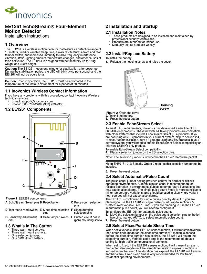
Inovonics EE1261 User manual

Inovonics

Inovonics EE1261 User manual

Inovonics EE1261 User manual

Inovonics

Inovonics EE1261 User manual

Inovonics EchoStream ES1260 User manual

Inovonics

Inovonics EchoStream ES1260 User manual

Inovonics EN1260EchoStream User manual

Inovonics

Inovonics EN1260EchoStream User manual

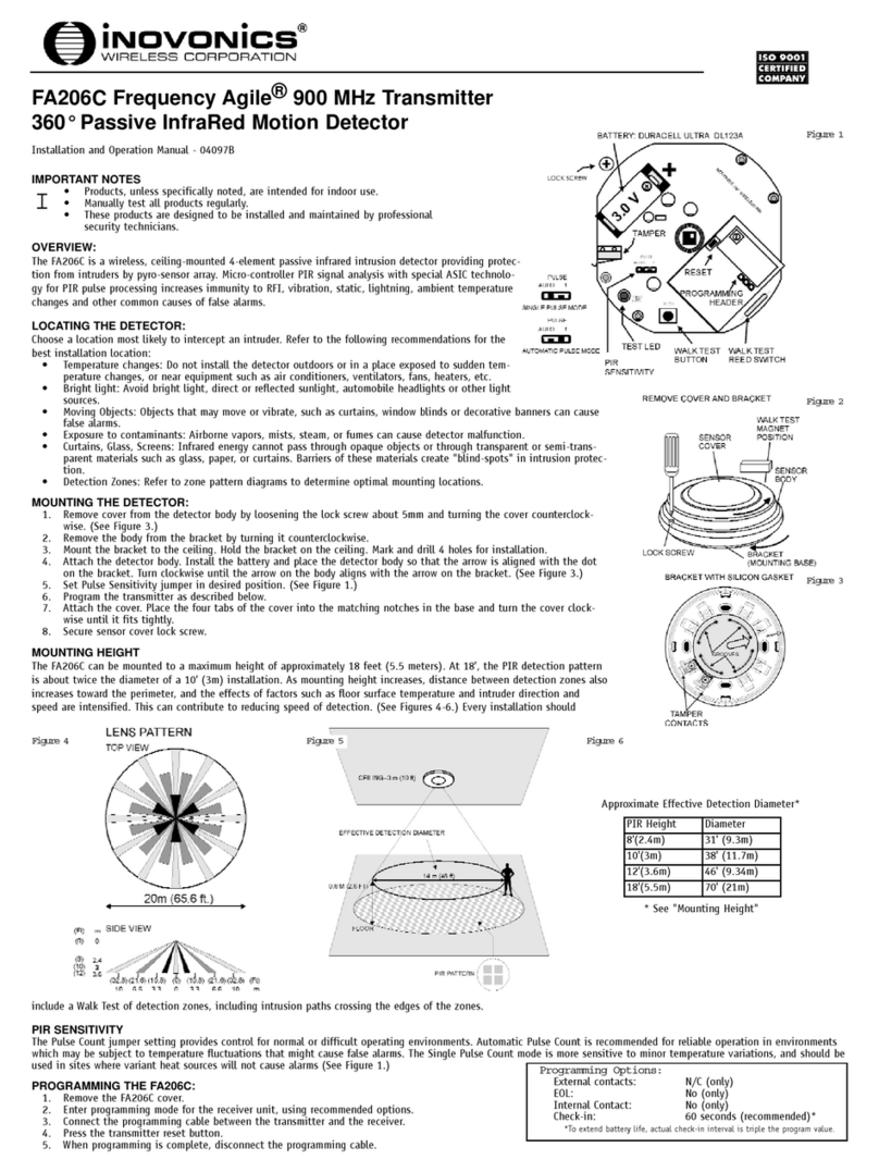
Inovonics Frequency Agile FA206C User manual

Inovonics

Inovonics Frequency Agile FA206C User manual

Inovonics EN1751 User manual

Inovonics

Inovonics EN1751 User manual

Inovonics Bosch Appliances Home Security System ES1260 User manual

Inovonics

Inovonics Bosch Appliances Home Security System ES1260 User manual

Inovonics EN1245 User manual

Inovonics

Inovonics EN1245 User manual

Inovonics EN1266 User manual

Inovonics

Inovonics EN1266 User manual

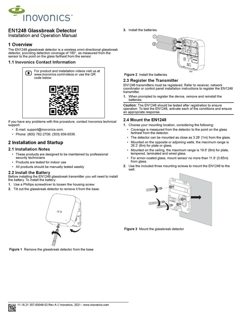
Inovonics EN1248 User manual

Inovonics

Inovonics EN1248 User manual

Inovonics EE1260 EchoStream User manual

Inovonics

Inovonics EE1260 EchoStream User manual

Inovonics EchoStream ES1265 User manual

Inovonics

Inovonics EchoStream ES1265 User manual

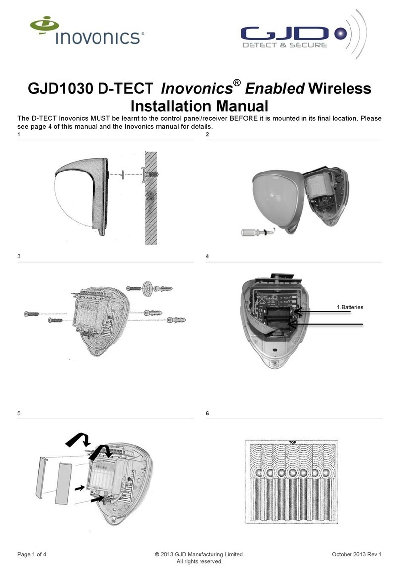
Inovonics D-TECT GJD1030 User manual

Inovonics

Inovonics D-TECT GJD1030 User manual

Inovonics EE1265 EchoStream User manual

Inovonics

Inovonics EE1265 EchoStream User manual

Popular Security Sensor manuals by other brands

Lamptime ST41 user manual

Lamptime

Lamptime ST41 user manual

Bosch ISC-PDL1-W18H installation instructions

Bosch

Bosch ISC-PDL1-W18H installation instructions

Risco Lumin8 4012 installation instructions

Risco

Risco Lumin8 4012 installation instructions

Bullard Magma Installation instruction

Bullard

Bullard Magma Installation instruction

Rehoo NDC-K user manual

Rehoo

Rehoo NDC-K user manual

Sygonix 6ZB-A806ST-Q1M operating instructions

Sygonix

Sygonix 6ZB-A806ST-Q1M operating instructions

NuAire 230PIR installation guide

NuAire

NuAire 230PIR installation guide

Polon-Alfa TUN-4046 Installation and maintenance manual

Polon-Alfa

Polon-Alfa TUN-4046 Installation and maintenance manual

Det-Tronics X5200 instructions

Det-Tronics

Det-Tronics X5200 instructions

B.E.G. LUXOMAT net PD4-M-DAA4G Installation and operating instruction

B.E.G.

B.E.G. LUXOMAT net PD4-M-DAA4G Installation and operating instruction

iRay Technology Luna1012X user manual

iRay Technology

iRay Technology Luna1012X user manual

ITALIANA SENSORI 8032-ISR023 Installation, operation and maintenance manual

ITALIANA SENSORI

ITALIANA SENSORI 8032-ISR023 Installation, operation and maintenance manual

DST ObservAir operating manual

DST

DST ObservAir operating manual

Leeo Smart Alert quick start guide

Leeo

Leeo Smart Alert quick start guide

BEA LZR-FLATSCAN SW quick guide

BEA

BEA LZR-FLATSCAN SW quick guide

Boltek LD-250 Installation and operator's guide

Boltek

Boltek LD-250 Installation and operator's guide

Aritech 700 series Installation sheet

Aritech

Aritech 700 series Installation sheet

Inficon HLD6000 Original operating instructions

Inficon

Inficon HLD6000 Original operating instructions

manuals.online logo
manuals.online logoBrands
  • About & Mission
  • Contact us
  • Privacy Policy
  • Terms and Conditions

Copyright 2025 Manuals.Online. All Rights Reserved.