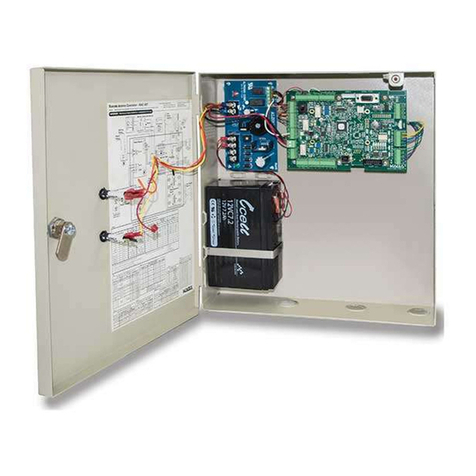
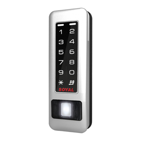
INOX Smart ISK-B300 Guide

ISK-B300
Smart All-Inclusive
Access Control Unit
Installation Manual
& User Guide
PM-ISK-UM
V08082023

ISK-B300 Installation Manual
and User Guide
Introduction � � � � � � � � � � � � � � � � � � � � � � � � � 3
Specications � � � � � � � � � � � � � � � � � � � � � � � � � 3
Features � � � � � � � � � � � � � � � � � � � � � � � � � � � 4
Template for ISK-B300 Smart Keypad � � � � � � � � � � � � � � � 5
Dimensions� � � � � � � � � � � � � � � � � � � � � � � � � � 7
Installation Instructions� � � � � � � � � � � � � � � � � � � � � 8
Colored Wire and Function Chart� � � � � � � � � � � � � � � � � 13
Device Category 1: Description and Wiring Diagram � � � � � � � � � 14
Device Category 2: Description and Wiring Diagram� � � � � � � � � 18
Operational Details � � � � � � � � � � � � � � � � � � � � � � 21
Basic Programming � � � � � � � � � � � � � � � � � � � � � � 22
Simplied Local Programming � � � � � � � � � � � � � � � � � � 23
Smart Initialization for DPS and DBM Sensors � � � � � � � � � � � 27
Wiegand Reader Mode � � � � � � � � � � � � � � � � � � � � � 29
Downloading and Setting Up the INOX Smart App � � � � � � � � � 30
Adding a Property to the App � � � � � � � � � � � � � � � � � � 34
Adding a Door to the App � � � � � � � � � � � � � � � � � � � 37
Pairing an ISK Access Control Keypad with the INOX Smart App � � � � 40
Pairing an ISK Access Control Keypad with a Wi-Fi / POE Gateway � � � 45

3
Introduction
The ISK-B300 is a Smart All-Inclusive Access Control Device that
supports multiple credential technologies including high-frequency
RFIDs, secured cloud-generated passcodes and mobile user credentials�
• Integrates with cloud-connected wireless communication
technology
• Provides intuitive and convenient smartphone access management
• Combines all functionalities of a controller, reader, monitor and user
management system
Specications
• Type: Back Lit Digital Touchscreen
• Style: Mullion
• Frequency: 13�56MHz / 125KHz
• Input Voltage: 12/24 V DC
• RF Output: 13�56MHz or 125KHz (reader) – 26-Bit Wiegand
• Read Interface: EM / MIFARE
• Read Range: ~3/4” – 2-1/2”
• Working Current: < 80mA (12v) ~ < 40mA (24v)
• Standby Current: < 30mA (12v) ~ < 20mA (24v)
• Passcode/PIN Length: 4 – 8 digits
• User Capacity: 2000: Mobile Credential 1000, RF/Passcode 1000
• Working Humidity: 0% to 98%
• Working Temperature: -20°F to 140°F
• Water Resistant: IP66

4
Features
• All-inclusive device: Reader, Controller, Keypad, and Monitor
• Multi-credential support: Passcodes, RFID FOB/Card/Wristband, and
Smart Phone
• Remote Access and Management via Wi-Fi and Low Energy
Bluetooth
• Cloud-based APP with a simple yet robust hierarchy of user roles
• Customizable permissions and levels for managing e-keys, users,
and devices
• Passage Mode: Enjoy free access during scheduled periods
• Privacy Mode: Keep privacy and security when needed
• Real-time Audit trail and backup email
• Door position sensor for monitoring open/closed status
• Latchbolt or Deadbolt Monitoring Sensor for monitoring locking
status
• Modern, water-resistant indoor/outdoor touchscreen keypad with
IP66 rating

5
Template for ISK-B300 Smart Keypad
6mm is the size recommended if
the anchors are being installed�
3mm is the size recommended
if its being installed into wood
(without anchors)

6
This page intentionally
left blank for removal with
ISK-B300 Installation Template

7
Dimensions
1-3/4”
(44�5mm)
5-7/8” (150mm)
7/8”
(22mm)

8
Installation Instructions
STEP 1
Prep the mounting location by drilling
holes as shown in the template�

9
Installation Instructions
STEP 2
Install anchors� Pull Molex wires
through the center hole and connect
according to wiring diagram� Keep any
unused wires isolated and protected�
Wall anchors are only
needed for concrete
installations�

10
STEP 3
Install screws to mount the sub-plate�
Installation Instructions

11
STEP 4
Connect the Molex from the ISK-B300 with the Molex
from the locking device�
Installation Instructions

12
STEP 5
Use the tool provided to x
the smart controller to the
sub-plate by installing the
tamper resistant screw into
the bottom of the unit�
Installation Instructions

13
Colored Wire and Function Chart
Wire Color Function Notes
Basic Standalone Wiring
Red DC+ 12-24VDC Power Input
Black GND Negative Pole of DC Power Input
Blue Relay NO Normally Open Relay Output (install
diode provided)
White Relay
Common Common Connection for Relay Output
Brown Relay NC Normally Closed Relay Output (install
diode provided)
Orange REX/Open Request to Exit (REX) Input
Pass-Through Wiring (Wiegand Reader or Controller)
Green/Black Data 0 Wiegand Output (Pass-Through) Data 0
White/Black Data 1 Wiegand Output (Pass-Through) Data 1
Advanced Input and Output Features
Grey Alarm Output Negative Contact for Alarm
Yellow DPS Input Door/Gate Contact Input (Normally
Closed)
Green DBM Input Input Status of Deadbolt/Latch Bolt

14
Device Category 1: Description and Wiring Diagram
The ISK-B300 Smart Access Controller can be connected to
Electromagnetic locking devices as EL (Fail Safe) or EU (Fail Secure).
These include but are not limited to:
• Electried Mortise Locks
• Electried Cylindrical Locks
• Electric Strikes
• Electried Exit Trims
• Maglocks
1� Connect Power to the
devices and power supply
with the correct voltage�
2� Connect the Common
and Normally Open (NO) or
Normally Closed (NC) with
the devices�
3� For Electrically-Unlocked
(EU)/Fail Secure devices,
connect NO and Common
lines�
4� For Electrically-Locked
(EL)/Fail Safe devices,
connect NC and Common
lines�
The default timing on the
closing circuits is 5 seconds�
In the Smart Mode, this timing
is adjustable from 5 seconds to
5 minutes using the Smart APP
in Device Settings�

15
Category 1 Wiring
DPS Output
Alarm Input
+
-

16
Category 1 Wiring (Cont�)
Power Input
NO
NC
REX/open
Input
DPS Input
DBM Input
Wiegand
Interface
Alarm Output

17
Category 1 Wiring (Cont�)
Reader Controller
Keypad
ISK-B300

18
Category 2 Wiring
Device Category 2: Description and Wiring Diagram
Motor-driven Mortise Lock, i.e. INOX PD9700
Black
Blue
Purple
Yellow
Green
Grey
Orange
Black
Black
Grey
Purple
White
Red
Red
Power Input
NO
REX/Open
Output
DPS Output
DBM Input
Alarm Output
Alarm Input
+
-

19
Category 2 Wiring (Cont�)
Power Input
NO
NC
REX/open
Input
DPS Input
DBM Input
Wiegand
Interface
Alarm Output

20
Category 2 Wiring (Cont�)
Reader Controller
Keypad
ISK-B300
Table of contents

