manuals.online logo
Brands
  1. Home
  2. •
  3. Brands
  4. •
  5. SMC Networks
  6. •
  7. Industrial Equipment
  8. •
  9. SMC Networks 55-CDU25 DCW3726W User manual

SMC Networks 55-CDU25 DCW3726W User manual

55-CU##-TF222-129EN
Page 1 of 2
Instruction Manual
Free Mount Cylinder
55-CDU25-*-DCW3726W
II 2GD
Ex h IIC T4/T4 Gb
-10°C ≤Ta≤ +60°C
Ex h IIIC T101°C/T121°C Db
Marking Description:
Specific Marking for Explosion Protection
II Equipment Group
2 Equipment Category
GD Environment (Gas and Dust)
Ex h Type of Protection –Constructional Safety ‘c’
IIC Gas Sub-Division
IIIC Dust Sub-Division
T Temp. Classification
Gb / Db Equipment Protection Level
X Special Conditions of Use
Ta Ambient Temperature Range
The intended use of this actuator is to convert the potential energy
provided by compressed air into a force which causes mechanical linear
motion.
Certifcate Number:
SMC22.0032X
Note: The X at the end of the certificate number represents that this product is
subject to “Special Conditions of Use”, please see Section 2.3.
1 Safety Instructions
These safety instructions are intended to prevent hazardous situations
and/or equipment damage. These instructions indicate the level of
potential hazard with the labels of “Caution,” “Warning” or “Danger.”
They are all important notes for safety and must be followed in addition
to International Standards (ISO/IEC)*1), and other safety regulations.
*1) ISO 4414: Pneumatic fluid power - General rules relating to systems.
ISO 4413: Hydraulic fluid power - General rules relating to systems.
IEC 60204-1: Safety of machinery - Electrical equipment of machines.
(Part 1: General requirements)
ISO 10218-1: Robots and robotic devices - Safety requirements for
industrial robots - Part 1: Robots.
•Refer to product catalogue, Operation Manual and Handling
Precautions for SMC Products for additional information.
•Keep this manual in a safe place for future reference.
Caution
Caution indicates a hazard with a low level of risk which, if
not avoided, could result in minor or moderate injury.
Warning
Warning indicates a hazard with a medium level of risk
which, if not avoided, could result in death or serious injury.
Danger
Danger indicates a hazard with a high level of risk which, if
not avoided, will result in death or serious injury.
Warning
•Always ensure compliance with relevant safety laws and
standards.
•All work must be carried out in a safe manner by a qualified person in
compliance with applicable national regulations.
2 Specifications
This product is suitable for use in Zones 1, 2, 21 and 22 only.
2.1 Product Specifications:
Refer to the operation manual for this product;
2 Specifications (continued)
Fluid
Air
Max. Operating Pressure
0.7 MPa
Min. Operating Pressure
0.05 MPa
Ambient & Fluid Temperature
-10°C to +60°C
Lubrication
Not Required
Operating Piston Speed
50 to 500 mm/s
Cushion
Rubber Bumper
Allowable Kinetic Energy
0.2 J
2.2 Production Batch Code:
The batch code printed on the label indicates the month and the year of
production as per the following table;
Production Batch Codes
Year
Month
2021
2022
2023
…
2027
2028
2029
…
Z
A
B
…
F
G
H
…
Jan
o
Zo
Ao
Bo
…
Fo
Go
Ho
…
Feb
P
ZP
AP
BP
…
FP
GP
HP
…
Mar
Q
ZQ
AQ
BQ
…
FQ
GQ
HQ
…
Apr
R
ZR
AR
BR
…
FR
GR
HR
…
May
S
ZS
AS
BS
…
FS
GS
HS
…
Jun
T
ZT
AT
BT
…
FT
GT
HT
…
Jul
U
ZU
AU
BU
…
FU
GU
HU
…
Aug
V
ZV
AV
BV
…
FV
GV
HV
…
Sep
W
ZW
AW
BW
…
FW
GW
HW
…
Oct
X
ZX
AX
BX
…
FX
GX
HX
…
Nov
y
Zy
Ay
By
…
Fy
Gy
Hy
…
Dec
Z
ZZ
AZ
BZ
…
FZ
GZ
HZ
…
2.3 Special Conditions of Use:
•Products are suitable for sub-divisions IIC and IIIC.
•Products are suitable for Zone 1, 2, 21 and 22 only.
2.3.1 Temperature Marking:
2.3.1.1 Standard Product:
•In the normal ambient temperature range (-10°C to +40°C) the product
is rated to temperature class T4 and has a maximum surface
temperature of 101°C.
•In the special ambienttemperaturerange (+40°C to +60°C) the product
is rated to temperature class T4 and has a maximum surface
temperature of 121°C.
3 Installation
3.1 Installation Warning
•Do not install the product unless the safety instructions have been read
and understood.
•Do not twist or bend the cylinder, or mount the product when subject
to tension.
•Do not use in an application where the product is stopped mid-stroke,
via an external stop.
•Do not use where cylinders are being synchronised to move a single
load.
•The product can be mounted in one of the following orientations.
Axial Mounting
(Body Tapped)
Vertical Mounting
(Body Through-hole)
Lateral Mounting
(Body Through-hole)
•When mounting the product use the hexagon socket head cap screw
and tightening torque defined below;
Bore [mm]
Screw Dia.
Tightening Torque
Ø 25
M5
5.10 ± 10%
3.2 Environment Warning
•Do not use in an environment where corrosive gases, chemicals, salt
water or steam are present.
•Do not use in an explosive atmosphere.
3 Installation - continued
•Do not expose to direct sunlight. Use a suitable protective cover.
•Do not install in a location subject to vibration or impact in excess of
the product’s specifications.
•Do not mount in a location exposed to radiant heat that would result in
temperatures in excess of the product’s specifications.
•Do not install in a location subject to vibration or impact in excess of
the product’s specifications.
•Do not use in a place subject to heavy vibration and/or shock.
•Do not usein wet environments, where water can remove the presence
of the lubrication.
•Do not use in case of heavy dusty environments where dust can
penetrate into the cylinder and dry the grease.
•Do not allow dust layers to build up on the cylinder surface and insulate
the product.
3.3 Piping Caution
•Before connecting piping make sure to clean up chips, cutting oil, dust
etc.
•When installing piping or fittings, ensure sealant material does not
enter inside the port. When using seal tape, leave 1 thread exposed
on the end of the pipe/fitting.
•Tighten fittings to the specified tightening torque.
PPN
Port Size
55-CDU25-*-DCW3726W
M5 x 0.8
3.4 Lubrication Caution
•SMC products have been lubricated for life at manufacture, and do not
require lubrication in service.
•If a lubricant is used in the system, refer to catalogue for details.
3.5 Basic Circuit
•Plugging one of the ports on the actuator is considered a non-intended
use, and could relate to an increase in maximum surface temperature
above what the product specification declares.
3.6 Electrical Connection
•The product should be grounded by the piston rod and the body in
order to createan electrically conductive pathto the system/application.
•Ground the product in accordance with applicable regulations.
•Do not pass an electrical current through the product.
4 Settings
Refer to the standard product operation manual for settings.
5 How to Order
Refer to customer drawing for ‘How to Order’.
6 Outline Dimensions
Refer to customer drawing for outline dimensions.
7 Maintenance
7.1 General maintenance Caution
•Not following proper maintenance procedures could cause the product
to malfunction and lead to equipment damage.
•If handled improperly, compressed air can be dangerous.
•Maintenance of pneumatic systems should be performed only by
qualified personnel.
•Before performing maintenance, turn off the power supply and be sure
to cut off the supply pressure. Confirm that the air is released to
atmosphere.
•After installation and maintenance, apply operating pressure and
power to the equipment and perform appropriate functional and
leakage tests to make sure the equipment is installed correctly.
•If any electricalconnections are disturbed during maintenance, ensure
they are reconnected correctly and safety checks are carried out as
required to ensure continued compliance with applicable national
regulations.
•Do not make any modification to the product.
•Do not disassemble the product, unless required by installation or
maintenance instructions.
•Do not use a product which looks or contains damage, this will
invalidate the certification. If damage is seen, please replace the
product immediately.
•Periodically check the product for any damage or rust appearing. This
could result in an increase in friction and lead to dangerous conditions.
Replace the whole actuator if any of these conditions appear.
•Periodically check the condition of the rod seal and forthe presence of
lubrication, where possible. If these areas appear to be dry, please
follow the lubrication procedure.
•The seals should be replaced when the air leakage is above the
allowable value given in the table below;
Allowable Leakage
Internal Leakage
10 cm3/ min (ANR)
External Leakage
5 cm3/ min (ANR)
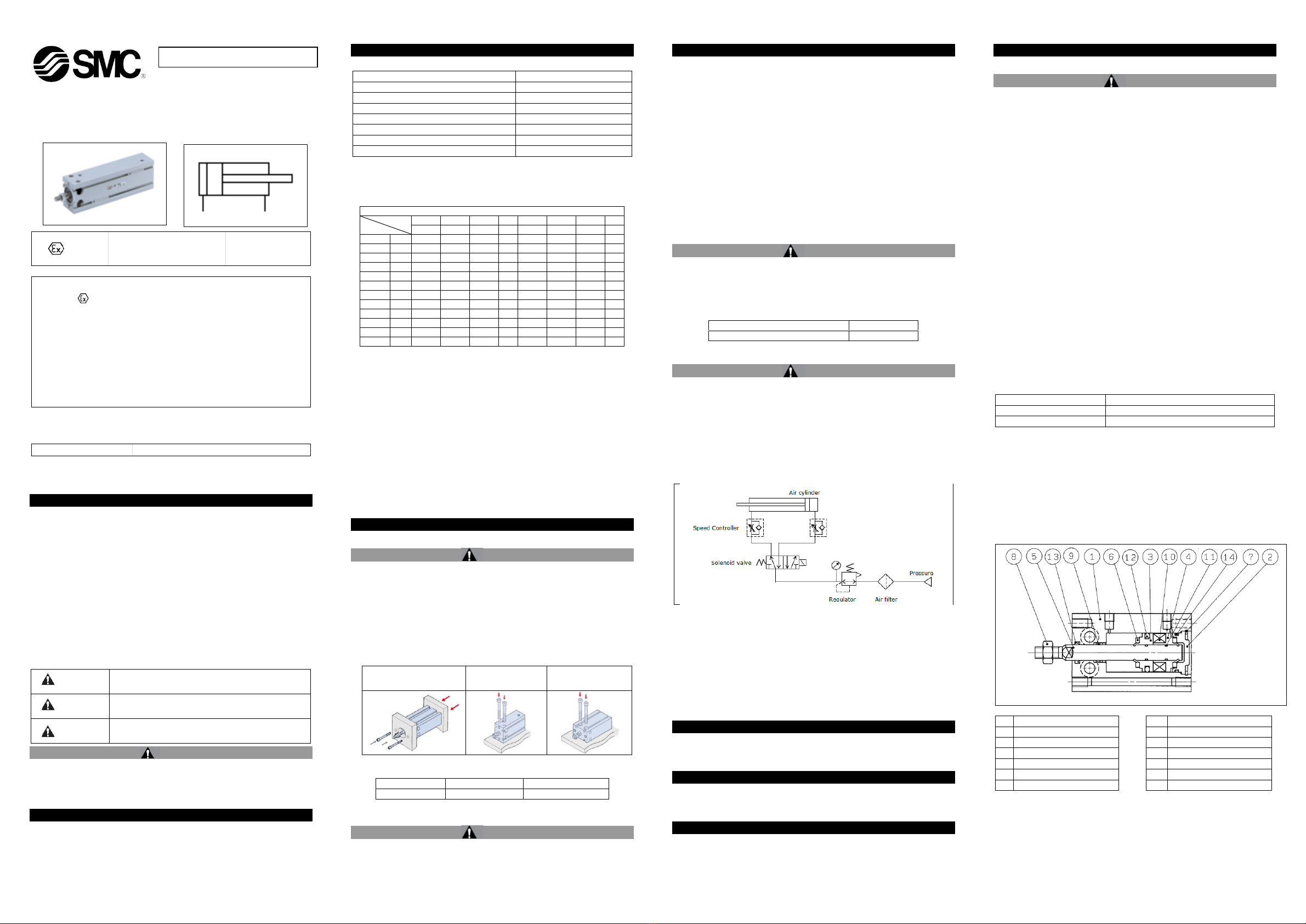
7.2 Disassembly Procedure
•Disassemble the cylinder, remove the old grease and place all the
parts on a clean cloth in a clean environment. Use a set of snap ring
pliers to remove the retaining ring (7) and then remove the head cover
(2). Remove the old piston seal (12), rod seal (13) and gasket (14),
using a fine screwdriver where necessary.
1
Cylinder Tube
8
Rod End Nut
2
Head Cover
9
Bushing
3
Piston
10
Magnet
4
Magnet Holder
11
Piston Gasket (NBR)
5
Piston Rod
12
Piston Seal (NBR)
6
Bumper
13
Rod Seal (NBR)
7
Retaining Ring
14
Gasket (NBR)
ORIGINAL INSTRUCTIONS
55-CU##-TF222-129EN
Page 2 of 2
7 Maintenance (continued)
7.3 Seal Replacement Part Numbers
Warning
Only use SMC seal kits as listed in the table below;
Description
Applicable
Bore [mm]
Part Number
55-CDU25-*-DCW3726W
Ø 25
CU25D-PS
7.4 Lubrication Procedure
•Apply lubricant to:
• The rod seal and the rod seal groove on the cover.
• The piston outer surface and piston seal groove.
• The piston seal and gaskets.
• The piston rod surface and cylinder tube internal surface.
•Lubricate the parts with the grease packs provided with the seal kit.
For additional grease use the grease pack listed below.
Product
Grease Pack Number
Weight [g]
Standard
GR-S-010
10
GR-S-020
20
The amount of lubricant to be applied is listed in the following table.
Bore [mm]
Required amount of
grease up to minimum
stroke [g]
For each additional
5mm Stroke [g]
Ø 25
Initial 5mm
0.12
0.015
7.5 Reassembly Procedure
Apply grease to the end of the piston rod, especially on the 30° chamfer
and on the flats. Insert with care the piston rod assembly into the
cylinder tube to prevent any damage to the rod seal, piston seal or tube
gasket.
Insert slowly the head cover collar assembly and then reassemble the
retaining ring to the rear side. Use appropriate pliers (tool for C-shape
snap ring) for installation.
Caution
When installing the snap ring, be aware that the snap ring may come off
the pliers and could result in operator injury or equipment damage. Also
make sure ring is firmly seated in ring groove.
•Checking assembly.
Make sure that no air is leaking from packing seals and that the cylinder
operates smoothly at minimum operating pressure. Check for cylinder
smooth movement and for air leakage.
8 Limitations of Use
8.1 Limited warranty and disclaimer/compliance requirements
Refer to Handling Precautions for SMC Products.
8.2 Obligations of the end-user
•Ensure the product is used within the specification outlined.
•Ensure that the maintenance periods are suitable for the application.
•Ensure any cleaning processes to remove dust layers are made with
the atmosphere in mind (e.g. using a damp cloth to avoid static build
up).
•Ensure that the application does not introduce additional hazards by
mounting, loading, impacts or other methods.
•Ensure that there is sufficient ventilation and air circulation around the
product.
•If the product is subject to direct heat sources in the application, they
should be shielded so that the actuator temperature stays within the
stated operating range. Danger
•Do not exceed any of the specifications listed in Section 2 of this
document as this will be deemed improper use.
•Air equipment has an air leakage during operation within certain limits.
Do not use this equipment when the air itself introduces additional
hazards and could lead to an explosion.
•Use only EX certified auto switches. These should be ordered
separately.
8 Limitations of Use (continued)
•Do not use this product in the presence of strong magnetic fields that
could generate a surface temperature higher than the product
specification.
•Avoid applications where the piston rod end and the adjoining part in
the application can create a possible ignition source.
•Do not install or use these actuators where there is the possibility for
the piston rod to impact foreign objects.
•In the event of damage or failure of any parts located in the vicinity
where this product has been installed, it is the responsibility of the user
to determine whether or not this has compromised the safety and
condition of this product and/or the application.
•External impact on the cylinder body could result in a spark and/or
cylinder damage. Avoid any application where foreign objects can hit
or impact the cylinder. In such situations the application should install
a suitable guard to prevent this occurrence.
•Do not use this equipment where vibration could lead to failure.
9 Product Disposal
This product shall not be disposed of as municipal waste. Check your
local regulations and guidelines to dispose this product correctly, in order
to reduce the impact on human health and the environment.
10 Contacts
Refer to www.smcworld.com or www.smc.eu for your local
distributor/importer.
URL : https:// www.smcworld.com (Global) https:// www.smc.eu (Europe)
SMC Corporation, 4-14-1, Sotokanda, Chiyoda-ku, Tokyo 101-0021, Japan
Specifications are subject to change without prior notice from the manufacturer.
© 2022 SMC Corporation All Rights Reserved.
Template DKP50047-F-085M

Other SMC Networks Industrial Equipment manuals

SMC Networks CKZT Series User manual

SMC Networks

SMC Networks CKZT Series User manual

SMC Networks ZL3 Series User manual

SMC Networks

SMC Networks ZL3 Series User manual

SMC Networks MGJ Series User manual

SMC Networks

SMC Networks MGJ Series User manual

SMC Networks EX600 Series User manual

SMC Networks

SMC Networks EX600 Series User manual

SMC Networks MWB-X3075 Series User manual

SMC Networks

SMC Networks MWB-X3075 Series User manual

SMC Networks 12-MGPL-Z Series User manual

SMC Networks

SMC Networks 12-MGPL-Z Series User manual

SMC Networks SGC Series User manual

SMC Networks

SMC Networks SGC Series User manual

SMC Networks EX600-SEN5 16 Series User manual

SMC Networks

SMC Networks EX600-SEN5 16 Series User manual

SMC Networks JAS-S Series User manual

SMC Networks

SMC Networks JAS-S Series User manual

SMC Networks CP96N Series User manual

SMC Networks

SMC Networks CP96N Series User manual

SMC Networks KF Series User manual

SMC Networks

SMC Networks KF Series User manual

SMC Networks JMHZ2-16D-X7500AC-KA Series User manual

SMC Networks

SMC Networks JMHZ2-16D-X7500AC-KA Series User manual

SMC Networks AW20 Series Quick start guide

SMC Networks

SMC Networks AW20 Series Quick start guide

SMC Networks ASB Series User manual

SMC Networks

SMC Networks ASB Series User manual

SMC Networks C96 Series User manual

SMC Networks

SMC Networks C96 Series User manual

SMC Networks EX260-VIL1 User manual

SMC Networks

SMC Networks EX260-VIL1 User manual

SMC Networks EX260-SCA1-X176 Manual

SMC Networks

SMC Networks EX260-SCA1-X176 Manual

SMC Networks CS2 125 Series User manual

SMC Networks

SMC Networks CS2 125 Series User manual

SMC Networks LEHR Series User manual

SMC Networks

SMC Networks LEHR Series User manual

SMC Networks MWB Series User manual

SMC Networks

SMC Networks MWB Series User manual

SMC Networks ZHP Series User manual

SMC Networks

SMC Networks ZHP Series User manual

SMC Networks HF2A-ASG V Series User manual

SMC Networks

SMC Networks HF2A-ASG V Series User manual

SMC Networks CKZ5N Series User manual

SMC Networks

SMC Networks CKZ5N Series User manual

SMC Networks ZXP7 Series User manual

SMC Networks

SMC Networks ZXP7 Series User manual

Popular Industrial Equipment manuals by other brands

Graco XM PFP 273231 Repair and parts

Graco

Graco XM PFP 273231 Repair and parts

YATO YT-23701 operating manual

YATO

YATO YT-23701 operating manual

NARGESA MX700 Instruction book

NARGESA

NARGESA MX700 Instruction book

Clemco SCW-2048 owner's manual

Clemco

Clemco SCW-2048 owner's manual

Stanley V Series user manual

Stanley

Stanley V Series user manual

ipf electronic IB05010H manual

ipf electronic

ipf electronic IB05010H manual

Fontaine 3000 series ASSEMBLY, DISASSEMBLY AND TROUBLESHOOTING INSTRUCTIONS

Fontaine

Fontaine 3000 series ASSEMBLY, DISASSEMBLY AND TROUBLESHOOTING INSTRUCTIONS

Trane RTHD installation instructions

Trane

Trane RTHD installation instructions

SICK DKV60 operating instructions

SICK

SICK DKV60 operating instructions

Harris DataSmart 763 Installation & operation manual

Harris

Harris DataSmart 763 Installation & operation manual

probst BSZ-H-5.1 operating instructions

probst

probst BSZ-H-5.1 operating instructions

Endo THB-15A user manual

Endo

Endo THB-15A user manual

ABB HT567732 Operation manual

ABB

ABB HT567732 Operation manual

MSW MSW-OBG40 user manual

MSW

MSW MSW-OBG40 user manual

Crosby Loadblock Plus operating instructions

Crosby

Crosby Loadblock Plus operating instructions

Stefan Mayer Instruments MK-3 user manual

Stefan Mayer Instruments

Stefan Mayer Instruments MK-3 user manual

RITE-HITE VBR-300 Dok-Lok owner's manual

RITE-HITE

RITE-HITE VBR-300 Dok-Lok owner's manual

Zoeller MEDIUM X5 operating manual

Zoeller

Zoeller MEDIUM X5 operating manual

manuals.online logo
manuals.online logoBrands
  • About & Mission
  • Contact us
  • Privacy Policy
  • Terms and Conditions

Copyright 2025 Manuals.Online. All Rights Reserved.