ARCURE BLAXTAIR 3 User manual

IR®3
Installation instructions

23/04/2019 2/71
Summary
PART 1 : INSTALLATION ..................................................................................................................4
1 EQUIPMENT DESCRIPTION....................................................................................................4
1.1 BLAXTAIR®KIT DESCRIPTION..................................................................................................... 4
1.2 DIMENSIONS.............................................................................................................................6
1.3 OPTIONS ..................................................................................................................................7
1.4 EQUIPMENT REQUIRED ..............................................................................................................8
2 RECOMMENDED SEQUENCE OF OPERATIONS..................................................................9
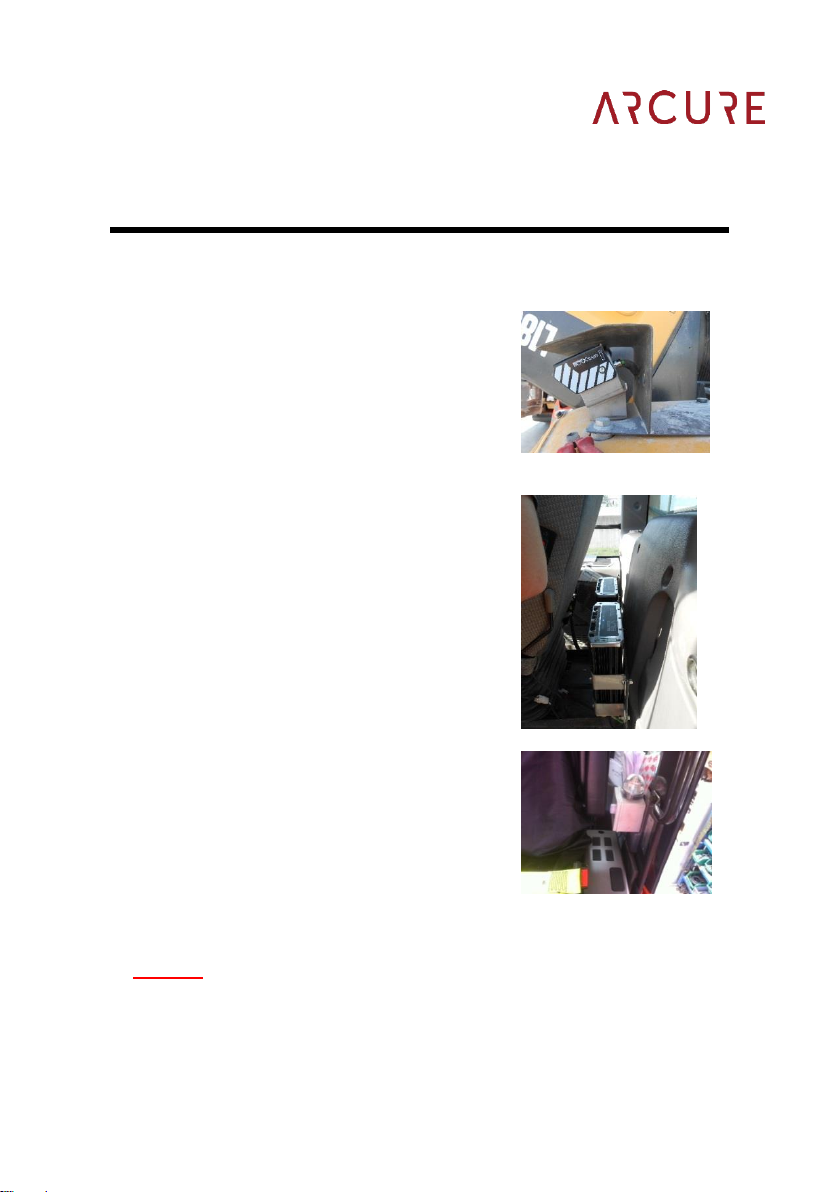
3 POSITIONING THE BLAXTAIR® SENSOR HEADS..............................................................11
4 INSTALLING THE BLAXTAIR® SENSOR HEADS.................................................................13
5 ROUTING THE SENSOR HEAD CABLES..............................................................................14
6 POSITIONING MONITORS AND OPTIONAL ADD-ONS .......................................................16
6.1 BLAXTAIR® MONITOR ...........................................................................................................16
6.2 OPTIONAL ADD-ON BLAXTAIR/BLAXTAIRVIEW®AND/OR SINGLE MONITOR OPTION........................17
6.3 LED (OPTION)BXT-LED ........................................................................................................21
6.4 BUZZER BOXES (OPTIONAL)BXT-BUZ AND LED+BUZZER (OPTIONAL)BXT-BUZ-LED...............22
6.5 SPLITTER BUZZER (BXT-SPLIT-BUZ).....................................................................................24
6.6 ACCESSORY CABLE (BXT-OPT)..............................................................................................25
7 POWERING THE SYSTEMS...................................................................................................26
8 POSITIONING THE BLAXTAIR® PROCESSING UNIT .........................................................28
9 CONNECTING THE ACCESSORIES TO THE BLAXTAIR® PROCESSING UNIT..............30
9.1 CONNECTING THE CABLES TO THE PROCESSOR ........................................................................30
9.2 MR180 ONLY .........................................................................................................................30
10 INITIAL START-UP..................................................................................................................31
11 MEASURING THE POSITION OF THE BLAXTAIR® HEADS................................................32
12 SYSTEM CONFIGURATION ...................................................................................................34
PART 2 : CONFIGURATION............................................................................................................35
1 FOREWORD............................................................................................................................35
2 LAUNCHING THE CONFIGURATION TOOL .........................................................................36
2.1 EQUIPMENT REQUIRED ............................................................................................................36
2.2 LAUNCH..................................................................................................................................36
2.3 SELECTING THE CONFIGURATION MODEL...................................................................................38
3 MODEL CUSTOMISATION .....................................................................................................39
3.1 INSTALLER LANGUAGE AND KEYBOARD......................................................................................39
3.2 USER LANGUAGE.....................................................................................................................40
3.3 ADVANCED SETUP...................................................................................................................40
3.4 VEHICLE SETUP.......................................................................................................................41
3.5 SETUP OF SHUTDOWN DELAY...................................................................................................42
3.6 SETUP OF DATE &TIME ............................................................................................................43
3.7 SETUP OF THE SENSOR HEADS.................................................................................................44
3.8 REAR-VIEW MIRROR MODE.......................................................................................................46
3.9 POSITION AND ORIENTATION OF THE SENSOR HEADS ON THE MACHINE........................................47
3.10 ALARM TYPES .........................................................................................................................48
3.11 DETECTION ZONES (TYPE,DIMENSIONS) ...................................................................................51
3.11.1 DESCRIPTION OF DETECTION ZONES ..................................................................................51
3.11.2 CHANGING THE DETECTION ZONES SHAPE AND SIZE ............................................................52
3.11.3 PHYSICAL FEATURES OF THE DETECTION ZONES.................................................................53
4 OPTIONS .................................................................................................................................56
4.1 « SHARP SLOPES ».................................................................................................................57

23/04/2019 3/71
4.2 « NEAR DETECTION »..............................................................................................................57
4.3 « CLUTTERED ENVIRONMENT »................................................................................................57
5 COPY OF CONFIGURATION..................................................................................................58
5.1 REQUIRED MATERIALS .............................................................................................................58
5.2 COPYING THE CONFIGURATION.................................................................................................59
5.3 TO INSTALL THE CONFIGURATION INTO ANOTHER PU.................................................................61
6 RESOLVING POTENTIAL INCONSISTENCIES.....................................................................63
6.1 ZONES ...................................................................................................................................63
7 VALIDATION OF THE CONFIGURATION..............................................................................65
7.1 CHECK THE USER LANGUAGE ...................................................................................................65
7.2 CHECK MIRROR-VIEW MODE.....................................................................................................65
7.3 CHECK THE HEIGHT AND ANGLE OF THE SENSOR HEADS.............................................................65
7.4 CHECKING THE MACHINE’S TOP VIEW AND DETECTION ZONES .....................................................67
7.5 CHECK THE ALARM TYPES........................................................................................................67
8 VALIDATION AND RESOLVING PROBLEMS........................................................................68
8.1 FINAL TEST.............................................................................................................................68
8.2 ARCURE CUSTOMER SUPPORT .................................................................................................69

23/04/2019 4/71
PART 1 : INSTALLATION
1 Equipment description
1.1 Blaxtair® Kit description
Blaxtair® is composed of :
Part
Variations
Components
Fastenings
Blaxtair ® Sensor
Head (SH)
Colour
Black and white
4x M5x15 BTR
4 x lock washers
4 x flat washers
Mounting kit
4x M8x25 HEX
4 x M8 nuts
4 x M8 lock washers
8 x M8 flat washers
4x M8x25 BTR
4 x M8 nuts
8 x M8 flat washers
4 x M8 lock washers
3x M8x40 HEX
3 x M8 nuts
3 x M8 lock washers
6 x M8 flat washers
Cap
Standard

23/04/2019 5/71
Cap
Reinforced
Processing unit
(PU)
With internal hard
drive (video
recorder)
Or
Without hard drive
Fixing brackets x 4
4x M5x12 BTR
4 x M5 flat washers
4 x M5 lock washers
5m 6 wire power cable
Fuse holder
1 x 7.5A fuse
2 x 2A fuses
6 x Insulated Crimp
terminals
PU/SH cable
Length options:
3m
5m
10m
Standard Blaxtair
Monitor
3 possible options
to replace the
standard:
Wireless,
multicamera or
waterproof
Adhesive bracket
5m PU/Screen cable

23/04/2019 6/71
1.2 Dimensions

23/04/2019 7/71
1.3 Options
The following options are available:
•One or more multi coloured LEDs
•One or more alarm sounder boxes
•A splitter for multiple accessories
•A video signal converter
•Voice buzzer

23/04/2019 8/71
1.4 Equipment required
•Regular workshop tools
•Digital spirit level or relevant
smartphone app
•Drill
•Various fasteners
•Split or non-spilt sheath (min. 12mm)
•A length of single core cable for reverse
connection

23/04/2019 9/71
2 Recommended sequence of operations
•Carefully select the location for the
head, following the configuration sheet
provided and precautions given in
section 3
•Select the location for the Processor,
bearing in mind the precautions given
in section 8
•Select the locations for any optional
items, bearing in mind the precautions
given in section 6
Disconnect the machine’s main power prior to installation
DO NOT connect or disconnect any cables when the system is
‘powered up’
Any damage caused by the above will not be covered under
warranty
•

23/04/2019 10/71
•Install the Sensor Head (section 3)
•Route the green Sensor Head
cable back to the Processor
location (section 5)
•If no ‘reverse signal’ is available
near the Processor location it is
advisable to run a separate wire
along with the Head cable as the
Head will be situated close to a
reverse light or ‘backup’ alarm
•Install the Power cable (section 7)
•Mount the Monitor and any optional
Accessories (section 6)
•Temporarily attach all cables to the
Processor (section 9)
•Reconnect the power and turn
the ignition on. The Processor will
emit an audible signal to confirm
power is present
•Check that the system ‘starts up’ correctly (section 10)
•Power down the system then
finish installing the Processor
making sure that any excess
cables are neatly stored out
of sight

23/04/2019 11/71
3 Positioning the BLAXTAIR® Sensor Head
To achieve an optimal detection performance, the following rules must
always be respected:
oThe Sensor Head must be installed at a height between 1.0m and
2.4m with respect to the ground level.
oAny pedestrian must appear on the monitor in full when between
1.2m and 7.0m away from the Sensor Head. The Sensor Head
should therefore be positioned in accordance with the
corresponding table below.
oThe Sensor Head cables should never be connected or
disconnected when the Processor is turned on
Head height
(m)
1.0
1.2
1.4
1.6
1.8
2.0
2.2
2.4
Head angle
(« x»,°)
0
-6
-11
-17
-23
-29
-31
-33

23/04/2019 12/71
•No part of the machine shall obstruct the field of view.
•The Blaxtair® head must not have a slope angle (angle « z »,°) when
mounted. Maximum tolerance is of +/- 2°.
•The Blaxtair® head must not be exposed to
oimpacts
ocorrosive elements
omiscellaneous projected matter (mud, gravel, tarmac, etc.)
•The Blaxtair® Sensor Head must not be installed:
oonto a vibrating component or on a mounting that increases
vibrations, etc.
oonto a moving part of the machine: the height and angle of
the Blaxtair® Sensor Head must remain consistent
oonto a fragile mount (thin metal plate, etc.)
oimmediately next to a very hot component
•The cables between the Sensor Head and Processor must not be
routed near to any component heating to above 70 °C. e.g. exhausts
•The Sensor Headcables should never be connected or disconnected
when the Processor is turned on.

23/04/2019 13/71
4 Installing the BLAXTAIR® sensor heads
•Fix the Heads securely to their predetermined location, bearing in
mind the weight of the Head and the mounts. Use a reinforced
backplate if necessary.

23/04/2019 14/71
5 Routing the sensor head cables
•When installing cables on the machine, start from the Head working
towards the Processor. Do not remove the protective cap fitted to the
plug before routing it. Cable tie the plug in a plastic bag when routing
it through the machine to stop ingress of dirt, oil, etc.
•Cables must be protected by cable glands when routed through a
partition.
•Follow existing cables routes as far as possible.
Cables should never be routed in contact or near heat sources
(e.g. exhaust pipe, radiator, etc.).
Cables should never pass in front of hatches or openings

23/04/2019 15/71
•Protect the Head cable all the way along the channel up to the
Processor with the aid of a split sheath.
•Follow the original or already installed cables. The cables should be
secured at regular intervals (at least every 20cm) along the entire
length with cable ties. No cables should be able to move freely.
•Tidy away and secure unused lengths of cable, in a compartment,
for example.

23/04/2019 16/71
6 Positioning monitors and optional add-ons
6.1 BLAXTAIR® monitor
Never plug-in or unplug the monitor when the system is working. If
necessary, turn off the whole system fully before working on the
monitor.
•The monitor must be installed in accordance with the following
conditions:
oPreferably, the monitor should be positioned in line with the
mirrors;
oThe monitor must not obstruct the driver’s view;
oThe monitor must be easily visibly by the operator;
oMount the monitor holder with self-tapping screws or bolts
DO NOT infringe ROPS or FOPS
Drilling or screwing into structural areas is strictly forbidden
If in any doubt, contact the manufacturer

23/04/2019 17/71
6.2 Optional add-on Blaxtair/BlaxtairView® and/or
single monitor option
The system is composed of:
•One or more cameras with:
oTheir brackets,
oThe extension lead between monitor and camera (5, 10, 15 or
20m).
•A specific multi-camera monitor including:
oA power and interconnection harness,
oBrackets,
oA cap,
oA remote.
•A video signal converter including:
oA case fitted with two connectors
oA 1m cable connecting the Processor to the case,
oA 5m cable connecting the case to the screen,
oA mounting kit,
oAs an optional extra, a Blaxtair outlet accessory cable, enabling
modification to screen display priorities.

23/04/2019 18/71
The system’s connection diagram is as follows:
In this example (MR180 single monitor), the brown wire of the accessory cable
(BXT-OPT) will give 12V to the monitor when Blaxtair® raises an alarm, so
the corresponding view will be displayed in priority on the screen.
1
2
BXT-DISP-MC Multi camera monitor Blaxtair ®
BXT-OPT accessory cable Blaxtair ®
BXT-CVT2 Converter video Blaxtair ®
With specific set of cables
BXT-PU-… Processing unit Blaxtair ®
Power of monitor:
Red = ignition
Black: Ground

23/04/2019 19/71
•Each camera connected corresponds to a trigger. For example, the
brown "Back" trigger corresponding to the "Back" camera and can
be connected to the vehicle's reversing system so as to display the
image from the "Back" camera when the machine is put into reverse
gear.
•If no triggers are connected, the monitor remains in standby mode.
For the monitor to display the camera view without a trigger, you will
need to select a setting with the remote control.
•After removing the protective plastic tab from the remote control
press the « menu » button and you will see the image below :

23/04/2019 20/71
•Use the buttons below to navigate :
« Up/Dn » for up/down
Right hand « Vol » to select a line.
It is possible to change the language from the "OSD" menu.
To display the camera(s) that should be active on power up, change the
"activated mode" line in the "System" menu.
Note: if required, the beeps can be turned off in this menu.
Examples:
•Select "Dual 1" for a MR180 mono-monitor.
•For a system with a front BxtView camera, the entry used on the
camera should be set to match the connector attached to the camera
(BxtView camera connected to "right/blue", activated mode on
"Right").
Other manuals for BLAXTAIR 3
1
Table of contents
Popular Industrial Equipment manuals by other brands

Aerotech
Aerotech VascuLathe ASR Series user manual

CHIEF
CHIEF LW46UxP installation instructions

Task Force Tips
Task Force Tips Extend-A-Gun XG12 Installation and operating instructions

Dover
Dover Destaco Ronohand RP Series Service manual

ABB
ABB HT609937 Operation manual

Zodiac
Zodiac Heatline in case Series Instructions for installation and use