INOXPA LR Series Manual

INSTALLATION, SERVICE AND MAINTENANCE INSTRUCTIONS
SIDE-ENTRY AGITATOR
LR / LM
Manual Original
20.025.30.01EN
(0) 2019/04
20.025.32.0001

20.025.30.02EN
(0) 2019/02
(1) The serial number may be preceded by a slash and by one or two alphanumeric characters
20.025.30.02EN
(0) 2019/02
EC Declaration of Conformity
We,
INOXPA, S.A.U.
Telers, 60
17820 –Banyoles (Girona)
Hereby declare under our sole responsibility that the machine
LR/LM side entry agitator
From serial number IXXXXXX to IXXXXXX (1) / XXXXXXXXXIIN to XXXXXXXXXIIN (1)
Fulfills all the relevant provisions of the following directive:
Machinery Directive 2006/42/EC
Low Voltage Directive 2014/35/EU
Electromagnetic Compatibility Directive 2014/30/EU
Applicable harmonized standards:
UNE-EN ISO 12100:2012
UNE-EN 14120:2016
The technical file has been prepared by the signer of this document in INOXPA.
David Reyero Brunet
Technical Office Manager
Banyoles, 7th February, 2019

INOXPA S.A.U. 20.025.30.01EN · (0) 2019/04 3
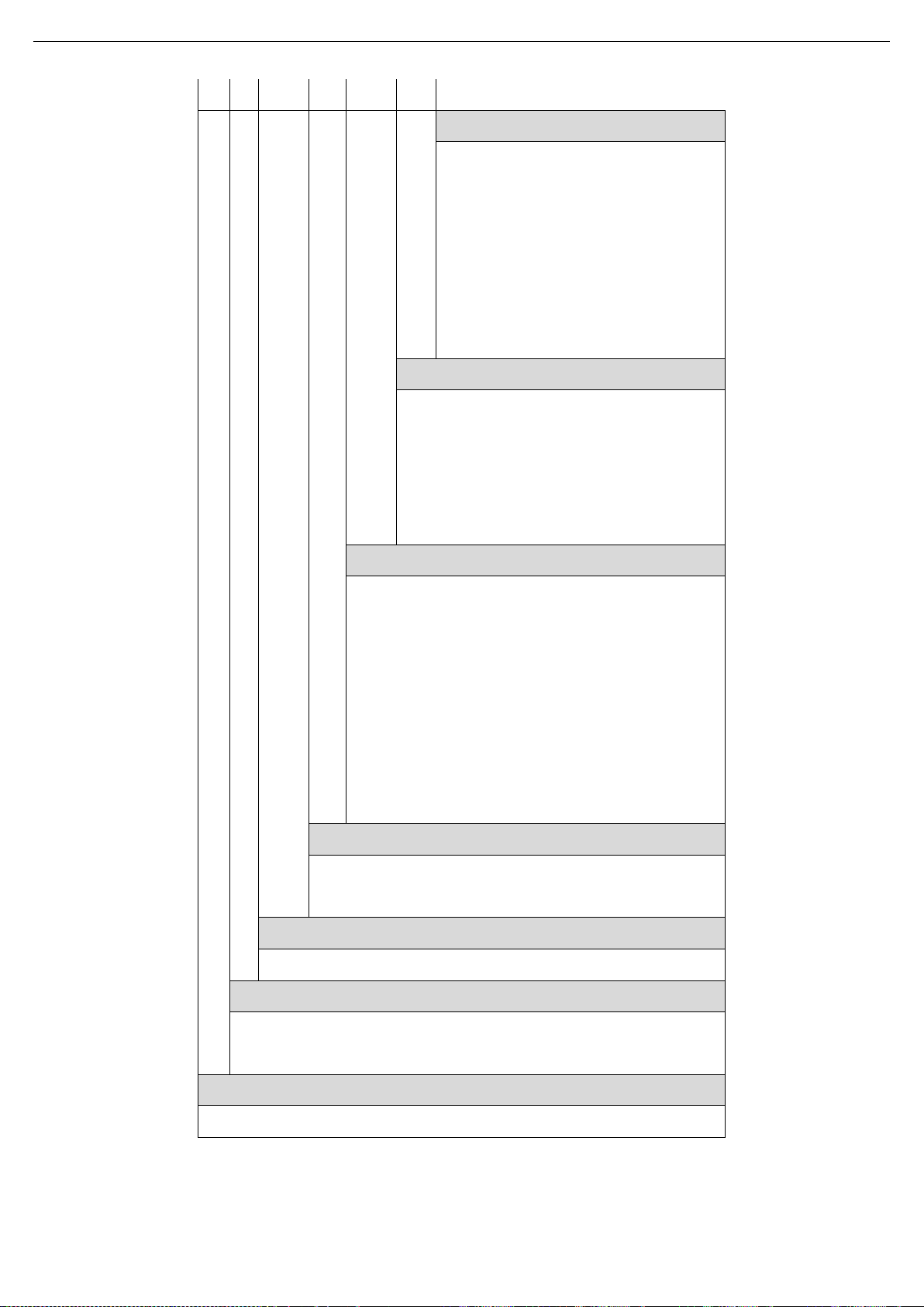
1. Table of Contents
1. Índex
2. Generalities
2.1.Instructions manual.......................................................................................................................................4
2.2.Compliance with the instructions ..................................................................................................................4
2.3.Warranty........................................................................................................................................................4
3. Safety
3.1.Warning symbols...........................................................................................................................................5
3.2.General safety instructions ...........................................................................................................................5
4. General Information
4.1.Description....................................................................................................................................................7
4.2.Operating principle........................................................................................................................................7
4.3.Application.....................................................................................................................................................7
5. Installation
5.1.Reception of the agitator...............................................................................................................................8
5.2.Identification of the agitator...........................................................................................................................8
5.3.Transport and storage.................................................................................................................................11
5.4.Location.......................................................................................................................................................11
5.5.Electrical installation ...................................................................................................................................12
5.6.Assembly.....................................................................................................................................................12
6. Start-up
7. Troubleshooting
8. Maintenance
8.1.General considerations...............................................................................................................................16
8.2.Maintenance................................................................................................................................................16
8.3.Lubrication...................................................................................................................................................16
8.4.Spare parts..................................................................................................................................................16
8.5.Conservation...............................................................................................................................................16
8.6.Disassembly and assembly of the agitator .................................................................................................17
9. Technical Specifications
9.1.Materials......................................................................................................................................................19
9.2.Other features.............................................................................................................................................19
9.3.Weights.......................................................................................................................................................19
9.4.Dimensions of LR side-entry agitator..........................................................................................................20
9.5.Dimensions of LM side-entry agitator .........................................................................................................21
9.6.Exploded drawing and parts list of LR side-entry agitator ..........................................................................22
9.7.Exploded drawing and parts list of LM side-entry agitator..........................................................................23
Generalities
4 INOXPA S.A.U. 20.025.30.01EN · (0) 2019/04
2. Generalities
2.1. INSTRUCTIONS MANUAL
This manual contains information about the reception, installation, operation, assembly, disassembly and
maintenance of the LR/LM side-entry agitator.
Carefully read the instruction prior to starting the agitator, familiarize yourself with the installation, operation and
correct use of the agitator and strictly follow the instructions. These instructions should be kept in a safe location
near the installation area.
The information published in the instruction manual is based on updated data.
INOXPA reserves the right to modify this instruction manual without prior notice.
2.2. COMPLIANCE WITH THE INSTRUCTIONS
Not following the instructions may impose a risk for the operators, the environment and the machine, and may
result in the loss of the right to claim damages.
This non-compliance may result in the following risks:
failure of important machine/plant functions,
failure of specific maintenance and repair procedures,
possible electrical, mechanical and chemical hazards,
risk to the environment due to the type of substances released.
2.3. WARRANTY
Any warranty will be void immediately and lawfully and, additionally, INOXPA will be compensated for any civil
liability claims submitted by third parties, in the following cases:
the service and maintenance work have not been carried out in accordance with the service instructions,
the repairs have not been carried out by our personnel or have been carried out without our written
authorisation,
modifications have been carried out on our material or equipment without written authorisation,
the parts or lubricants used are not original INOXPA parts and products,
the material or equipment has been improperly used, has been used negligently, or has not been used
according to the instructions and their intended.
The General Conditions of Delivery already in your possession are also applicable:
The machine may not undergo any modification without prior approval from the manufacturer.
For your safety, only use original spare parts and accessories.
The usage of other parts will relieve the manufacturer of any liability.
Changing the service conditions can only be carried out with prior written authorization from
INOXPA.
Please do not hesitate to contact us in case of doubts or if further explanations are required regarding
specific data (adjustments, assembly, disassembly, etc.).
Safety
INOXPA S.A.U. 20.025.30.01EN · (0) 2019/04 5
3. Safety
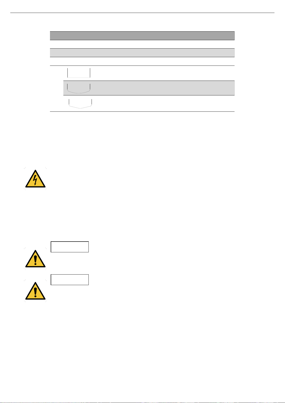
3.1. WARNING SYMBOLS
Safety hazard for people in general and/or for equipment
Electric hazard
Important instruction for the protection of the equipment and its functions
3.2. GENERAL SAFETY INSTRUCTIONS
Read the instruction manual carefully before installing and starting the agitator. Contact INOXPA in
case of doubt.
3.2.1. During the installation
The Technical Specifications of chapter 9.
The installation and use of the agitator should always be in accordance with applicable regulations
in regard to health and safety.
Before starting up the agitator, check that it is properly anchored and its shaft is perfectly aligned.
Incorrect alignment and/or excessive stress during coupling can cause serious mechanical
problems in the agitator.
Take all possible precautions when lifting the agitator. Always use properly attached slings when
moving the agitator with a crane or other lifting device.
Keep the motor and the switchboard under control, particularly in areas where there is a risk of fire
or explosion.
When cleaning, do not spray directly on the engine.
Do not disassemble the agitator until the switchboard has been disconnected. Remove the fuses
and disconnect the power cable supplying the motor.
All electric work should be carried out by specialised personnel.
3.2.2. During operation
The Technical Specifications of chapter 9 should always be observed. Under no circumstances can
the specified limit values be exceeded.
Before starting up the agitator, remove all the tools used during the assembly.
Do not operate the agitator when the rotating parts are not equipped with their guards or are not
properly assembled.
The agitator has rotating parts. Do not place hands or fingers in the agitator while it is operating.
This may cause serious injuries.
Do not touch the parts of the agitator that are in contact with the fluid when in operation. When the
agitator operates with hot fluids (temperatures above 50ºC), there is a risk of skin burning. In such
cases, collective-protection means (in this order or priority: separation, protective screen, heat-
insulating material) or, in the absence of this, individual protection gear (gloves) must be used.
ATTENTION
Safety
6 INOXPA S.A.U. 20.025.30.01EN · (0) 2019/04
The agitator and its installation can generate sound levels above 85 dB(A) under unfavourable
operating conditions. In such cases, the operators must use devices for protection against noise.
3.2.3. During maintenance
The Technical Specifications of chapter 9 shall always be observed.
The agitator cannot operate without fluid. Standard agitators are not designed to work during the
filling or emptying of tanks.
The maximum operating conditions of the agitator should not be exceeded. Nor should the
operating parameters for which the agitator was initially designed be modified without written
authorisations from INOXPA.
Do not leave loose parts on the floor.
Do not disassemble the agitator until the switchboard has been disconnected. Remove the fuses
and disconnect the power cable supplying the motor.
All the electric work should be carried out by specialised personnel.

General Information
INOXPA S.A.U. 20.025.30.01EN · (0) 2019/04 7
4. General Information
4.1. DESCRIPTION
The LM agitator range includes the side-entry agitators with the agitator shaft fixed directly onto the motor and
the LR agitator range includes side-entry agitators with the agitator shaft fixed directly onto the gear motor. The
lantern connected to the tank has a base plate made of stainless steel. The agitator shaft is guided by a
bearing. The sealing of the shaft is carried out mechanically and is standardized according to DIN 24960.
The standard mixing element is the marine propeller type 10.
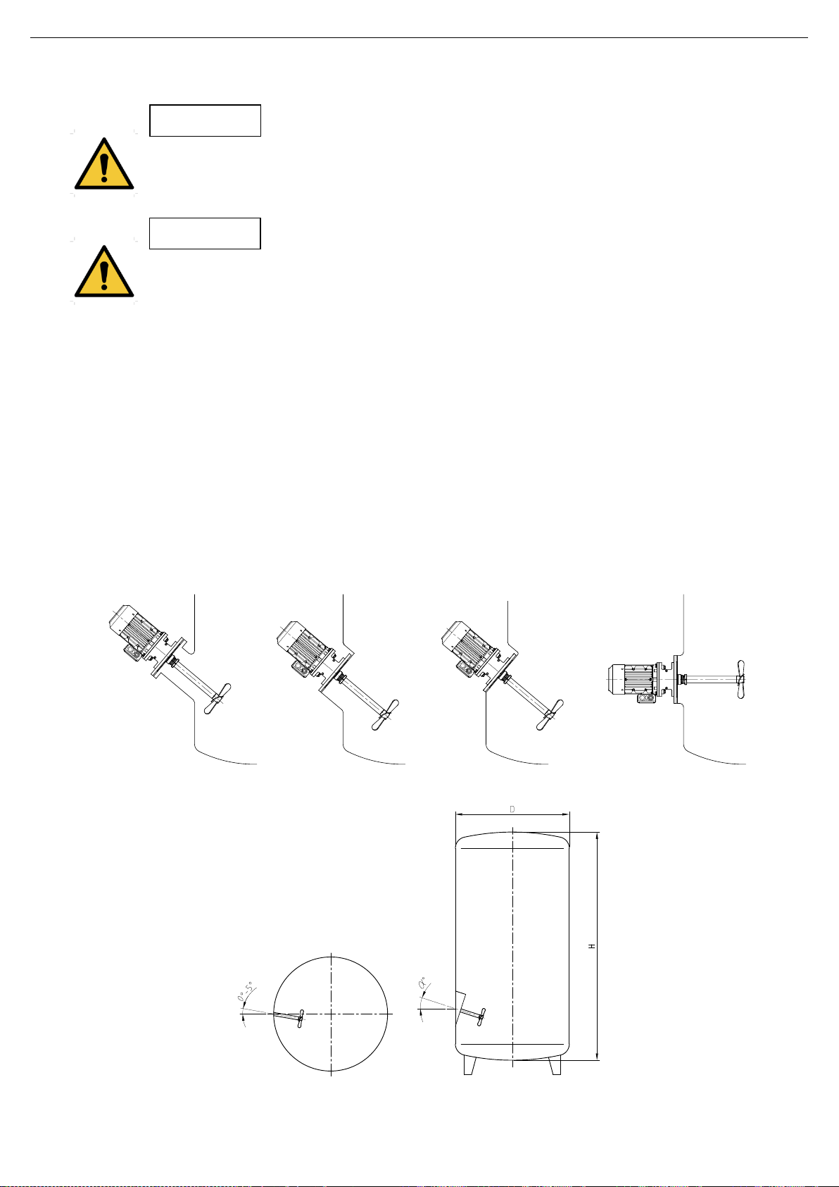
4.2. OPERATING PRINCIPLE
The LR agitators are driven by geared motors and the LM agitators are provided with direct motors.
These agitators are installed in a slanted position.
The rotation of the propeller creates a flow that impells the product to the bottom of the tank and then raises up
to the surface along the wall apposite to the agitator. The effect is promoted if the bottom is curved.
The agitator is installed decentralized to enhance the circular flow. Thus a complete homogenization of the
product is achieved.
4.3. APPLICATION
This lightweight range allows mixing and blending processes to be carried out in open and closed tanks with a
variable viscosity between 1 and 1000 cPs.
The main application is agitation of low viscosity products like wine, oil, milk, beer, alcohol, etc. in large volume
tanks.
Each agitator has performance limits. The agitator was selected for a given set of mixing conditions
when the order was placed. INOXPA shall not be held responsible for any damage that might be
suffered or malfunctioning of the equipment of the information provided by the buyer is incomplete
or incorrect (e. g. nature of the fluids or installation details).

Installation
8 INOXPA S.A.U. 20.025.30.01EN · (0) 2019/04
5. Installation
5.1. RECEPTION OF THE AGITATOR
INOXPA is not liable for any deterioration of the material caused by its transport or unpacking.
Visually check that the packaging has not been damaged.
If the agitator is supplied without a drive or other element, the purchaser shall be responsible for its
assembly, installation, start-up and operation.
When receiving the agitator, check the packaging and its content to ensure that it matches the delivery note.
INOXPA packs the agitator in their fully assembled form or disassembled on a case-by-case basis. Ensure that
the agitator has not been damaged in any way. If it is not in good conditions and/or any parts are missing, the
carrier must submit a report as soon as possible.
The following documentation is included with the agitator:
shipping documents,
instructions and Servicing manual for the agitator,
instructions and Servicing manual for the gear-motor when the agitator is supplied by INOXPA.
5.2. IDENTIFICATION OF THE AGITATOR
The agitator is identified using a rating plate fixed onto the motor. The type of agitator and the serial number
appear on the nameplate.
Serial number
20.003.32.0009

Installation
INOXPA S.A.U. 20.025.30.01EN · (0) 2019/04 9
LR
1.
10
-
200
05
-
1
-
325
Diameter of agitation element
325
325 mm
400
400 mm
500
500 mm
600
600 mm
650
650 mm
Motor
1
IP-55
2
IP-65
3
Flameproof
6
Explosion-proof
7
Single phased
Motor power
05
0,55 kW
07
0,75 kW
15
1,5 kW
30
3 kW
40
4 kW
Motor speed
200
200 rpm
Type of agitation elements
10
marine propeller
Number of agitation elements
1
one agitation element
2
two agitation elements
Name of the agitator
LR
side-entry agitator with gear motor
Installation
10 INOXPA S.A.U. 20.025.30.01EN · (0) 2019/04
LM
1.
10
-
4
015
-
1
-
175
Diameter of agitation element
175
175 mm
200
200 mm
225
225 mm
250
250 mm
275
275 mm
300
300 mm
350
350 mm
Motor
1
IP-55
2
IP-65
3
Flameproof
4
Explosion-proof
5
Single phased
Motor power
011
1,1 kW
015
1,5 kW
022
2,2 kW
030
3 kW
055
5,5 kW
075
7,5 kW
092
9,2 kW
110
11 kW
Motor speed
4
1500 rpm
6
1000 rpm
Type of agitation elements
10
marine propeller
Number of agitation elements
1
one agitation element
2
two agitation elements
Name of the agitator
LM
Side-entry agitator with motor
Installation
INOXPA S.A.U. 20.025.30.01EN · (0) 2019/04 11
5.3. TRANSPORT AND STORAGE
According to the model, the agitators are too heavy to be stored or installed manually. Use an
appropriate mode of transport. Do not handle the agitator by the shaft as this may become
deformed.
Take all possible precautions when lifting the agitator. Always use properly attached slings when
moving the agitator with a crane or other lifting device.
If the agitator is not to be installed immediately, it must be stored in an appropriate place. The shaft must be
stored in a horizontal position and placed on wooden supports or for a similar material. In this position, the shaft
will not becoming deformed but it must not be subject to any type of load.
5.4. LOCATION
Place the agitator in such a way as to facilitate inspections and checks. Leave enough room around the agitator
for service, disassembly and maintenance operations. It is very important to be able to access the electric
connection device of the agitator, even when in operation.
For a good agitation process, it may be necessary to place a deflector in the tank. Ask our Technical
Department for information on any particular application. If required, the approximate dimensions for the
deflector for different tank diameter are shown in the next figures and the next table:
VERTICALS: HORIZONTAL:
ATTENTION
ATTENTION
Salient
Outside
Built-in
20.025.32.0002
20.025.32.0003
Installation
12 INOXPA S.A.U. 20.025.30.01EN · (0) 2019/04
ANGULOS DE ATAQUE
Relación H/D
0,5
1
1,5
2
2,5
3
4
5
αº
0º
8º
14º
18º
25º
30º
40º
50º
Visc. máx cPS
3000
3000
1500
1500
500
300
150
100
FONDOS
º
º
º
º
-
-
-
-
º
º
º
º
º
º
º
º
º
º
º
º
º
º
º
º
5.5. ELECTRICAL INSTALLATION
Before connecting the electrical motor to the mains, check local regulations on electrical safety as well as the
applicable standards.
Check the instructions manual of the manufacturer of the motor for information on how to connect it to the
mains.
Take the connection of the electrical motors must be performed by qualified personnel.
Take the appropriate measures to prevent any fault.
The motor must be provided with devices for protection against power overload and short-circuits.
The agitator cannot be used in areas where there is a risk of fire or explosion when this has not
been specified in the order.
5.6. ASSEMBLY
To situate and fit the agitator in the flange support of the tank, you should disassemble the propeller from the
shaft. Then, the agitator flange should be fitted on to the one of the tank screws placed in position in their
corresponding drilled holes, and the fit the nuts. When they are fully tightened, fit the propeller to the end of the
agitator shaft. Be careful, when assembling the agitator element not to knock the agitator shaft, to avoid any
distortion.
Force should never be applied to the end of the agitator shaft, as it can easily suffer permanent
damage.
Check the alignment of the agitator shaft with the half shaft once its assembly is completed.
ATTENTION
ATTENTION
Start-up
INOXPA S.A.U. 20.025.30.01EN · (0) 2019/04 13
6. Start-up
The start-up of the agitator can be carried out provide the instructions indicated in the chapter 5.
Installation have been followed.
Check that the power supply matches the rating indicated on the motor plate.
Check the alignment of the agitator shaft.
Check the level of fluid in the tank. When not specified in the order, the agitator cannot be operated
during the filling or emptying of the tank.
The agitator can NEVER operate without fluid. The agitation elements may only be submerged to a
height equal to 1,5 times its diameter.
All the guards must be in place.
Start up the agitator.
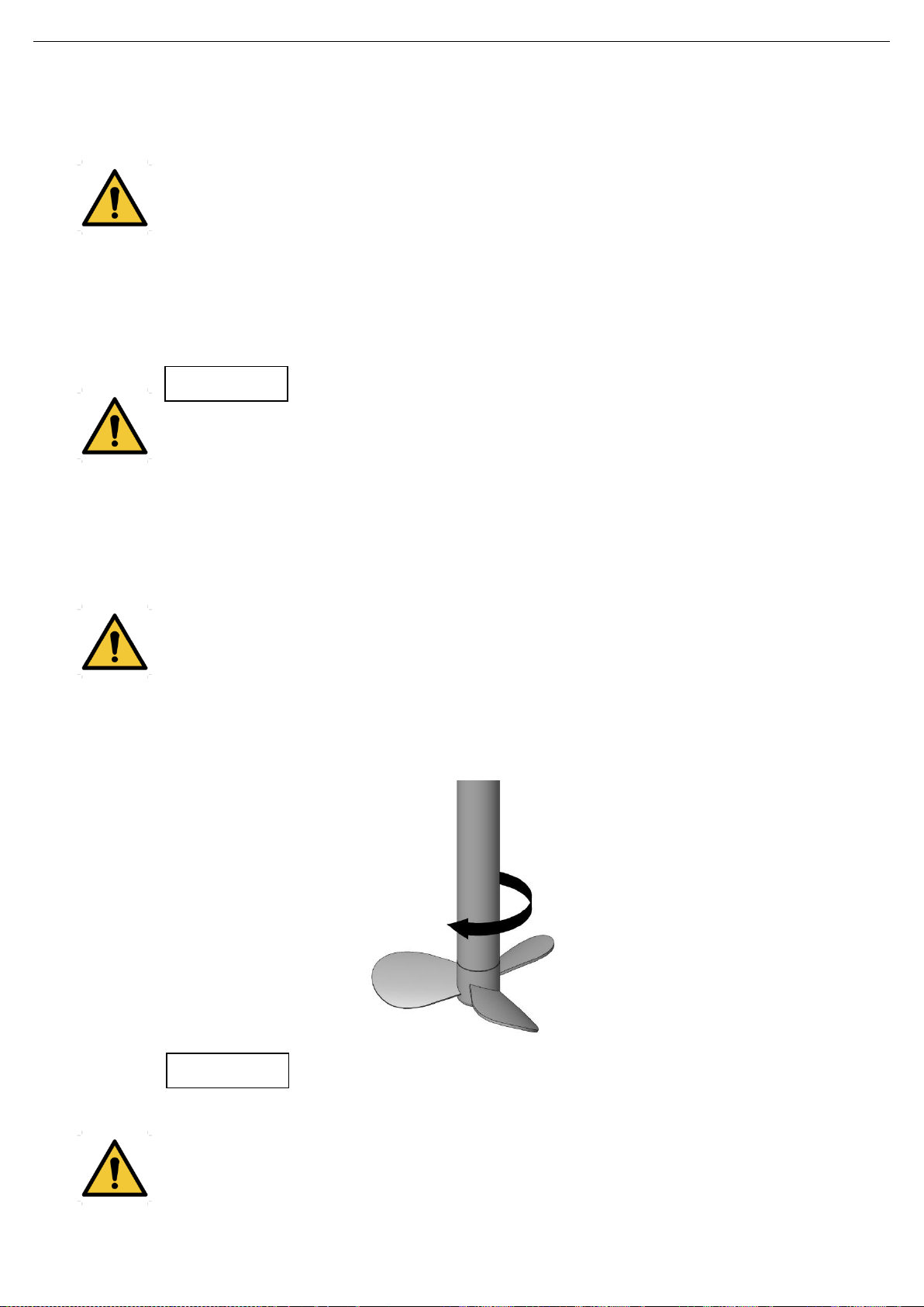
Check that the direction of rotation of the propellers is correct (it must rotate clockwise when see form the
drive side).
Follow the direction of rotation of the agitation components as indicated by the arrow attached to
the engine. An incorrect direction of rotations results in a loss of agitation performance.
Check the electrical consumption of the motor.
After a running-in period, check that the mechanical seal does not leak. If it does change it as shown in
the chapter 8.6. Disassembly and assembly agitator.
Do not modify the operating parameters for which the agitator was initially designed without written
authorisation from INOXPA (risk of damage and user hazard).
Follow the instructions for use and the safety requirements described in the instructions manual for
the tank in which the agitator is mounted.
Mechanical risk (e.g. drag, shear, cutting, impact, flattening and pinching). If the agitation element
is accessible from the top or the tank inspections hatch, then the user will be exposed to the
above-mentioned risks.
ATTENTION
ATTENTION
20.025.32.0004

Start-up
14 INOXPA S.A.U. 20.025.30.01EN · (0) 2019/04
The tank must be fitted with protective devices and safety equipment. Consult the manufacturer’s instructions
manual.
Introducing an object or solid raw material may cause the agitation component and other
mechanical parts to break and compromise its safety or guarantee.
ATTENTION
Troubleshooting
INOXPA S.A.U. 20.025.30.01EN · (0) 2019/04 15
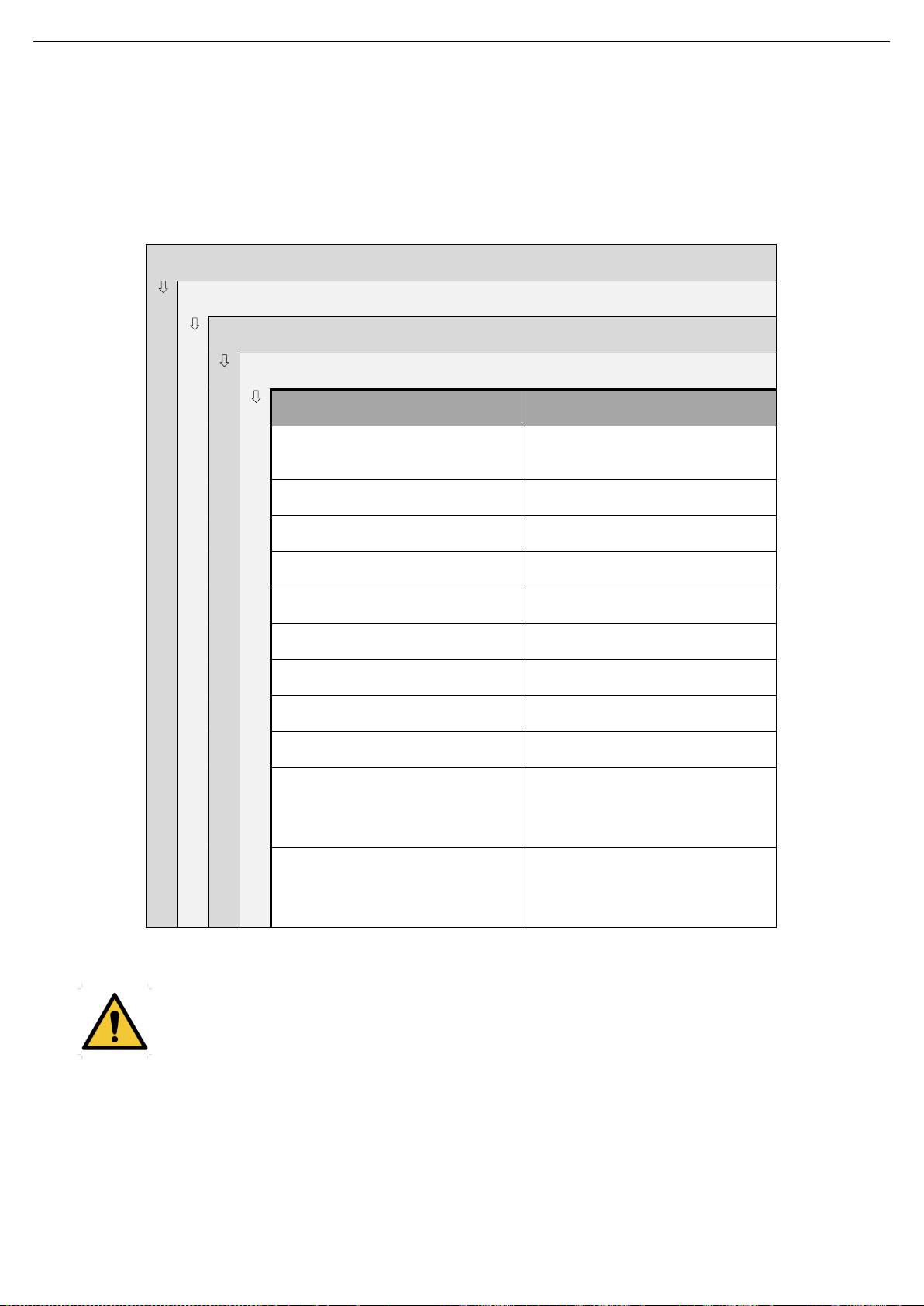
7. Troubleshooting
The attached table lists solutions to problems that may arise while operating the agitator. It is assumed that the
agitator has been properly installed and that is has been selected correctly for the specific application.
Contact INOXPA if technical assistance is required.
Motor overload
Insufficient agitation
Vibrations and noise
Leaks
PROBABLE CAUSES
SOLUTIONS
Viscosity of the liquid too high
Reduce the viscosity, e.g. by heating
the liquid
High density
Increase motor power
Tank too big for the chosen agitator
Check with the technical department
Wrong direction of rotation
Change direction of rotation
Agitator speed too low
Increase the speed
Liquid level insufficient or none
Check liquid level in the tank
Shaft bended
Replace the shaft
Critical speed
Check with the technical department
Worn bearings
Replace the bearings agitator
Lip seal worn or damaged
If the lip seal is worn, replace it.
If the lip seal is damaged, consult the
technical department.
O-rings not the right ones for the
liquid
Fit the proper O-rings, check with the
supplier
If the problems persist stop using the agitator immediately. Contact the agitator manufacturer or the
representative.

Maintenance
16 INOXPA S.A.U. 20.025.30.01EN · (0) 2019/04
8. Maintenance
8.1. GENERAL CONSIDERATIONS
This agitator, just like any other machine, requires maintenance. The instructions contained in this manual cover
the identification and replacement of spare parts. The instructions are aimed at maintenance personnel and
those responsible for the supply of spare parts.
Carefully read chapter 9. Technical Specifications.
Maintenance work can only be carried out by qualified personnel that are trained and equipped
with the necessary resources to carrying out this work.
Before beginning maintenance work, ensure that the electric motor is disconnected and that the
tank is empty.
All parts or Materials that are replaced must be properly disposed of/recycled in accordance with
the current directives applicable in each area.
Before beginning maintenance work, ensure that the agitator is disconnected.
8.2. MAINTENANCE
Inspect the agitator regularly.
Do not fail to keep the agitator clean.
Check the state of the motor or the gear motor.
Check the state of the bearings.
Check the sealing: seal and/or V-ring.
Motor or gear motor maintenance shall be carried out in accordance with the manufacturer’s instructions, see
the instructions manual.
8.3. LUBRICATION
The LR/LM side-entry agitators are supported on permanently lubricated bearings, which means maintenance is
not required. The bearings can be re-greased disassembling the support, cleaning the previous grease off the
bearings or by replacing them. The bearing houses are also cleaned and finally re-greased with a 50%-80%
grease.
When re-greasing, use only special grease for ball bearings with the following properties:
Lithium-based or made up of high quality lithium,
Viscosity 100-140 cSt at 40ºC,
Consistency NLGI grade 2 or 3,
Continuous work temperature -30ºC to 120ºC.
The lubrication of the bearings of the motor or the gear motor will be carried out according to the manufacturer’s
instructions.
8.4. SPARE PARTS
To order spare parts it is necessary to indicate the type and serial number included on the agitator’s
characteristics plate, as well as the position and description of the part as found in chapter 9. Technical
Specifications.
8.5. CONSERVATION
If the agitator is out of service for a considerable period of time, clean and treat the parts with VG46 mineral oil.
The shaft must be stored in the horizontal position and on wooden supports or on supports of a similar material.

Maintenance
INOXPA S.A.U. 20.025.30.01EN · (0) 2019/04 17
8.6. DISASSEMBLY AND ASSEMBLY OF THE AGITATOR
The disassembly and assembly of the agitators should only be carried out by qualified personnel
using only appropriate tools. Ensure that staff read these instructions manual attentively,
particularly the instructions that relate to their work.
Stop the motor from starting up when carrying out assembly and disassembly work on the agitator.
Place the agitator switch in the “off” position.
Lock out the electrical switchboard or place a warning sign.
Remove the fuses and take them to the workplace.
8.6.1. Disassembly of the agitator
Once the motor is disconnected, disassembly work may begin:
Empty the tank.
Remove the propeller (02) that is screwed to the agitator shaft (05) knocking a blade lightly with a plastic
hammer in counter-clockwise direction as seen from the front of the propeller. Take care to retain the O-
ring (80) in the agitator shaft (05).
Remove carefully the two parts of the mechanical seal (08), loosening the allen studs that hold them.
Remove shaft guards (47) together with its hexagonal screws (52B) and flats washers (53B).
Remove the hexagonal screws (52C) from the motor or gear motor and loosen the allen studs (55A) from
the bearing support (70).
Move the motor or gear motor and the agitator shaft (05) backwards, taking care not to hit or strain the
agitator shaft.
Remove the allen studs (55) that fix the shaft to the motor and separate the motor or gear motor (93) of
the agitator shaft (05).
Finally, remove the hexagonal screws (52, 52A), flat washers (53, 53A) that separate the flange (23)
from the lantern (04) and the latter from the bearing support (70).
8.6.2. Assembly of the agitator
Assemble the agitator shaft (05) onto the motor or gear motor (93). Locate the threaded holes above the
keyway. Introduce the allen studs into these holes and tighten until they lock on the keyway. The allen
studs must not protrude from the external diameter of the shaft.
Assemble the bearing support (70) in the lantern by means of the hexagonal screws (52A) and flat
washers (53A), without tightening them.
Introduce the agitator shaft and the motor through the bearing support (70) until the flange of the lantern,
and firmly tighten the hexagonal screws (52C).
Tighten the hexagonal screws (52A) of the bearing support (70).
Next, place the flange (23) on the lantern centering (04) fixing through the hexagonal screws (52) and flat
washers (53).
Check that the surfaces of the agitator shaft (05) and the flange (23) are in good condition (perfectly
polished finish).
When fitting the new seals, be sure to wet the O-rings with soapy water so that the fixed parts slide easily
into their locations and the rotating parts onto the shaft.
Place the stationary part of the mechanical seal (08) on its location on the flange (23).
Place the rotating part of the mechanical seal (08) and fix it to the agitator shaft through its fixing studs as
shown in the assembly instructions, figure 8.1.
Locate the shaft guards (47) with the hexagonal screw (52B) and flat washers (53B) to the lantern (04).
Place the O-ring (80) on the agitator shaft (05).
Install the agitator in the flange of the tank.
Finally, mount the propeller (02) firmly on the agitator shaft (05), checking that it will not become loose.
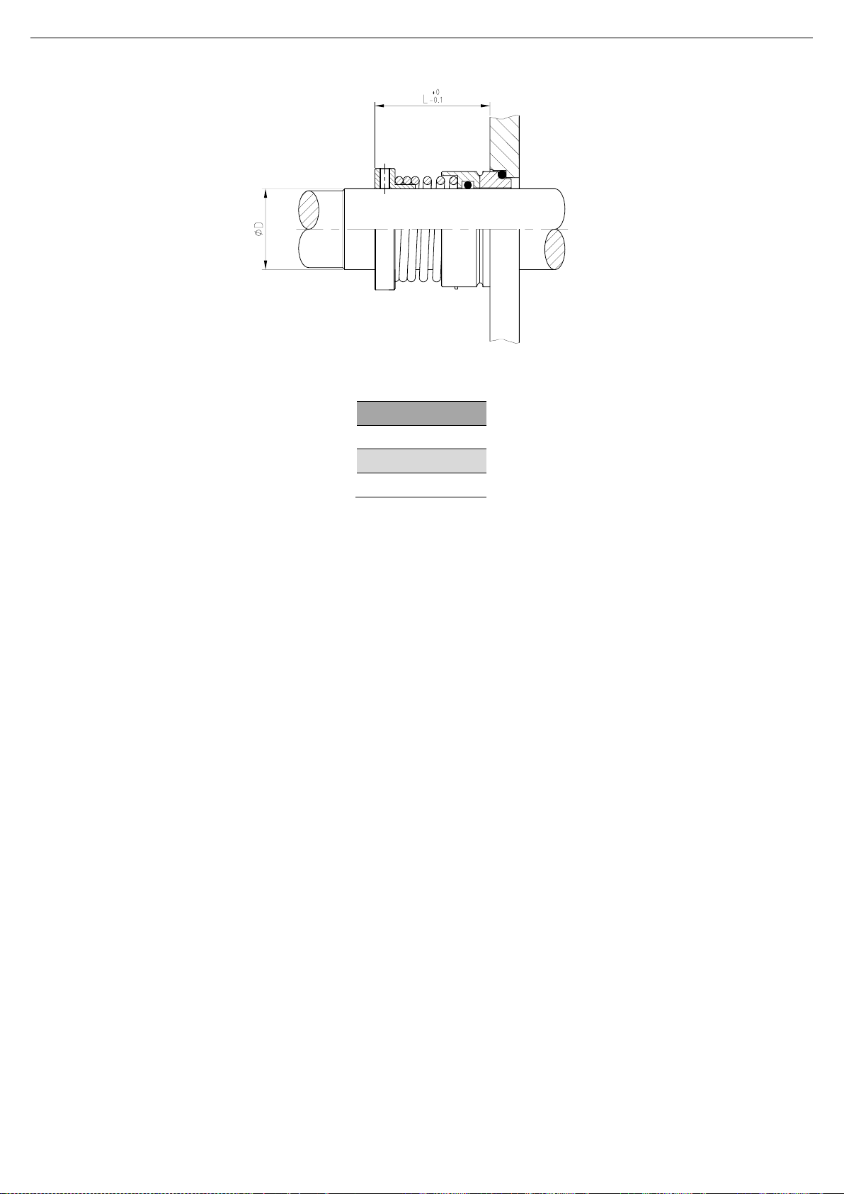
Maintenance
18 INOXPA S.A.U. 20.025.30.01EN · (0) 2019/04
ØD
L
40
47
50
51,5
60
61,5
20.025.32.0005

Technical Specifications
INOXPA S.A.U. 20.025.30.01EN · (0) 2019/04 19
9. Technical Specifications
9.1. MATERIALS
Parts in contact with the product AISI 316L
Other steel parts GG15
V-ring and retainer C/SiC/EPDM
Bearing support EPDM
Surface finish Ra ≤ 0,8 μm
9.2. OTHER FEATURES
Motor 4 poles, 3 ph, 230/400 V, 50 Hz
Speed (rpm) 1.500
Maximum motor power (kW) LR: 4 kW; LM: 11 kW
Maximum shaft length (mm) LR: 500; LM: 600
Maximum shaft diameter (mm) 60
Maximum propeller diameter (mm) LM: 350; LR: 650
Propeller Marine propeller (type 10)
9.3. WEIGHTS
Type agitator
Weigh (kg)
LR 1.10-20005-1-325
54
LR 1.10-20007-1-400
57
LR 1.10-20015-1-500
64
LR 1.10-20030-1-600
77
LR 1.10-20040-1-650
135
Type agitator
Weigh (kg)
LM 1.10-4015-1-175
46
LM 1.10-4030-1-200
56
LM 1.10-4055-1-225
66
LM 1.10-4075-1-250
75
LM 1.10-4110-1-275
145
LM 1.10-6011-1-200
48
LM 1.10-6022-1-225
62
LM 1.10-6030-1-250
66
LM 1.10-6055-1-275
75
LM 1.10-6075-1-300
150
LM 1.10-6110-1-350
182
Technical Specifications
20 INOXPA S.A.U. 20.025.30.01EN · (0) 2019/04
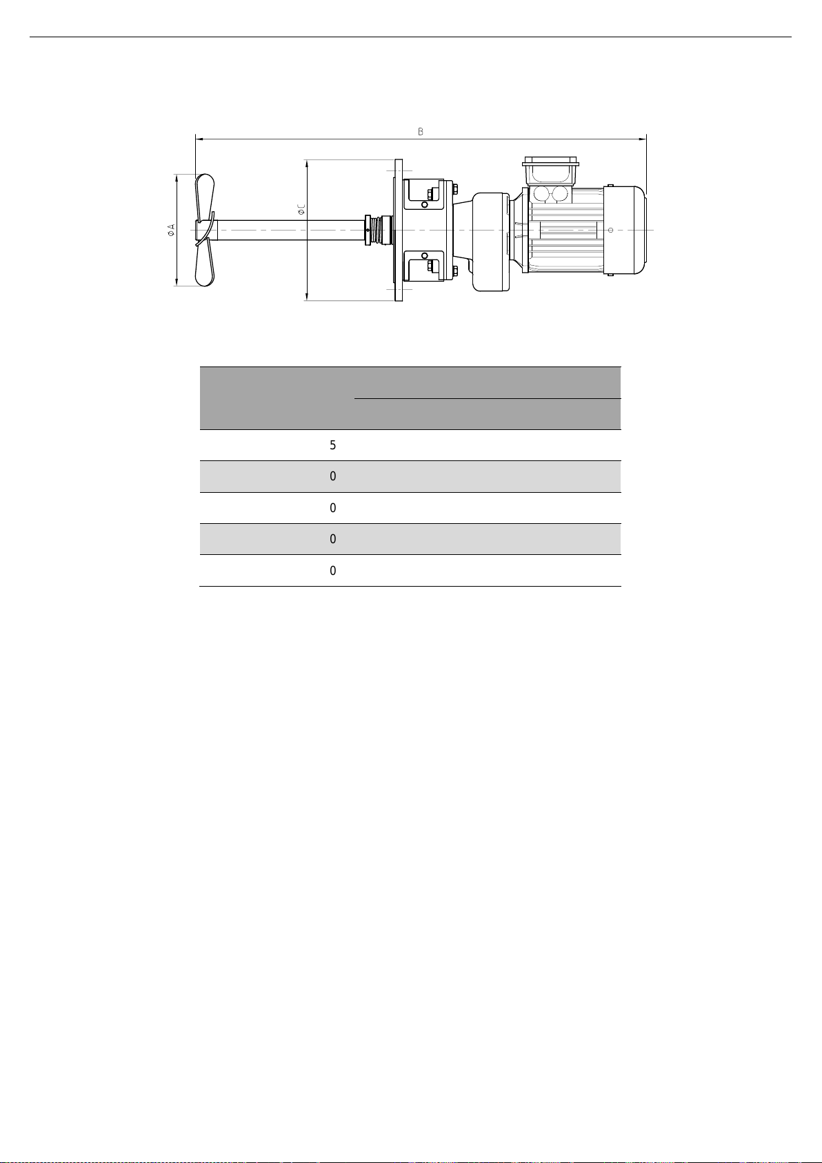
9.4. DIMENSIONS OF LR SIDE-ENTRY AGITATOR
Type agitator
Dimensions (mm)
A
B
C
LR 1.10-20005-1-325
325
910
285
LR 1.10-20007-1-400
400
910
285
LR 1.10-20015-1-500
500
950
285
LR 1.10-20030-1-600
600
1.165
340
LR 1.10-20040-1-650
650
1.205
395
20.025.32.0011
This manual suits for next models
17
Table of contents
Other INOXPA Mixer manuals


