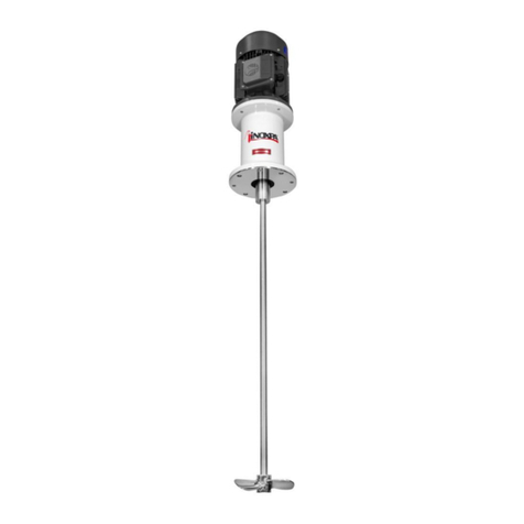
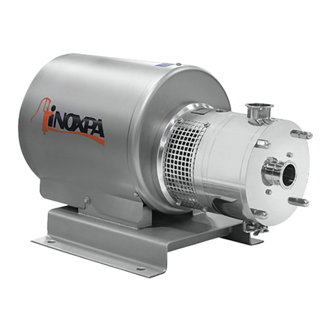
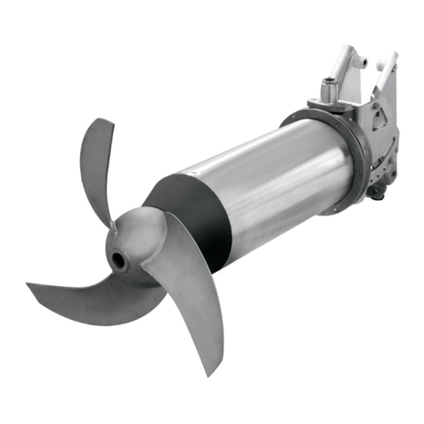
INOXPA 6100 Ex Series Manual

1
INSTALLATION, SERVICE AND MAINTENANCE
INSTRUCTIONS
ANNEX FOR EC ATEX REGISTERED EQUIPMENT UNDER DIRECTIVE
2014/34/EU:
6100 Ex serie BOTTOM MIXER
The contents of this Annex complements the information included in the
instruction manual. The instructions of this Annex must be observed
whenever equipment registered under Directive 2014/34/EU is used.
Manual Original
03.600.30.04EN
(D) 2022/04
This Annex is to be added to the manuals of the ATEX registered
components that form part of the assembly (e.g. driving, etc.).

03.600.30.07EN
(0) 2022/11
(1) Where x is a numeric character
EU Declaration of Conformity
We,
INOXPA, S.A.U.
Telers, 60
17820 –Banyoles (Girona)
Hereby declare under our sole responsibility that the machine
TANK BOTTOM MIXER
Designation
ME
Type
ME 6100
From serial number Ixxxxxxxxx to Ixxxxxxxxx (1)
Is in compliance with applicable provisions of the following directive:
Directive ATEX 2014/34/EU
Applicable harmonized standards:
EN ISO 80079-36:2016
EN ISO 80079-37:2016
EN 1127-1:2019
EN 13237:2012
EN 15198:2007
EN IEC 60079-0:2018
This Declaration of Conformity covers equipment with the following ATEX marking:
The technical documentation referenced 14771110-778370 is on file with the notified body
LABORATOIRE CENTRAL DES INDUSTRIES ELECTRIQUES (LCIE), 33, Av. du Général
Leclerc BP 8, 92266 Fontenay-aux-Roses, France. Reference num. 0081.
The person authorized to compile the technical documentation is the signer of this document.
Banyoles, 2022
II 2G Ex h IIB T4…T3 Gb
II 2D Ex h IIIB T125 ºC…T200 oC Db
II 2G Ex h IIB T4…T3 Gb
II 2D Ex h IIIB T125 ºC…T200 oC Db
David Reyero Brunet
Technical Office Manager

2
1. Safety Instructions
1.1. SAFETY INSTRUCTIONS
This Annex to the instruction manual, together with the manual, contains the basic indications which should be fulfilled during
the installation, starting and maintenance. Consequently, it is indispensable that prior to the installation, the installer as well as
the technical personnel responsible for the plant read this Annex to the instruction manual and that this remains permanently
available in the proximity of the corresponding mixer or installation.
Not only should the safety instructions indicated in this chapter be observed and fulfilled, but so should the special measures
and recommendations included in the other chapters of this manual.
1.2. SYMBOLS USED
The safety instructions contained in this Annex, whose non-fulfilment could cause a risk for persons or for the machine and its
operation, are expressed through the symbols indicated in the following:
This sign will identify all the safety instructions given in this Annex concerning the danger of the
development of explosive atmospheres as well as the creation of sources of ignition in potentially
explosive atmospheres when failure to comply with those instructions can threaten your safety.
1.3. GENERAL SAFETY INSTRUCTIONS
•Read the instructions contained in this Annex on a complementary basis with the manual
before installing the mixer and starting it.
•The installation and use of the mixer should always be in accordance with applicable
regulations in regard to health and safety.
•All the electric work should be carried out by specialised personnel.
•Control the characteristics of the motor and operation of the control board, above all in areas
where there is a risk of fire or explosion (classified zones). The responsible person of the user
company should define the risk zones (zone 0 –1 –2).
•On dismantling the mixer, the possible formation of potentially explosive atmospheres should
be considered, for which the responsible person of the user company should issue safe work
permits.
•The maximum operating conditions of the mixer should not be exceeded. Nor should the
operating parameters for which the mixer was initially designed be modified without written
authorisation from INOXPA.
•Under no circumstances should the limit values of working conditions in explosive
atmospheres be exceeded.
•Standard mixers are not designed to work during the filling or emptying of tanks. This could
cause the premature deterioration of the motor bearings, causing the temperature to rise to
unacceptable levels for the classified zone.

3
1.4. GUARANTEE
Finally, we should point out that any guarantee issued will be cancelled immediately and as a matter of law and, in addition,
we will require compensation for any claims of civil liability presented by third parties in case of non-fulfilment of any of the
indications given in the attached annex or:
The mixer was selected for working conditions in explosive atmospheres at the time the order was placed.
INOXPA will not be responsible for any damage which may be caused if the information provided by the
buyer is incomplete or incorrect (type of liquid, viscosity, RPM, classification of the potentially explosive
zone, gas generated by the potentially explosive atmosphere, etc.).
The General Delivery Terms already provided also apply.
1.5. INSTRUCTION MANUAL AND ANNEX FOR ATEX EQUIPMENT
The information published in the instruction manual and in this Annex which complements this is based on updated
information.
We reserve the right to modify the design and/or manufacture of our products when we consider it opportune, without having
any obligation to appropriately adapt any product supplied beforehand.
The technical and technological information issued in this Annex, together with the graphs and technical specifications we
provide, will continue to be our property and should not be used (unless it is used for the starting of this installation), copied,
photocopied, delivered or communicated to third parties without prior written notice.
INOXPA reserves the right to modify this Annex to the instruction manual without prior notice.

4
Table of Contents
1. Safety Instructions
1.1. Safety Instructions ......................................................................................................2
1.2. Symbols used ..............................................................................................................2
1.3. General safety instructions .........................................................................................2
1.4. Guarantee ...................................................................................................................3
1.5. Instructions Manual ....................................................................................................3
1.6. INOXPA Service ........................................................................................................3
Table of Contents
2. Receipt, storage and transport
2.1. Receipt ........................................................................................................................6
2.2. Storage ........................................................................................................................6
2.3. Transport .....................................................................................................................6
3. Identification, description and use
3.1. Identification ...............................................................................................................7
3.2. Description .................................................................................................................7
3.3. Using the mixer ..........................................................................................................7
3.4. Application ………………………………….…………………………...................……… 7
4. Installation and assembly
4.1. Installation and assembly ...........................................................................................8
4.2. Location ......................................................................................................................8
4.3. Assembly ....................................................................................................................8
4.4. Electrical Connection .................................................................................................9
5. Start-up, operation and shutdown
5.1. Start-up .......................................................................................................................10
5.2. Operation ....................................................................................................................10
6. Maintenance and storage
6.1. Maintenance ...............................................................................................................11
6.2. Lubrication .................................................................................................................11
6.3. Spare parts ..................................................................................................................11
6.4. Storage ........................................................................................................................11
7. Faults: causes and solutions
8. Assembly and disassembly
8.1. Electrical safety ..........................................................................................................13
8.2. Disassembly and assembly of mixer ...........................................................................13
8.3. Disassembly and assembly of single mechanical seal ................................................13
8.4. Disassembly and assembly of single mechanical seal with flushing ..........................14
8.5. Disassembly and assembly of double mechanical seal ...............................................14
8.6. Disassembly and assembly of shaft ...........................................................................14
9. Technical Specifications
9.1. Technical specifications and dimensions ....................................................................16
9.2. Dimensions..................................................................................................................17
9.3. Cross-section ............................................................................................................... 18
9.4. Levels of assembly ……………………………………………………………… …19
9.5. Parts list …………………………………………………………………………. ….19

5
2. Receipt, storage and transport
2.1. RECEIPT
Check the ATEX CE marking on the nameplate of the machine and verify that it meets the conditions of the order.
Figure 1.1.: ATEX CE marking on the nameplate.
Should the marking on the machine not correspond with the order, please contact INOXPA immediately to explain the
situation.
The temperature class and the maximum surface temperature depend on the temperature of the product to be stirred and the
ambient temperature.
Temperature class for explosive gas atmospheres
Temperature
class
Product temperature (in process
or cleaning)
Room temperature
T4
≤ 110 °C
-20 °C to +40 °C
T3
≤ 140 °C
-20 °C to +40 °C
Maximum surface temperature for explosive dust atmospheres
Maximum
surface
temperature
Product temperature (in process
or cleaning)
Room temperature
T125 °C
≤ 125 °C
-20 °C to +40 °C
T200 °C
≤ 200 °C
-20 °C to +40 °C
II 2G Ex h IIB T4…T3 Gb
II 2D Ex h IIIB T125ºC…T200 oC Db
II 2G Ex h IIB T4…T3 Gb
II 2D Ex h IIIB T125ºC…T200 oC Db

6
3. Identification, description and use
3.1. IDENTIFICATION
The mixer is identified by means of a nameplate. The mixer type and the serial number can be found on the plate.
In addition to the information in the manual it should be taken into account that ATEX equipment will be provided with the
corresponding marking.
3.2. DESCRIPTION
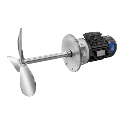
For series Ex ME-6100 mixers, the driving should be appropriate to operate in explosive atmospheres.
Mechanical seal suitable for working in classified areas. The installation instructions provided by the seal supplier must be
followed.
The mixer was selected for working conditions in explosive atmospheres at the time the order was placed.
INOXPA will not be responsible for any damage which may be caused if the information provided by the
buyer is incomplete or incorrect (type of liquid, viscosity, RPM, classification of the potentially explosive
zone, gas generated by the potentially explosive atmosphere, etc.).
Single mechanical seal. If the single mechanical seal is working in dry conditions, its maximum operating temperature may be
exceeded. This is why a simple mechanical seal must not operate under any circumstances in dry conditions.
-Regularly check that the single mechanical seal is functioning correctly.
-Check that the hydraulic part of the pump is always free of liquid during operation.
-Avoid pumping fluids that contain large amounts of gas.
The end user must ensure a liquid level above the mixer of at least a height equal to 2 times its diameter, by means of a level
detector, to avoid an increase in surface temperature due to dry working.
-Double pressurized mechanical seal option. Must be protected by controlling the washing liquid.
oCheck the level of supply reserve.
oCheck the temperature of the washing liquid.
oCheck the pressure.
oCheck the condition of the washing liquid: Change the washing liquid if it has been contaminated by
another liquid. Contamination of the liquid means that the pump is not functioning properly and it must
be inspected. For example, the sealing system may have leaks in the middle or be open due to
insufficient backpressure of the washing liquid.
Caution! The washing liquid must always be under pressure when the pump is operating.
-Cooled mechanical seal option.
•Check the level of supply reserve.
•Check the temperature of the washing liquid.
•Check the pressure.
Attention: the cleaning liquid must always be under pressure when the mixer is in operation
•Check the condition of the washing liquid by inspecting it: Change the washing liquid
if it has been contaminated by another liquid.
Frequent contamination is indicative of an unacceptable leak in the sealing system that must be repaired.

7
Contamination of the liquid means that the pump is not functioning properly and it must be inspected. For example,
the sealing system may have leaks in the middle or be open due to insufficient backpressure of the washing liquid.

8
4. Installation and assembly
4.1. INSTALLATION AND ASSEMBLY
ATEX mixers are compact units and are ALWAYS supplied together with the driving.
4.2. LOCATION
It is very important to be able to access the electric connection device of the mixer, even when in operation.
It should be considered that during any operation of the electric connection equipment there may
be a potentially explosive atmosphere, for which safe work permits should be issued.
It should be ascertained that there is air circulation for the mixer driving to cool.
Ensure that there is no other equipment or surfaces close to the driving which might radiate
additional heat or affect the cooling of the driving. See the driving's instructions manual.
If necessary, install an independent fan, taking into consideration the atmosphere in which this fan will operate (potentially
explosive atmosphere).
Excessive temperatures
Depending on the fluid to be agitated, high temperatures may be reached inside and around the mixer:
Note that the surface temperature of the mixer in normal operating conditions is determined
by the fluid it agitates. Therefore the table of temperature classes and maximum surface
temperature in section 2.1 must be taken into account.
4.4. ELECTRIC CONNECTION
Before connecting the driving to the system, consult the supplier's instruction manual. This driving should be ATEX with
adequate protection for the work environment in which it operates.
Before connecting an electric driving to the system, check local regulations regarding electric safety, as well as standards EN
60204-1 and EN 60079-14 currents of the moment.
The electrical equipment, terminals and components of the control systems may still contain
electric current when switched off. Contact may place the operator or installation in danger or
cause irreparable damage to the material. The supplier's instructions for the safe opening of the
driving should be followed at all times.
Safe work permits should be issued for any handling of equipment in potentially explosive
atmospheres, with it being advised to carry out this type of work in unclassified atmospheres (there
should not be an explosive atmosphere where the mixer is located during handling).
Follow the driving manufacturer's indications at all times.

9
The control equipment should comply with the regulations in effect, as is stipulated by the electric
safety standard, as well as the indications established by the ATEX driving manufacturer.
Also install protection against driving overload suitable to the nominal driving instructions manual.

10
5. Start-up, operation and shutdown
5.1. START-UP
Explosive atmospheres may be generated during the start-up of the mixer, for which safe work
permits should be issued and this work should only be carried out by qualified or trained personnel.
The work without product can generate a temperature in the mechanical seal superior of the allowed
in the classified zone.
5.2. OPERATION
Do not modify the operating parameters for which the mixer was selected; deterioration
may be produced, which is dangerous for the user and there is a risk of forming explosive
atmospheres and the creation of sources of ignition.
The mixer cannot be operated without liquid. A safety system is therefore required to ensure a minimum liquid level
from at least a height to 2 times his diameter, when the mixer is operational.

11
6. Maintenance and storage
Maintenance work on any equipment intended for use in potentially explosive atmospheres should
involve the adoption of safe work permits as stipulated by Directive 1999/92/CE.
6.1. MAINTENANCE
The possible presence of explosive atmospheres or the formation of these during the maintenance
work should be considered, for which safe work permits should be issued.
The maintenance of the driving and mechanical seal shall be carried out according to the
manufacturer's indications (See instruction manual).
Use technically adequate tools for the maintenance and repair work. In case the zone is not
declassified, all the tools should be non-sparking and safe work permits should be issued.
In the case of painting the parts of the mixer (except driving), the type of paint to be used must be
conductive, dissipative or antistatic insulating, so that no accumulation of charges occurs or, if yes,
these are controlled (paint must have a surface resistivity < or = 1 Gohm).
6.3. SPARE PARTS
On requesting the spare parts of a mixer to operate in a classified zone, the order should explicitly indicate that these are
for ATEX mixer and indicate the manufacturing number.
In case of failing to do so, INOXPA will not be responsible for the mixer operating with parts which are inadequate for the
classified zone where installed.

12
8. Assembly and disassembly
The assembly and disassembly work of any equipment to be used in potentially explosive atmospheres
should involve the adoption of safe work permits, in accordance with that specified by Directive
1999/92/CE.
Both assembly and disassembly of the mixers should be carried out by qualified personnel, using only
appropriate tools, as well as adequate work methods.
Use technically adequate tools for the maintenance and repair work. In case the zone is not
declassified, all the tools should be non-sparking and safe work permits should be issued.
An incorrect assembly or disassembly may cause damage in the operation of the mixer, resulting in
high repair costs, an extensive period of inoperation and even invalidate the protection systems of the
equipment.
INOXPA is not responsible for accidents or damage caused as a result of the non-fulfilment of the
instruction manual and this Annex.
Cleaning
Before proceeding with the disassembly of the mixer it is necessary to clean it, on the inside as well as outside. In addition, the
possible presence or formation of explosive atmospheres should be considered; consequently, safe work permits should be
issued.

13
9. Technical Specifications
Temperature range. See section 2.1.
Table of contents
Other INOXPA Mixer manuals
Popular Mixer manuals by other brands

Imetec
Imetec G4301 operating instructions
BeON
BeON BN-2206 instruction manual

Evolution
Evolution TWISTER Original instructions
Gastroback
Gastroback Design Mixer Advanced Electronic Operation instructions

Living & Co
Living & Co LSM250W instruction manual

Winget
Winget Crocker RP1500XD Parts & operation manual
