The Handy THLCHCM Installation and operation manual

OPERATOR’S MANUAL & PARTSLIST
MODEL –THLCHCM
H-FRAME ELECTRIC CEMENT MIXER
Spares & Support: 01793 333212
Please read & understand this manual, paying particular attention to the safety
instructions, before use.
The manufacturer reserves the right to change the product specification and
livery according to continued product improvements.
193821002 08/07/2015


CONTENTS
SPECIFICATIONS
SAFETY INSTRUCTIONS
OPERATING INSTRUCTIONS
MAINTENANCE & STORAGE
ASSEMBLY
PARTS DIAGRAM & LIST
GUARANTEE
NOTES

SPECIFICATIONS
Model
THLCHCM
Product Number
193821002
Motor Power
550 watt
Drum Diameter
570mm
Drum Opening
385mm
Drum Capacity
125 litre
Maximum Mixing Capacity
90 litre
Drum Speed
26.6rpm
Cable Length
1.7 metre
Protective System
IP45D
Overall Dimensions
(L)1200mm–(W)710mm –(H)1400mm
Unladen Weight
48kgs
Noise Level
90 dB(A)
The manufacturer reserves the right to change the product specification and livery according to
continued product improvements.

GENERAL SAFETY INSTRUCTIONS
Read and understand the owner’s manual and labels affixed to the machine. Learn its application
and limitations as well as the specific potential hazards. Retain these instructions for future
reference. The operator is responsible for following the warnings & instructions in this manual and
on the product.
Read & understand operator’s manual
before using the machine. Failure to
follow instructions could result in
death or serious injury.
Always inspect the machine thoroughly
before turning it on. Keep guards in place
and in working order. Do not use the
machine with the electric motor cover
removed.
Wear gloves to protect your hands
Do not start the motor if the drum is fully
loaded. Do not turn the mixer off while full
of concrete.
Whenever the machine is in use, safety
glasses must be worn to safeguard
against flying objects.
Only use or operate the mixer on solid, flat,
level ground that is capable to support the
weight of the mixer and its load to prevent
the mixer from tipping over.
Do not attempt to move the mixer when it
is loaded and/or in operation.
Wear foot protection
Fire Risk
Fire and its vapors are extremely flammable
& explosive.
Fire or explosion can cause severe burns or
death.
Keep hands out of the way of all
moving parts. Do not place any part of
your body or any tool e.g. Shovel in the
drum during operation. When
operating, do not pass hands through
the clearance between frame and
support arm or between the drum and
support arm.
Disconnect from power supply when not in
use, before moving, making adjustments,
changing parts, cleaning, or working on the
mixer. Never open the motor cover before
disconnecting the electrical plug from the
power supply.
Double insulated or class 2 electrical
appliances are products that have been
designed in a way so as not to require a
safety connection to electrical earth
(These products must NOT have a
safety connection to Earth).
10m
Keep all bystanders & animals at least
10 metres away from the machine
during operation.
If approached, stop the machine
immediately.
Acoustic power level LWA accordance with
directive 2000/14/EC + 2005/88/EC
(Please see machine & specification within
this manual for actual reading)

STAY ALERT
Do not operate the mixer while under the influence of drugs, alcohol, or any medication that could affect your
ability to use it properly. Do not use this mixer when you are tired or distracted from the job at hand. Be aware
of what you are doing at all times. Use common sense.
AVOID DANGEROUS CONDITIONS
Make sure there is adequate surrounding workspace. Cluttered areas invite injuries.
Keep your work area clean with sufficient light. Keep area around the mixer clear of obstructions, grease, oil,
rubbish and other debris which could cause persons to fall onto moving parts.
This mixer is intended for the production of concrete, mortar and plaster. It is not suitable for the mixing of
flammable or explosive substances. Do not use it in areas where fumes from paint, solvents or flammable
liquids pose a potential hazard.
INSPECT YOUR MACHINE
Check all bolts, nuts, and screws for tightness before each use, especially those securing guards and drive
mechanisms. Vibration during mixing may cause these to loosen.
Form a habit of checking to see that all the adjusting tools, shovels, hand trowels and other tools/equipment
are removed from mixer area before turning it on.
Replace damaged, missing or failed parts before using it. Warning labels carry important information. Replace
any missing or damaged warning labels.
DRESS PROPERLY
Do not wear loose clothing, gloves, scarfs, neckties or jewelry (rings, wrist watches), which can be caught in
moving parts. Protective electrically non-conductive gloves and non-skid footwear are hignly recommended
when working. Wear a face or dust mask if the operation is dusty. Always wear safety glasses/goggles and/or
face shields. Everyday eyeglasses have only impact resistant lenses; they are not safety glasses/goggles. Wear
protective hair covering to contain long hair, preventing it from getting caught in machinery.
DO NOT ABUSE CORD
Never carry the mixer by the electrical cord or yank it to disconnect the plug from the mains supply.
Keep the cord from heat, oil and sharp edges.
EXTENSION CABLES
Extension cables must be no longer than 50 metres in length. The cable section must be 1.5mm² & 230V to
allow sufficient current flow to the motor. Improper use of extension cables may cause inefficient operation of
the mixer, which can result in overheating and motor damage.
Only extension cords to H07RN-F specification intended for outdoor purpose may be used. Avoid use of free
and inadequately insulated connections. Connections must be made with protected material suitable for
outdoor use. Make sure that any extension cable connections are dry and safe. Ensure that the extension cable
is carefully laid out avoiding liquids, sharp edges and places where vehicles might run over it. Avoid allowing
the extension cable to be trapped underneath the mixer. Ensure your extension cable is fully extended to
prevent overheating or the risk of fire.
AVOID ELECTRICAL SHOCK
Check the electric circuit is adequately protected and that it corresponds with the power, voltage and
frequency of the machines motor. Do not plug or unplug the motor while standing in or around damp or wet
ground. Do not use the mixer in wet or damp areas or expose it to rain. Prevent body contact with grounded
surfaces: pipes, radiators, ranges, and refrigerator enclosures.
Make sure your fingers do not touch the plug’s metal prongs when plugging or unplugging the mixer.
KEEP BYSTANDERS AND CHILDREN AWAY
Keep unauthorised persons a minimum distance of 10 metres away from the mixer. Do not allow children to
handle, climb on or in the mixer.
DO NOT OVERREACH
Keep proper footing and balance at all times when loading or unloading the mixer. Never stand on the mixer.
Serious injury could occur if the mixer is tipped or if the moving parts are unintentionally contacted. Do not
store anything above or near the mixer where anyone might stand on the mixer to reach them.

AVOID INJURY FROM UNEXPECTED ACCIDENT
Keep hands out of the way of all moving parts. Do not place any part of your body or any tool e.g. Shovel in
the drum during operation. When operating, do not pass hands through the clearance between frame and
support arm or between the drum and support arm.
DO NOT FORCE TOOL
Always work within the rated capacity. Do not use the mixer for a purpose for which it was not intended.
The mixer is not to be towed by any vehicle.
NEVER LEAVE MIXER RUNNING UNATTENDED
Do not leave the mixer unattended until it has come to a complete stop.
MAINTAIN YOUR MIXER WITH CARE
Clean the mixer immediately after use. Keep the mixer clean to ensure it operates to it’s full and safest
performance. When maintaining this mixer, only the manufacturer’s original replacement parts should be used.
The use of non-original manufacturer parts may invalidate your warranty.
PROTECT THE ENVIRONMENT
Take left over materials to an authorised collection point or follow the stipulations in the country where the
mixer is used. Do not discharge into drains, soil or water.
STORE IDLE EQUIPMENT
When not in use, the mixer should be stored in a dry location. Keep the mixer away from children and others
not qualified to use it.
Safety alert symbol. Used to alert you to potential personal injury hazards. Obey all safety messages that
follow this symbol to avoid possible injury.
DANGER
Indicates an imminently hazardous situation which, if not avoided, will result in serious injury.
WARNING
Indicates a potentially hazardous situation which, if not avoided, could result in serious injury
CAUTION
Indicates a potentially hazardous situation which, if not avoided, may result in minor or moderate injury.
CAUTION
Used without the safety alert symbol indicates a potentially hazardous situation which, if not avoided, may
result in property damage.
ELECTRICAL CONNECTION
Do not connect either core to the earth pin
This mixer is double insulated to Class II protection and IP45D rated. The insulation willonly remain
effective if the original insulating parts are used for repairs and the spaces between the original
insulation are maintained.
Double insulationeliminates the need for a three-wire grounded power cord and grounded
power supply system. Double insulated tools can use either a two or three wire extension cable.
The use of a Residual Current Device (“RCD”), on 230V electrics is recommended. If using an
extension cable, plug it directly into the RCD.
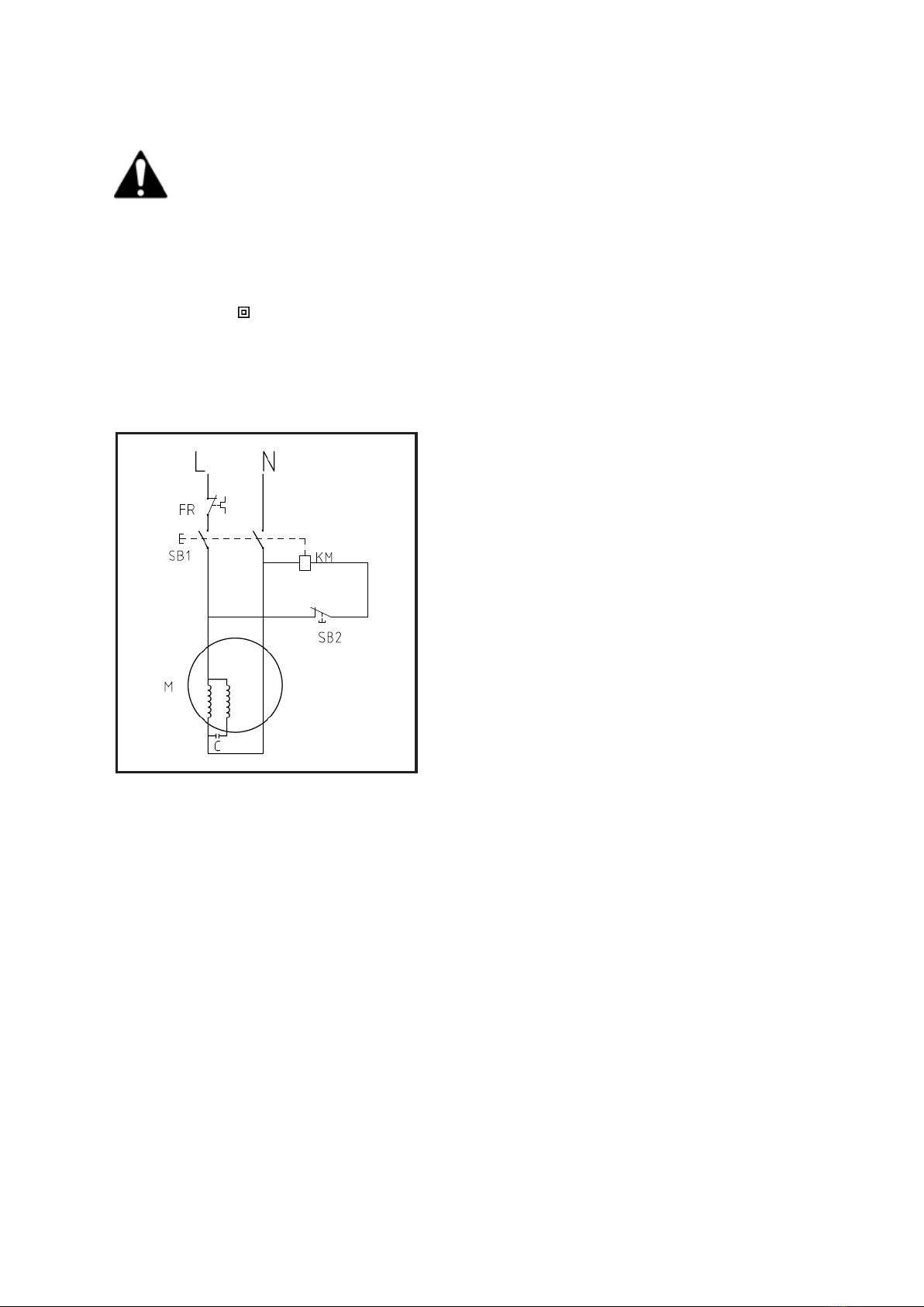
WIRING DIAGRAM
NOTE: A built-in thermal protector is arranged in the motor to prevent it from overheating. The
thermal protector restores automatically when the motor cools down.

MAINTENANCE & STORAGE
WARNING
Improper maintenance & storage of the machine may void your warranty. Keep the machine clean
for better and safer performance.
MAINTENANCE
Before each use, check all nuts & bolts to be sure they are sufficiently tightened.
The drive belt is under constant even tension by a spring loaded jockey. No adjustment apart
from a touch of grease on the spindle.
The bearings are sealed for life.
We recommend only manufacturer original parts are used when maintaining this machine.
Failure to do so could invalidate your manufacturer’s warranty.
CAUTION
Any maintenance and repairs carried out, to any electronic component must be undertaken by a
qualified technician.
CLEANING
Thoroughly clean the mixer at the end of each day’s operation.
Keep your mixer clean.
The slightest trace of material left in the drum will harden and will attract more material each
time you use it.
Dried cement should be scraped out of the drum.
Do not throw bricks into mixer drum to clean it out.
Do not beat on the drum with a shovel, a hammer or other tools to break up accumulations of
dried cement mix, as it may result in damage to the mixer.
The drum may be scoured for approximate 2 minutes, using 1” gravel and water mixture. Then
discharge the gravel/water mixture and hose down the drum assembly inside and out.
The IP45D protection class construction of the concrete mixer enables you to hose down the
drum assembly safely.
Never put hands inside the drum when the drum is rotating
WARNING
Do not pour or spray water directly over the motor cover, especially the openings in it.
CAUTION
Wipe off any external material on the motor cover. Do not use petrol, turpentine, lacquer or paint
thinner, dry cleaning fluids or similar products. The use of chemical products or solvents may affect
the properties of the cover which has been produced using high density polyethylene PET.
STORAGE
For years of trouble free service, make sure the Mixer is clean and dry beforestoring.
Before storing, clean the Mixer thoroughly as indicated above.
Store indoors or in a protected area during severe weather and winter months.

COMPONENTS

ASSEMBLY
It is recommended that The H-Frame Cement Mixer is assembled by two persons.
Remove the Mixer and contents from the carton. Be sure the carton is empty before discarding.
If you require any assistance with regards to the contents of the Mixer, please contact us:
Tel: 01793 333212 - Mon –Fri 8.00am –5.30pm (excl. Bank Holidays)
Email: customerservice@handydistribution.co.uk
STEP 1 –THE STAND
A- With a split pin inserted into the inner holes in each stub axle, place a flat washer, then a wheel
followed by another flat washer. Insert another split pin into the axle holes outside each flat washer.
Bend each side of the pins outward so they do not fall out.
B- With the frame lying on its side, attach the support leg as shown. Insert two M8X70 hex bolts
through the holes from one side, followed by flat washers, lock washers and nuts from the other
side. Tighten fully.
C -Turn the frame over and attach the axle bracket with wheel frame in the same manner.
Make sure all bolts and nuts are tightened.
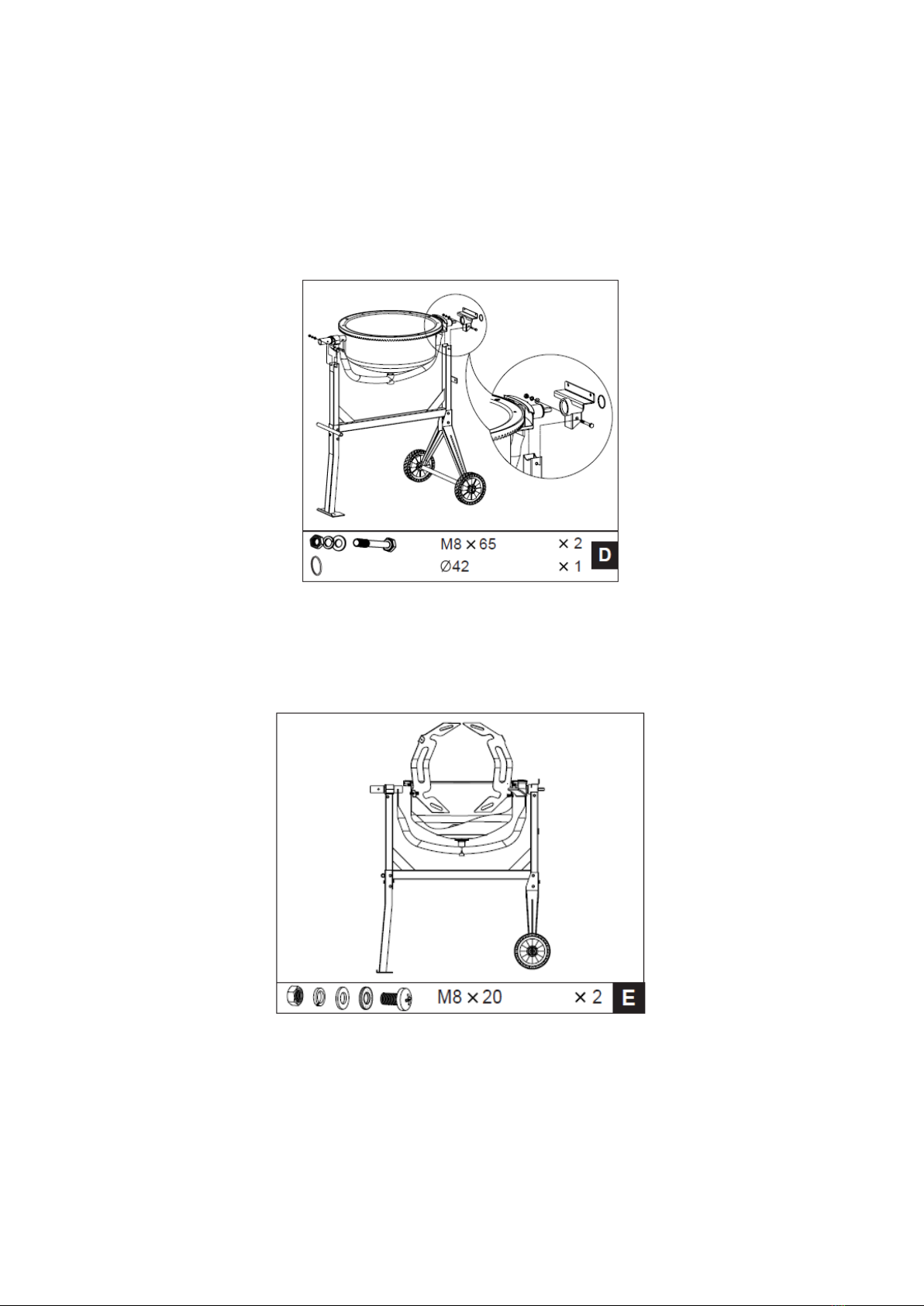
STEP 2 –THE BOTTOM DRUM
D- Slide the bearing block on the shaft. Hold it in place with Ø42 spiral ring.
Carefully, and with two people, set the bottom drum with support arm onto the side supports of the
stand as shown, so that the bearing blocks slot into the channels provided by the side supports. The
larger diameter shaft should be at the leg end of the stand.
At each side, line up the holes in the side support with those in the bearing block and insert a M8x65
hex bolt from one side, then a flat washer, lock washer and nut from the other side. Tighten with a
M8 spanner.
STEP 3 –THE MIXING BLADES
E- Mount the mixing blades inside the bottom drum loosely as shown - Two holes are provided at
the base of the drum into which a M8X20 bolt may be inserted from the outside. A rubber washer,
flat washer, lock washer and nut should be threaded on loosely on the inside. The rubber washer
should be placed under the blade down against the drum.
NOTE: Two arrow labels are affixed on the upper drum and bottom drum to assist you in lining them
up to one another. If you have any difficulty in correctly positioning the mixing blades, it is helpful if
you temporarily mount the upper drum on the top of the bottom drum, rotating it so that the two
arrows line up.

STEP 4 –THE UPPER DRUM
F- Position the upper drum onto the bottom drum over the rim, making sure the mounting holes
align in both as well as the labeled arrows.
Screw a M8x16 hex bolt with lock and flat washers into each threaded hole in the rim/ring gear.
Make sure the tightening process is carried out progressively.
Secure the mixing blades to the upper drum by inserting two M8x20 cross headed screws, from the
outside through the holes in the drum.
A rubber washer should be positioned inside between the drum and blade. Secure the mixing blade
on the inside using a flat washer, spring washer and nut.
Finally, ensure top and bottom mixing blade mountings are tight.
STEP 5 –THE TIPPING WHEEL
G- Slide the locking plate over the large diameter shaft at the leg end of the frame with the rim
facing inwards as shown. Secure with two M8x25 bolts, each with a nut, lock and flat washers.
H- Insert the spring with the washer on the top into the sleeve on the tipping wheel. Slide the wheel
over the larger diameter shaft until the holes in the bracket line up with the hole drilled. Insert a
M10X65 hex bolt with a flat washer and screw on a nut with a flat washer from the other side. Screw
the nut up against the bracket firmly, but not so tightly so as to prevent the wheel from pivoting
about the bolt. Screw a M10x40 socket head cap screw on the sleeve to adjust the spring tension
NOTE - The wheel must be allowed to pivot about the bolt, so that the lugs on the bracket can be
engaged or disengaged from the slots in the locking plate.
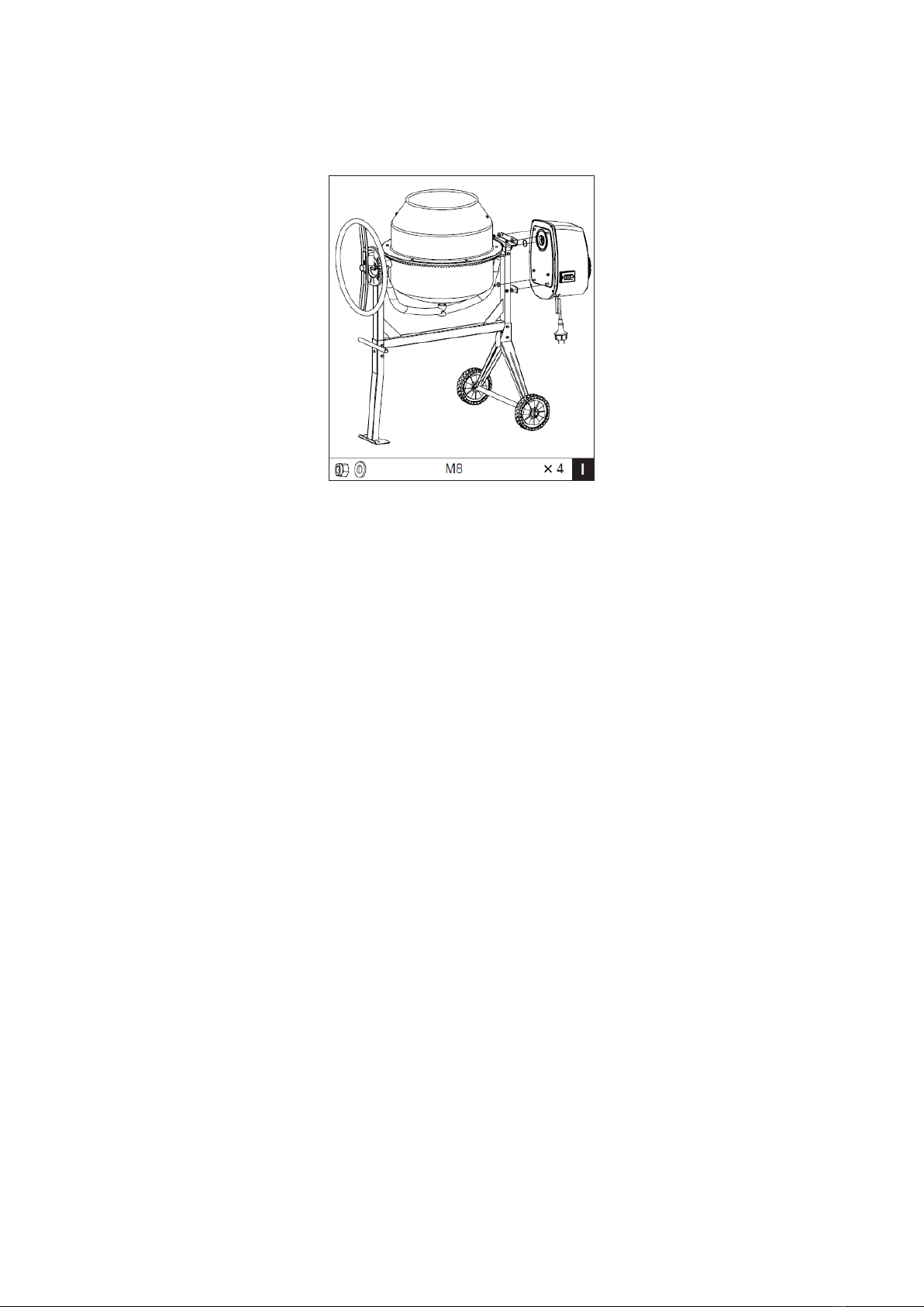
STEP 6 –THE TRANSMISSION
I - Lining up the keyways, slide the transmission case over the pinion shaft. Secure the case to
the frame with washer & M8 nut.

OPERATION
Before operating the machine, please ensure you are fully aware of the below instructions,
failure to do so, could invalidate your manufacturer’s warranty.
Completely unwind any extension cable. Connect it to the mixer first, before plugging into the
power supply.
Always start the mixer before loading the drum.
Load the drum with drum rotating.
Do not throw material into the mixer, to avoid it sticking firmly to the back of the drum.
Trickle it in steadily over the ram.
DRUM TILTING
The spring-loaded tipping wheel with locking lugs provides an easy positive control of the drum
which can be locked in the mix, discharge and stored position.
The drum is locked in position by lugs on the self-locating tipping wheel, which engages into the
locking plate on the mixer frame. To tilt the drum, withdraw the tipping wheel to dis-engage the
locking lugs. This then allows the tipping wheel and drum to be turned in the same direction.
To retain the drum in position, aligning the lugs with the slots, release the tipping wheel a little,
while retaining the drum. Rotate the tipping wheel until the locking lugs engage into the locking
plate on the mixer frame.

DRUM LOADING
For best results, proceed as follows:
Add the required amount of gravel into the drum.
Add the required amount of cement into the drum.
Add the required amount of sand into the drum.
Pour the required amount of water into the drum.
DRUM EMPTYING
Empty the drum with the drum rotating
Do not turn off the mixer with material in the drum.
MIXING HINTS
The correct mix ratio (cement: sand: stone) depends on the type of application; harder concrete
will require a higher content of cement, whilst rougher applications require more aggregate.
First put water into the drum –around 7 litres (1.5 gallons), using more or less depending on the
type of mix required. Add some aggregate before cement to avoid sticking.
The approximate mixing time for concrete is 2-4 minutes from when all the material (including
water) has been added.
Over mixing can reduce strength and cause segregation of the coarser materials.
A concrete mix which is too wet can reduce in strength and make it less able to withstand
weathering.
Never throw material into the drum, trickle it in steadily over the rim to prevent your mix firmly
sticking to the back of the drum and can only be dislodged by stopping the mixer.

PARTS DIAGRAM


PARTS LIST
Item No
Handy Part No.
Description
Qty
Item
No
Handy Part No.
Description
Qty
1
TH207-HCM450-1
Screw M8*20
4
42
TH207-HCM450-42
Circlip 62
3
2
TH207-HCM450-2
Waterproof Washer
4
43
TH207-HCM450-43
Circlip 30
1
3
TH207-HCM450-3
Flat washer 8
22
44
TH207-HCM450-44
Bearing 6206
2
4
TH207-HCM450-4
Spring Washer 8
18
45
TH207-HCM450-45
Drive Pinion
1
5
TH207-HCM450-5
Nut M8
12
46
TH207-HCM450-46
Lock Pin 6*45
1
6
TH207-HCM450-6
Mixing Blade
2
47
TH207-HCM450-47
Sleeve
1
7
TH207-HCM450-7
Lower Drum
1
48
TH207-HCM450-48
Drive Shaft
1
8
TH207-HCM450-8
Big Cogwheel
1
49
TH207-HCM450-49
Bearing 6202
2
9
TH207-HCM450-9
Upper Drum
1
50
TH207-HCM450-50
Circlip 15
1
10
TH207-HCM450-10
Bolt M8*16
6
51
TH207-HCM450-51
Circlip 42
1
11
TH207-HCM450-11
Rubber Gasket
1
52
TH207-HCM450-52
Lock Nut M8
4
12
TH207-HCM450-12
Bolt M8*12
3
53
TH207-HCM450-53
Power Cord
1
13
TH207-HCM450-13
Circlip 42
1
54
TH207-HCM450-54
Strain Relief Nut
1
14
TH207-HCM450-14
Bolt M8*70
4
55
TH207-HCM450-55
Strain Relief Rubber
1
15
TH207-HCM450-15
Axle Frame
1
56
TH207-HCM450-56
Strain Relief Bolt
1
16
TH207-HCM450-16
Wheel
2
57
TH207-HCM450-57
Strain Relief Nut
1
17
TH207-HCM450-17
Flat washer 27
4
58
TH207-HCM450-58
Switch Gasket
1
18
TH207-HCM450-18
Split Pin 5*40
4
59
TH207-HCM450-59
Screw ST3.5x16
2
19
TH207-HCM450-19
Support Arm
1
60
TH207-HCM450-60
Switch
1
20
TH207-HCM450-20
Frame
1
61
TH207-HCM450-61
Motor Cover
1
21
TH207-HCM450-21
Support Leg
1
62
TH207-HCM450-62
Motor
1
22
TH207-HCM450-22
Circlip 38
2
63
TH207-HCM450-63
Idle Pulley
1
23
TH207-HCM450-23
Left Bearing Block
1
64
TH207-HCM450-64
Belt
1
24
TH207-HCM450-24
Locking Plate
1
65
TH207-HCM450-65
Bearing 61906
2
25
TH207-HCM450-25
Bolt M8*25
2
66
TH207-HCM450-66
Snap Washer - Hole 47
1
26
TH207-HCM450-26
Bolt M8*65
1
67
TH207-HCM450-67
Screw ST4.2*16
6
27
TH207-HCM450-27
Spring
1
68
TH207-HCM450-68
Circlip 30
1
28
TH207-HCM450-28
Tipping Wheel
1
69
TH207-HCM450-69
End Plate
1
29
TH207-HCM450-29
Flat Washer 10
2
70
TH207-HCM450-70
Bolt M8*25
3
31
TH207-HCM450-31
Nut M10
1
71
TH207-HCM450-71
Motor Bracket End Plate
1
32
TH207-HCM450-32
Washer 8
1
72
TH207-HCM450-72
Gasket
1
33
TH207-HCM450-33
Bolt M10*30
1
73
TH207-HCM450-73
Bolt M8*30
2
34
TH207-HCM450-34
O-ring
1
74
TH207-HCM450-74
Oil Seal
1
35
TH207-HCM450-35
Bolt M8x65
2
75
TH207-HCM450-75
Fixed Shaft
1
36
TH207-HCM450-36
Right Bearing Block
1
76
TH207-HCM450-76
Washer
1
37
TH207-HCM450-37
Bolt 4.2*12
3
77
TH207-HCM450-77
Spring Washer 12
1
38
TH207-HCM450-38
Gear Guard 1
1
78
TH207-HCM450-78
Bolt M12*25
1
39
TH207-HCM450-39
Gear Guard 2
1

GJ HANDY & CO LTD USER WARRANTY POLICY
1. Users Statement of Warranty
Each new machine is warranted against defective material or assembly of material under normal
usage. The warranty applies to the original purchaser and covers faulty parts and the labour involved
in replacing and repairing those parts, which are of original manufacture.
2. Period of Warranty
All Webb, Handy Pro (Brushcutter & Long Handle Hedgecutter only) and Sanli domestic products
2 years from the original date of sale to the first domestic user.
90 days from the original date of sale to the professional/commercial user.
90 days from the original date of sale when used for hire.
Engines as per the manufacturer’s warranty statement which will be supplied with the machine.
1 year from the original date of purchase for Replacement Spare Parts (unless normal wear & tear
component, which are covered for 90 days).
All machines’ must be serviced within the first 12 months from the original date of purchase to
comply with the warranty, failure to do so will invalidate the 2nd year of the warranty.
A reduced warranty period of ninety days applies to those items which are subject to normal wear
and tear (e.g. wheels, tyres, cutter bars, cylinders, bottom blades, belts, cables, grass bags, spark
plugs).
All Handy, Handy Pro (All others), Mowerland and Q-Garden domestic products
1 year from the original date of sale to the first domestic user.
90 days from the original date of sale to the professional/commercial user.
90 days from the original date of sale when used for hire.
Engines as per the manufacturer’s warranty statement which will be supplied with the machine.
1 year from the original date of purchase for Replacement Spare Parts (unless normal wear & tear
component, which are covered for 90 days).
A reduced warranty period of ninety days applies to those items which are subject to normal wear
and tear (e.g. wheels, tyres, cutter bars, cylinders, bottom blades, belts, cables, collection bags,
spark plugs).
All warranty repairs must be undertaken by an authorised service dealer.
These dealers have been accredited by GJ Handy & Co Ltd and agree to only use genuine parts and
follow our repair procedures.
Version 2 06-15
This manual suits for next models
1


