INOXPA ME-1100 Manual

VERTICAL MIXER
ME-1100
Original Instructions
03.100.30.04EN
(0) 2021/05
INSTALLATION, SERVICE AND MAINTENANCE INSTRUCTIONS
03.100.32.0011

E C D e c l a r a t i o n o f C o n f o r m i t y
INOXPA S.A.U.
Telers, 60
17820 - Banyoles (Spain)
hereby declare under our sole responsibility tha the
Model: ME-1100
Technical Oce Manager
6th May 2021
03.100.30.05EN
(0) 2021/05
Document:
Revision:
Machine: VERTICAL MIXER
David Reyero Brunet
fullls all the relevant provisions of the following directive:
Machinery Directive 2006/42/EC
Regulation (EC) nº 1935/2004
Regulation (EC) nº 2023/2006
and with the following harmonized standards and/or regulations:
EN ISO 12100:2010
EN 60204-1:2018
The technical le has been prepared by the signer of this document.
1) the serial number may be preceded by a slash and by one or two alphanumeric characters
Serial number: IXXXXXX to IXXXXXX1
XXXXXXXXXIIN to XXXXXXXXXIIN1
Type: ME-1101, ME-1103, ME-1105, ME-1110, ME-1125,
ME-1130

1. Table of Contents
1. Table of Contents
2. Generalities
2.1. Instructions manual.................................................................................................................................4
2.2. Compliance with the instructions ............................................................................................................4
2.3. Warranty..................................................................................................................................................4
3. Safety
3.1. Warning symbols.....................................................................................................................................5
3.2. General safety instructions .....................................................................................................................5
4. General Information
4.1. Description ..............................................................................................................................................7
4.2. Operating principle..................................................................................................................................7
4.3.Application...............................................................................................................................................7
5. Installation
5.1. Reception of the mixer ............................................................................................................................8
5.2. Identication of the mixer ........................................................................................................................8
5.3.Transport and storage.............................................................................................................................8
5.4. Location ..................................................................................................................................................9
5.5. Electrical installation ............................................................................................................................. 10
5.6.Assembly...............................................................................................................................................10
6. Start-up
7. Troubleshooting
8. Maintenance
8.1. General considerations ......................................................................................................................... 14
8.2. Maintenance .........................................................................................................................................14
8.3. Lubrication ............................................................................................................................................14
8.4. Spare parts ........................................................................................................................................... 14
8.5. Conservation......................................................................................................................................... 14
8.6. Disassembly and assembly of the mixer............................................................................................... 14
9. Technical Specications
9.1. Weights and dimensions....................................................................................................................... 17
9.2. Sección técnica y lista de piezas ..........................................................................................................18
9.3. V-Ring sealing detail ............................................................................................................................. 20
INOXPA S.A.U. 03.100.30.04EN · (0) 2021/05 3

2. Generalities
2.1. INSTRUCTIONS MANUAL
This manual contains information about the reception, installation, operation, assembly and mainte-
nance of the ME-1100 vertical mixer.
Carefully read the instruction before starting the mixer, familiarize yourself with the installation, ope-
ration and correct use of the mixer and strictly follow the instructions. These instructions should be
kept in a safe location near the installation area.
The information published in the instruction manual is based on updated data.
INOXPA reserves the right to modify this instruction manual without prior notice.
2.2. COMPLIANCE WITH THE INSTRUCTIONS
Not following the instructions may impose a risk for the operators, the environment and the machine,
and may cause the loss of the right to claim damages
This non-compliance may cause the following risks:
- failure of important machine/plant functions,
- failure of specic maintenance and repair procedures,
- possible electrical, mechanical and chemical hazards,
- the risk to the environment due to the type of substances released.
2.3. WARRANTY
The conditions of the warranty are specied in the General Sales Condition that has been delivered
at the time of placing your order.
Please do not hesitate to contact us in case of doubts or if further explanations are required regarding
specic data (adjustments, assembly, disassembly, etc.).
The machine may not undergo any modication without prior approval from the manu-
facturer.
For your safety, only use original spare parts and accessories. The usage of other parts
will relieve the manufacturer of any liability.
Changing the service conditions can only be carried out with prior written authorization
from INOXPA.
The non-compliance of the prescribed indications in this manual means misuse of this gear on
the technical side and the personal safety and this, exempt INOXPA of all responsibility in case
of accidents and personal injuries and/or property damage. Also, excluded from the warranty all
breakdowns caused by improper use of the gear.
Generalities
INOXPA S.A.U. 03.100.30.04EN · (0) 2021/05
4

3.1. WARNING SYMBOLS
3. Safety
Safety hazard for people in general and/or for the equipment
ATTENTION Important instruction to prevent damage to the equipment and/or its function
3.2. GENERAL SAFETY INSTRUCTIONS
Read the instruction manual carefully before installing and starting the blender. Contact
INOXPA in case of doubt.
3.2.1. During installation
Electric hazard
Always take into account the Technical Specications of chapter 9.
The installation and use of the mixer should always be in accordance with applicable
regulations in regard to health and safety.
NEVER start-up the mixer before connect it to the tank.
Take all the precautions for move and assembly the mixer.
Before starting up the mixer, check that it is properly anchored and its shaft is perfectly
aligned. Incorrect alignment and/or excessive stress during coupling can cause serious
mechanical problems in the mixer.
Check the others installation components like tanks, valves, pipes, etc.
The mixer cannot work without liquid. The standards mixers are not designed to work
during the ll or empty the tanks.
During the installation, all electric work should be carried out by specialised personnel.
Keep the motor and the switchboard under control, particularly in areas where there is a
risk of re or explosion.
Safety
5
INOXPA S.A.U. 03.100.30.04EN · (0) 2021/05

3.2.2. Durante operation
Always take into account the Technical Specications of chapter 9.
Under no circumstances can the specied limit values be exceeded.
Do not operate the mixer if turning components do not have a protection system or if they
are badly tted.
The mixer has rotating parts. Do not put hands or nger into the mixer when it is operating.
Do not touch the parts of the mixer that are in contact with the uid when in operation.
When the mixer operates with hot uids, temperatures above 50ºC, there is a risk of skin
burning. In such cases, collective-protection means (in this order of priority: separation,
protective screen, heat-insulting material) or, in the absence of this, individual protection
gear (gloves) must be used.
NEVER spray water directly on the electrical motor. The standard motor protection is
IP55: protection against dust and water spray.
3.2.3. During maintenance
Always take into account the Technical Specications of chapter 9.
Bear in mind that the product may be hazardous or extremely hot. Consult the regulations
in eect in each country for these cases.
Do not leave loose parts on the oor.
ALWAYS disconnect the electrical power to the mixer prior to carrying out any mainte-
nance.
Remove the fuses and disconnect the cable from the motor's terminals.
All electrical work must be carried out by authorized personnel.
The mixers and their installation may cause noise levels that exceed 85 db(A) in some
unfavourable operating environments. In such cases, operators should wear hearing
protection.
Safety
INOXPA S.A.U. 03.100.30.04EN · (0) 2021/05
6

4. General Information
4.1. DESCRIPTION
The ME-1100 series mixers are high shear vertical mixers that are mounted on the top part of the
tank. To x the mixer to the tank can be used a standard ange, a DIN 2632 PN10 ange or a
rectangular ange.
The standard head is slotted but there are two others designs in case that the process required them.
Circulating or down thrust propellers can be tted to the shaft in order to increase the mixture or to
create a vortex.
The shaft bottom part is guided by a bushing housed just above the head. Standard ones are su-
pplied in PTFE but they may be made of other materials if the process required it.
The sealing system consists of a V-ring and it is driven by a direct motor.
The ME-1100 series is used in open and closed tanks operating at atmospheric pressure.
The range of application for each type of mixer es limited. The mixer was selected for
a given set of mixing conditions when the order was placed. INOXPA shall not be liable
for any damage resulting from the incompleteness of the information provided by the
purchaser (nature of the uid, rpm, etc.).
4.2. OPERATING PRINCIPLE
The rotor suctions the product from the lower part of the tank. After the product is suctioned, the pro-
duct arrives at the rotor blades. The rotor blades push the product to the stator where it is sheared
and then is expelled radially through holes stator at a high speed.
4.3. APPLICATION
The vertical mixers are suitable for the reduction of particles, dissolution, dispersion and emulsion
process. They are suitable for his use in the food process.
General Information
7
INOXPA S.A.U. 03.100.30.04EN · (0) 2021/05
5.1. RECEPTION OF THE MIXER
5. Installation
INOXPA cannot be held responsible for the damage sustained by the equipment during
transport or unpacking. Please visually check that the packagin is not damaged.
The following documentation is included with the mixer:
- shipping documents,
- installation, service and maintenance instructions manual,
- instructions and service manual of the motor1
1) if the mixer has been supplied with a motor from INOXPA
Unpack the mixer and check that is not damaged. If the equipment is not in good condition and/or
any part is missing, the carrier should report accordingly as soon as possible.
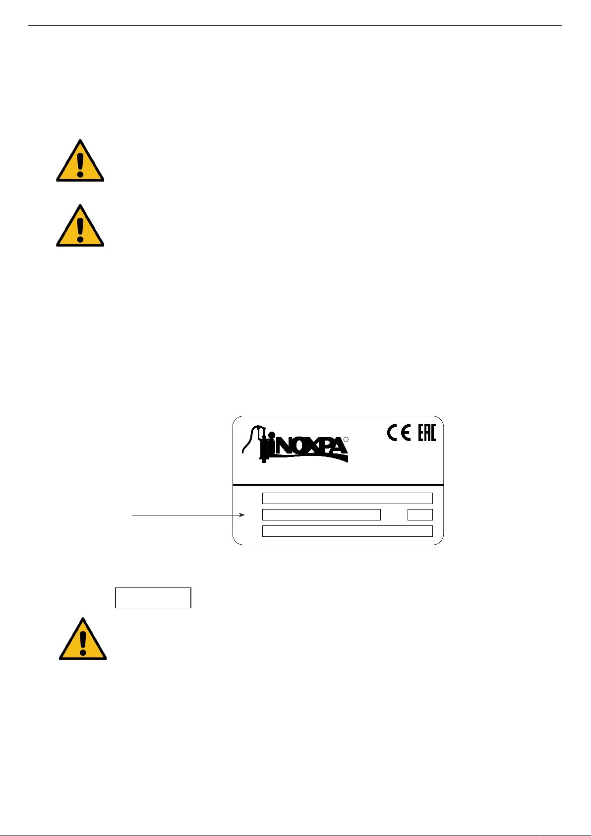
5.2. IDENTIFICATION OF THE MIXER
Each mixer has a nameplate with the basic data required to identify the model:
C. TELERS, 60 - 17820 BANYOLES
GIRONA (SPAIN) . www.inoxpa.com
INOXPA S.A.U.
Type
Year
No
R
Serial number
01.214.32.0014
5.3. TRANSPORT AND STORAGE
The mixers are often too heavy to be stored manually.
Use an appropriate means of transport.
Only authorized personnel should transport the blender.
Do not work or walk under heavy loads.
Lift the mixer as indicated below:
- always use two support points placed as far apart as possible.
ATTENTION
If the mixer is supplied without drive or another element, the purchaser shall be respon-
sible for its assembly, installation, start-up and operation.
Installation
INOXPA S.A.U. 03.100.30.04EN · (0) 2021/05
8

ØD300 400 500 600 800 1000 1200 1600 2000 2500 3000 3500 4000
A20 30 35 40 50 70 80 115 130 180 200 240 280
S5 5 10 10 10 15 20 20 30 30 50 50 50
5.4. LOCATION
Place the mixer in such a way as to facilitate inspections and checks. Leave enough room around the
mixer for service, disassembly and maintenance operations. It is very important to be able to access
the electric connection device of the mixer, even when in operation.
To achieve a good mixing process is possible that it be necessary to place baes in the tank. If this
is the case, consult with INOXPA technical department for each specic application. If necessary, the
approximate dimensions of the baes according to the tank diameter are be indicated in the next
gure and the next table.
During the transport, disassembly or assembly of the mixer, there is a risk of loss of sta-
bility and that the mixer could fall down and cause damages to the operators. Make sure
that the mixer is properly supported.
ATTENTION
See chapter 9. Technical Specications to consult the dimensions and weight of the mixer.
03.100.32.0006
If the mixer is not to be installed immediately, it must be stored in an appropriate place. It must be
stored in a horizontal position and placed on wooden supports or for similar material. In this position,
the shaft will not become deformed since it must not be subject to any type of load.
03.100.32.0012
- secure the supports so that they will not move.
Installation
9
INOXPA S.A.U. 03.100.30.04EN · (0) 2021/05

5.6. ASSEMBLY
In order to assure a good mixing process, the mixer should be positioned at a point corresponding to
1/3 of the tank diameter. Moreover, the distance from the mixer head to the bottom of the tank must
be between 2 and 3 times the diameter of the head.
To do the assembly:
- place the mixer base onto the support ange,
- place the xing screws and nuts to their corresponding holes, without being tightened,
- level the mixer,
• put a spirit level up against the mixer shaft,
• check four points at 90º to each other at which are at the same height,
- Tighten the xing screws and nuts.
Force should never be applied to the end of the mixer shaft, as it can easily suer per-
manent damage.
ATTENTION
5.5. ELECTRICAL INSTALLATION
All the electrical work must be performed by qualied personnel.
Take the appropriate measures to prevent any fault.
The motor must be provided with devices for protection against power overload and
short-circuits.
The mixer cannot be used in areas where there is a risk of re or explosion when this has
not been specied in the order.
To do the electrical installation, connect the motor in accordance with the instructions supplied by
the motor manufacturer following the current national legislation and in compliance with EN 60204-1.
5.6.1. Excessive temperatures
Depending on the uid to be mixed, high temperatures can be reached inside and around the mixer.
Over 68ºC the operator should take protective measures and place warning notices ad-
vising of the danger which exists if the mixer is touched.
The type of protection selected should not isolate the mixer entirely.
Installation
INOXPA S.A.U. 03.100.30.04EN · (0) 2021/05
10
6. Start-up
Before starting the mixer, carefully read the instructions in chapter 5. Installation.
Carefully read chapter 9. Technical Specications. INOXPA will not be liable for improper
use of the equipment.
- Check that the power supply matches the rating indicated on the motor plate.
- Check that the V-ring is not worn or damaged.
- Check the liquid level in the tank. The mixers cannot be operated during the lling or emptying
of the tank. The mixing element has to be submerged to, at the very least, twice its diameter
and must have clearance, with respect to the bottom, of 2 to 3 times the diameter of the head.
- All the guards must be in place.
- The performance of the emulsier mixer depends on the viscosity of the working uid. The
following loading process must be followed in order to use the mixer properly:
• put all of the low viscosity components into the container,
• start up the mixer,
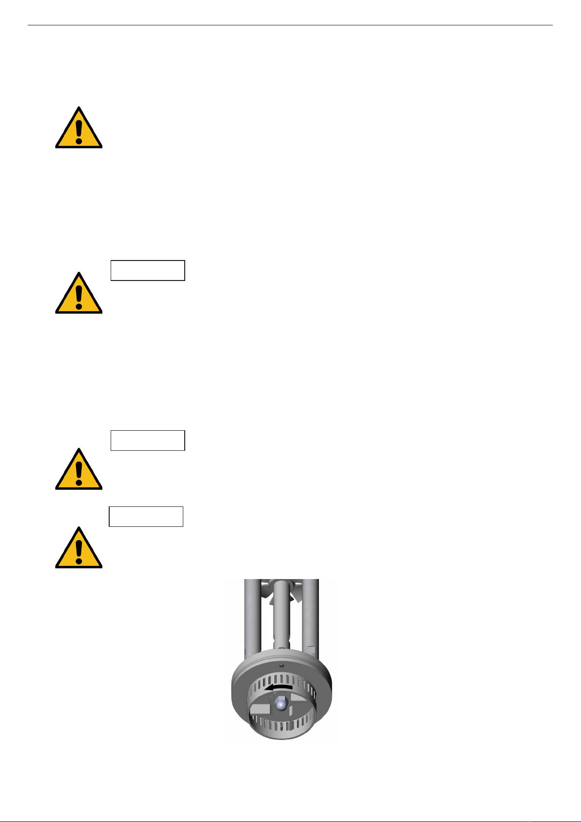
• check that the impeller turn in the right direction. It must turn clockwise as viewed from the
drive side)
The mixer must never turn dry.
ATTENTION
03.100.32.0007
Follow the direction of rotation of the mixing elements as indicated by the arrow attached
to the engine. An incorrect direction of rotations results in a loss of mixer performance.
ATTENTION
Check the mixer direction of rotation since a wrong direction could cause a detachment of
the pieces and later, its projection. This may cause personal damages and/or materials.
ATTENTION
Start-up
11
INOXPA S.A.U. 03.100.30.04EN · (0) 2021/05
Do not modify the operating parameters for which the mixer was initially designed without
written authorisation from INOXPA. Risk of damage or user hazard could arise.
Follow the instructions for use and the safety requirements described in the instructions
manual for the tank in which the mixer is mounted.
If the mixing element is accessible from the top of the tank inspections hatch, then the
user will be exposed to mechanical risks like drag, shear, cutting, impact, attening and
pinching.
ATTENTION
The tank must be tted with protective devices and safety equipment. Consult the manufacturer's
instructions manual.
Introducing an object or solid raw material may cause the mixing component and other
mechanical parts to break and compromise its safety or guarantee.
ATTENTION
Control the motor consumption to prevent an electrical overload.
ATTENTION
Use special protection when the sound pressure in the operation area exceeds 85 dB(A).
• add the remaining liquids or soluble components,
• add the solids that need to be cut or that need a pre-setting time to bring about the reaction,
• add the remaining the components including the solids required to stabilise the formulation
or the solids which are needed to increase the viscosity.
- Check the electrical consumption of the motor.
Start-up
INOXPA S.A.U. 03.100.30.04EN · (0) 2021/05
12

7. Troubleshooting
Motor overload
Insucient mixing
Vibrations and noise
Leaks
PROBABLE CAUSES SOLUTIONS
• • Viscosity of the liquid too high Reduce the viscosity, e.g. by heating the
liquid
•High density Increase motor power
• • Tank too big for the chosen mixer Check with the technical department
•Wrong direction of rotation Change direction of rotation
•Mixer speed too low Increase the speed
•Liquid level insucient or none Check liquid level in the bank
•Shaft bended Replace the shaft
•Critical speed Check with the technical department
• • Worn or damaged bushing Replace the bushing
•Worn or damaged V-ring Replace the V-ring
• • The rotor is rubbing against the stator Replace the bushing
The attached table lists solutions to problems that may arise while operating the mixer. It is assumed
that the mixer has been properly installed and that it has been selected correctly for the specic
application.
Contact INOXPA if technical assistance is required.
Troubleshooting
13
INOXPA S.A.U. 03.100.30.04EN · (0) 2021/05

8. Maintenance
8.1. GENERAL CONSIDERATIONS
8.2. MAINTENANCE
This mixer, just like any other machine, requires maintenance. The instructions contained in this
manual cover the identication and replacement of spare parts. The instructions are aimed at
maintenance personnel and those responsible for the supply of spare parts.
Carefully read chapter 9. Technical Specications.
Maintenance work can only be carried out by qualied personnel that are trained and
equipped with the necessary resources to carry out this work.
All parts or materials that are replaced must be properly disposed of/recycled in
accordance with the current directives applicable in each area.
ALWAYS disconnect the mixer before beginning any maintenance work.
8.3. LUBRICATION
8.4. SPARE PARTS
- Inspect the mixer regularly.
- Do not fail to keep the mixer clean.
- Check the state of the motor.
- Check the V-ring.
- Check the bearing on completing every process. In the event of coming across excessive wear
and tear, it must be changed.
Motor maintenance shall be carried out in accordance with the manufacturer's instructions, see the
instructions manual.
The lubrication of the bearings of the motor will be carried out according to the manufacturer's
instructions.
To order spare parts is necessary to indicate the type and serial number included on the mixer's
characteristics plate, as well as the position and description of the part as found in chapter 9.
Technical Specications.
8.5. CONSERVATION
If the mixer is out of service for a considerable period of time, clean and treat the parts with VG46
mineral oil. The mixer must be stored in the horizontal position and on wooden supports or on
supports of similar material. These supports will be situated on the mixer head.
8.6. DISASSEMBLY AND ASSEMBLY OF THE MIXER
The disassembly and assembly of the mixers should only be carried out by qualied
personnel using only appropriate tools. Ensure that sta read these instructions manual
attentively, particularly the instructions that relate to their work.
Stop the motor from starting up when carrying out assembly and disassembly work on
the mixer.
Place the mixer switch in the “o” position.
Lockout the electrical switchboard or place a warning sign.
Remove the fuses and take them to the workplace.
Maintenance
INOXPA S.A.U. 03.100.30.04EN · (0) 2021/05
14

8.6.1. Disassembly
Once the motor is disconnected, disassembly work may begin.
1. Disassemble the mixer from its emplacement.
2. Clean and dry the mixer.
3. In models ME-1101, ME-1105, ME-1110 and ME-1130, unscrew and retire the rotor.
4. In model ME-1125, remove the rotor nut (54) and retire the rotor. Then, you can retire the rotor
pin (56A) from the extreme of the shaft.
5. Remove the hexagonal screws (52A) with their at washers (53A) to retire the stator (22), the
lower ange (42A) and the bushing (17) from the extreme of the shaft (05).
6. In case that the mixer has a down thrust propeller (02) and recirculation (02A) remove them
unscrewing the allen setscrews (55B).
7. Remove the V-ring (81), the retaining ring (30) and the sleeve (13).
8. Remove the pin of the shaft (56) from the shaft complement (26) and remove the shaft (05).
9. Remove the hexagonal screws (52) with their at washers (53) and remove the motor (93).
The shaft complement (26) still will be xed to the motor. Once the motor is removed, remove
the O-rings (80) from the shaft complement (26) and then, remove the shaft complement (26)
unscrewing the allen setscrews (55,55A).
10. In models ME-1101, ME-1105, ME-1110 and ME-1130, extract the countersunk screws (50) to
separate the structural rods (29) from the upper ange (42).
11. In the model ME-1125, remove the countersunk screws (50) and the lock washers (53B) to
separate the structural rods (29) from the upper ange (42).
12. Unscrew the structural rods (29) from the coupling ange (23).
8.6.2. Assembly
1. Screw the structural rods (29) to the coupling ange (23).
2. In the models ME-1101, ME-1105, ME-1110 and ME-1130, place the structural rods (29) to the
upper ange (42) and x them with the countersunk screws (50).
3. In the models ME-1125, place the structural rods (29) and the lock washers (53B) and x them
with the countersunk screws (50).
4. Place, onto the motor (93) shaft, the shaft complement (26) and x it with the allen setscrews
(55,55A)
5. Mount the motor (93) on the upper ange (42) and x it with the hexagonal screws (52) and
their at washers (53).
6. Situate the shaft (05) in the internal part of the shaft complement (26). The correct situation of
the shaft allows its xation through the shaft pin (56).
7. Place the O-rings (80) on the shaft complement (26).
8. Mount the sleeve (13) on the shaft complement (26) placing the retaining ring (30) to avoid the
displacement of the sleeve.
9. Place the V-ring following the next gure:
03.100.32.0010
10. In the case that the mixer has down thrust propellers (02) and recirculation (02A) place them
on the shaft (05) in their corresponding situation and x them with the allen setscrews (55B).
11. Place the lower ange (42A) and the stator (22) onto the coupling ange (23). These elements
are xed with the hexagonal screws (52A) and their at washers (53A).
12. Slide the bushing (17) onto the shaft (05) until it reaches up to the lower ange (42A).
13. In the model ME-1125, place the rotor pin (56A) in the hole of the extreme of the shaft.
14. In the models ME-1101, ME-1105, ME-1110 and ME-1130, place the rotor (21) on the extreme
of the shaft (05) and with a spanner place at the shaft interface to avoid it turning, screw the
rotor (21).
Maintenance
15
INOXPA S.A.U. 03.100.30.04EN · (0) 2021/05

15. In the model ME-1125, face the rotor (21) in the rotor pin (56A), place the rotor washer (35) and
x the rotor with its nut (54).
16. Mount the mixer in its emplacement.
Maintenance
INOXPA S.A.U. 03.100.30.04EN · (0) 2021/05
16
9. Technical Specications
Materials
Parts in contact with the product 1.4404 (AISI 316L)
Bushing PTFE
V-ring NBR
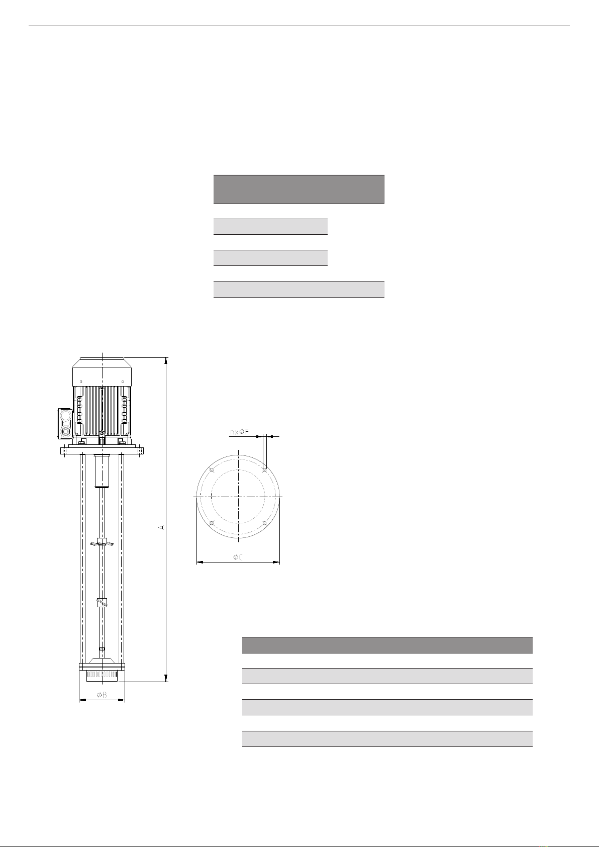
9.1. WEIGHTS AND DIMENSIONS
Mixer Power
(kW)
Speed
(rpm)
ME-1101 1,1
3000
ME-1103 2,2
ME-1105 4
ME-1110 7,5
ME-1125 18,5
ME-1130 22 1500
Mixer A (mm) ØB (mm) ØC (mm) Weight (kg)
ME-1101 1010 125 250 29
ME-1103 1080 125 250 36
ME-1105 1205 170 310 65
ME-1110 1660 185 360 115
ME-1125 1920 210 430 200
ME-1130 2080 290 430 350
03.100.32.0008
Mixer base
Technical Specications
17
INOXPA S.A.U. 03.100.30.04EN · (0) 2021/05

9.2. TECHNICAL SECTION AND PARTS LIST
03.100.32.0009
Detail ME-1125
Technical Specications
INOXPA S.A.U. 03.100.30.04EN · (0) 2021/05
18

Position Description Quantity Material
02 downthrust propeller 1 1.4404 (AISI 316L)
02A recirculation propeller 1 1.4404 (AISI 316L)
05 rotor shaft 1 1.4304 (AISI 316L)
13 coupling sleeve 1 1.4304 (AISI 316L)
17 bushing11 PTFE
21 rotor 1 1.4304 (AISI 316L)
22 stator 1 1.4304 (AISI 316L)
23 coupling ange 11.4304 (AISI 316L)
26 shaft complement 1 1.4304 (AISI 316L)
29 structural rod 4 1.4304 (AISI 316L)
30 retaining ring 1 1.4304 (AISI 316L)
35 rotor washer21 A2
42 upper ange 11.4304 (AISI 316L)
42A lower ange 11.4304 (AISI 316L)
50 countersunk screw 4 A2
52 hexagonal screw 4 A2
52A hexagonal screw 2 A2
53 at washer 4 A2
53A at washer 2 A2
53B lock washer 4 A2
54 rotor nut 1 1.4304 (AISI 316L)
55 allen setscrew 3 A2
55A allen setscrew 1 A2
55B allen setscrew 2 A2
56 shaft pin 1 1.4304 (AISI 316L)
56A rotor pin 1 1.4304 (AISI 316L)
80 O-ring12 NBR
81 V-ring11 NBR
93 motor 1 -
1) recommended spare parts
2) only in the model ME-1125
Technical Specications
19
INOXPA S.A.U. 03.100.30.04EN · (0) 2021/05
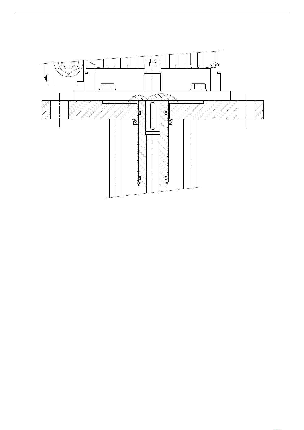
9.3. V-RING SEALING DETAIL
03.100.32.0010
Technical Specications
INOXPA S.A.U. 03.100.30.04EN · (0) 2021/05
20
This manual suits for next models
6
Table of contents
Other INOXPA Mixer manuals


