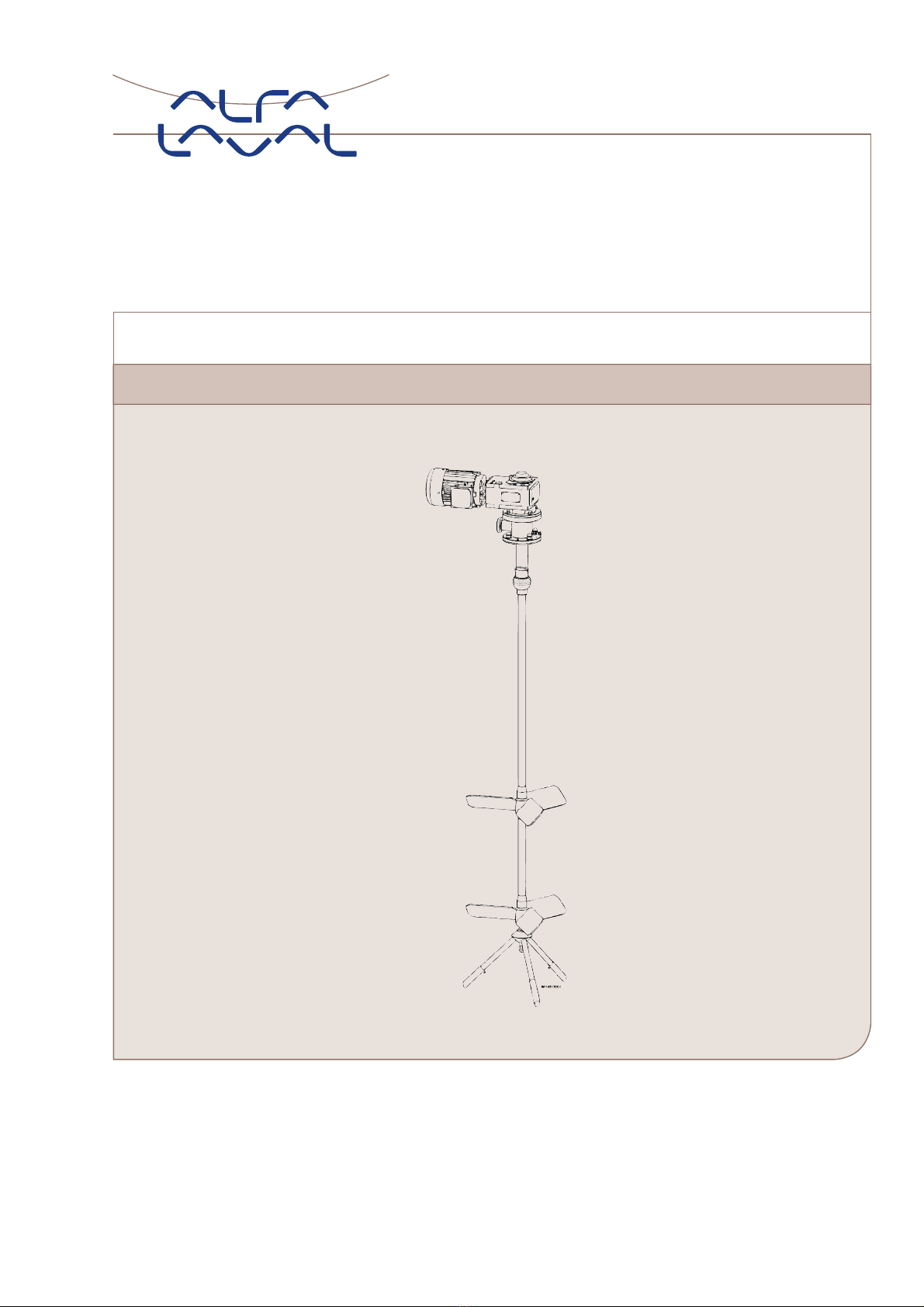
Alfalaval ALTB-SB-20 User manual
ESE03056-EN6 2020-05
Original manual
Instruction Manual
ALTB-SB-20


Table of contents
The information herein is correct at the time of issue but may be subject to change without prior notice
1. EC Declaration of Conformity ....................................................................... 4
2. Safety .................................................................................................... 5
2.1. Important information ............................................................................. 5
2.2. Warning signs ..................................................................................... 5
2.3. Intended use ...................................................................................... 5
2.4. Safety precautions ................................................................................ 6
3. Installation .............................................................................................. 7
3.1. Unpacking/delivery ............................................................................... 7
3.2. Requirement for installation, personnel ......................................................... 8
3.3. Installation (with cutting/machining and welding required) ..................................... 8
3.4. Installation (assembling) .......................................................................... 12
3.5. Installation, electrically ............................................................................ 19
3.6. Recycling information ............................................................................. 19
4. Operation ............................................................................................... 20
4.1. Operation .......................................................................................... 20
4.2. Inspection ......................................................................................... 20
4.3. Troubleshooting ................................................................................... 20
4.4. Cleaning ........................................................................................... 21
5. Maintenance ........................................................................................... 22
5.1. General Maintenance ............................................................................. 22
5.2. Disassembling of agitator ........................................................................ 22
5.3. Replacement of gear motor ..................................................................... 22
5.4. Replacement of seals ............................................................................ 22
5.5. Replacement of Bearing for bottom console ................................................... 22
6. Technical Data ......................................................................................... 23
6.1. Technical data ..................................................................................... 23
7. Parts list / Service kits ................................................................................ 24
7.1. ALTB-SB-20-AE (with aeration) ................................................................. 24
7.2. ALTB-SB-20 (without aeration) .................................................................. 26
7.3. ALTB-SB-20 (with and without aeration) ....................................................... 27
7.4. Mounting Tools .................................................................................... 36
7.5. Installation Drawings .............................................................................. 38
8. Appendix ............................................................................................... 41
8.1. Declaration of Compliance ....................................................................... 41
8.2. Order specific “Tank With Agitator” drawing, example ........................................ 42
8.3. WPS ................................................................................................ 43
8.4. Drive unit lubrication .............................................................................. 44
8.5. Drive unit instruction .............................................................................. 49
3

1 EC Declaration of Conformity
Revision of Declaration of Conformity: 2017-03-01
The Designated Company
Alfa Laval KoldingA/S
Company Name
Albuen 31, DK-6000 Kolding, Denmark
Address
+4579322200
Phone No.
hereby declare that
ALTB-SB
Designation
20
Type
Serial number from AAC000000001 to AAC999999999
is in conformity with the following directive with amendments:
Machinery Directive 2006/42/EC
FDA 21CFR§177
Regulation (EC) 1935/2004
The person authorised to compile the technical file is the signer of this document.
Global Product Quality Manager, Pumps, Valves, Fittings and Tank Equipment Lars Kruse Andersen
Title Name
Kolding 2020-02-01
Place Date (YYYY-MM-DD) Signature
4
2 Safety
Unsafe practices and other important information are emphasized in this manual.
Warnings are emphasized by means of special signs.
2.1 Important information
Always read the manual before using the agitator!
WARNING
Indicates that special procedures must be followed to avoid serious personal injury.
CAUTION
Indicates that special procedures must be followed to avoid damage to the Agitator.
NOTE
Indicates important information to simplify or clarify procedures.
2.2 Warning signs
General warning:
Caustic agents:
Dangerous electric voltage:
2.3 Intended use
- The Agitator in only for mixing / conditioning / stirring of liquids in a tank.
- The Agitator is only made for top mounting position on the top plate / welding flange on the tank.
5
2 Safety
All warnings in the manual are summarised on this page.
Pay special attention to the instructions below so that serious personal injury and/or damage to the valve are avoided.
2.4 Safety precautions
2.4.1 Installation:
Always read the technical data thoroughly (see 6 Technical Data).
Always follow installation instructions thoroughly (see 3 Installation).
Never expose the Agitator to undue vibrations or shocks.
Never start the Agitator in the wrong direction of rotation.
Ensure that the tank media is not corrosive to the Agitator.
Only install the Agitator in environments within temperature limit: -20°C and +40°C.
Only install the Agitator in altitudes less than 1000 m above sea level.
Only use authorized personnel when electrically equipment is connected.
2.4.2 Operation:
Always read the technical data thoroughly (see 6 Technical Data).
Never start Agitator in the wrong direction of rotation.
Beware of Agitator in operation can produce sound levels in excess of 85dB(A).
Always handle lye and acid with great care.
Always rinse well with clean water after cleaning.
Never run the agitator for a longer time (seconds) without product, water or cleaning liquid in the tank.
2.4.3 Maintenance:
Always follow the maintenance instruction thoroughly (see 5 Maintenance.)
Always follow the maintenance instruction for gear motor thoroughly (see 8.5 Drive unit instruction).
Always study the parts list and assembly drawing carefully (see 7 Parts list / Service kits).
Never touch the moving parts while the Agitator is connected to the power supply.
Always disconnect the power supply while servicing the Agitator.
Ensure correct rotation direction of propeller before startup and after any maintains there might have impact on
the direction.
Never service the agitator or tank with product or cleaning liquid in the tank.
2.4.4 Transportation:
Always transport the Agitator in original packaging.
Always support the shaft adequately, to protect shaft and bearings.
Never expose the Agitator to undue vibrations or shocks.
Control for oil leakage on gears with vent screw.
Ensure correct rotation direction of impeller before startup and after any maintains there might have impact on the
direction.
6
3 Installation
The instruction manual is part of delivery. Study the instructions carefully.
The Agitator is for permanent fastening.
Make sure the motor corresponds to the environment.
Check the direction of rotation before operation.
3.1 Unpacking/delivery
Always use lifting equipment when handling the Agitator.
Alfa Laval cannot be responsible for incorrect unpacking.
Step 1
3.1.1 Inspect the delivery for visible transportation damage (crates and packaging) - all issues should be reported to carrier.
Step 2
3.1.2 Check that deliveries are according to delivery notes.
Complete Agitators can be delivered in more than one shipment.
Agitators can be delivered as one of the following:
1. Agitator parts and instruction manual required for tank builder to install shafts and propellers.
2. Agitator parts and instruction manual required for tank builder to install drive unit (gear motor) and sealing system.
3. As 1) and 2) in one shipment.
Step 3
3.1.3 Inspect Agitator parts for visible transport damage.
Step 4
Do NOT use eye bolts on gear motor to lift the Agitator. They are only for gear motor removal.
Step 5
3.1.5 During lifting:
- Always support the shaft adequately to protect shaft and bearings.
- Be carefully not to damage shaft-end with treads.
- Never expose the Agitator to undue vibrations or shocks.
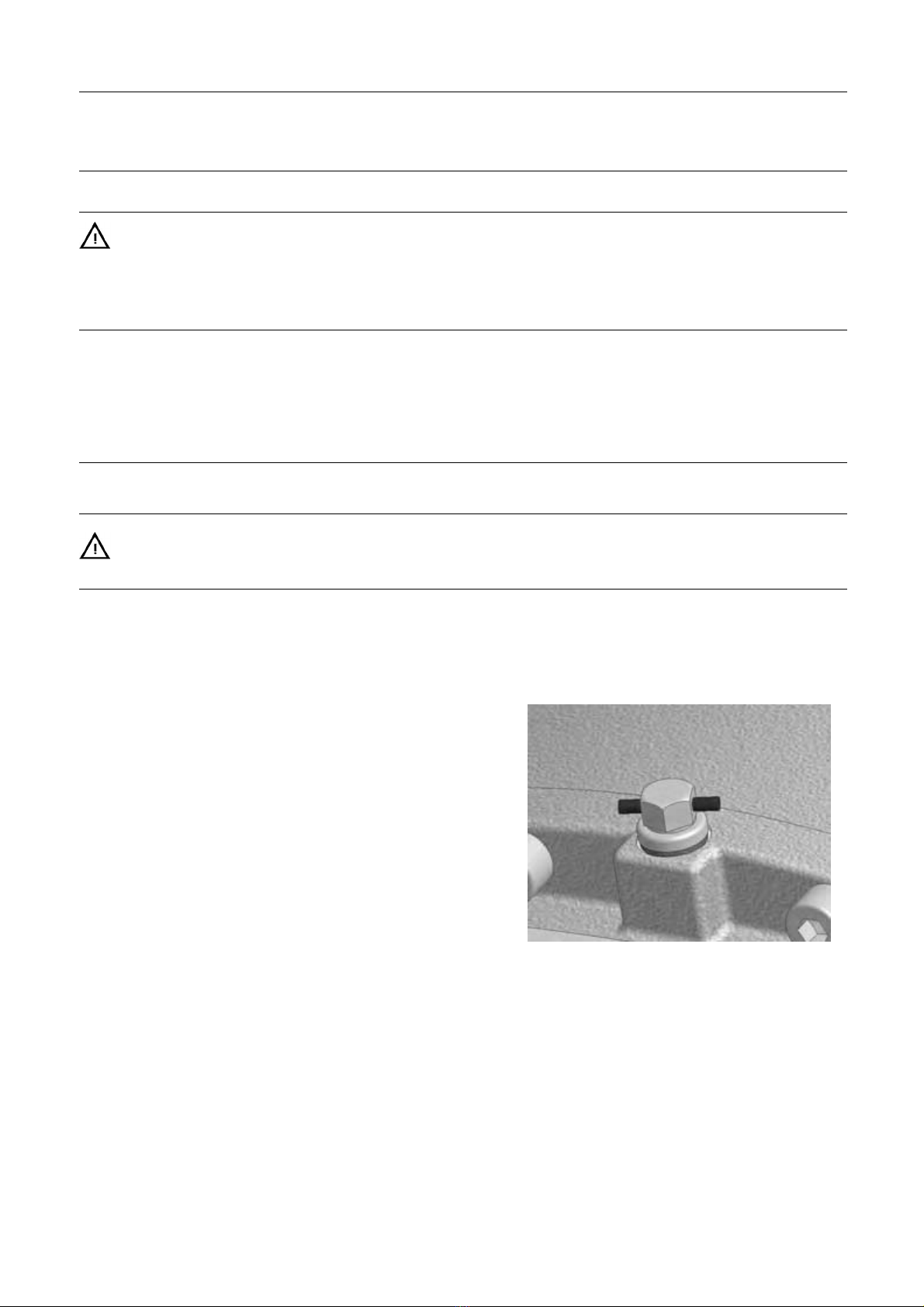
- Control for oil leakage on gears – leave vent plug in gear until gear is installed and in correct position.
Figure 1, un-activated vent plug
7

3 Installation
The instruction manual is part of delivery. Study the instructions carefully.
The Agitator is for permanent fastening.
Make sure the motor corresponds to the environment.
Check the direction of rotation before operation.
3.2 Requirement for installation, personnel
Welder:
Experience from similar types of installation, covering TIG, MIG and MAG welding procedures in stainless steel thin
walled material.
Proven skills in reading installation guidelines and drawings ensuring that the installation is carried out safe for personnel
and property.
Erectors:
Experience from similar types of installation.
Proven skills in reading installation guidelines and drawings ensuring that the installation is carried out safe for personnel
and property.
Electrician:
Certified according to local regulations and experience from similar types of installation.
Proven skills in reading installation guidelines and drawings ensuring that the installation is carried out safe for personnel
and property.
3.3 Installation (with cutting/machining and welding required)
3.3.1 Requirement for installation
This work should be carried out by at least two persons and for safety reasons a platform or a scaffold should be
established around the tank top.
During installation ensure to use sufficient lightning.
The tank top must be horizontally during installation – if that is not the case, a laser must be used to ensure that the
right position for the “Bottom Console” can be found.
Ensure that the tank does not contain neither dangerous liquid nor gasses and that good ventilation is established.
Always have safety elements removed by authorized personnel.
Never cover or remove nameplates.
Always use lifting equipment when handling heavy parts of the Agitator.
Never connect to power during installation.
Always have the Agitator connected to power supply by authorized personnel.
Note: Alfa Laval highly recommends installing motor protection guard to the Agitator.
All position numbers and item numbers refer to the drawings show and specified in 7 Parts list / Service kits
8

3 Installation
The instruction manual is part of delivery. Study the instructions carefully.
The Agitator is for permanent fastening.
Make sure the motor corresponds to the environment.
Check the direction of rotation before operation.
Step 1
3.3.2
See illustration in 7.5.1 page 38.
A. The three “Adjustable Leg For Bottom Console” pos. 70 are fastened to the “Bottom Console for Agitator” pos. 74 using
the three “Screw” pos. 77.
B. The assembled “Bottom Console” from a)
“Guide spindle for bearing” pos. 69
“Tool – Bushing” pos. 83,
“Tool – Back stop” pos. 85,
“Screw” pos. 91,
“Propeller” pos. 73,
“Agitator Shaft” pos. 71 (if delivered),
“Propeller” pos. 72 (if delivered),
“Agitator Shaft” pos. 75,
are lowered into the tank and assembled. In some cases all the parts can be assembled outside the tank and lowered into
the tank assembled. All threads must be greased to ensure not to damage the threads.
C. According to the order specific drawing "Agitator with Tank" that comes with the manual (not in the manual) the correct
Agitator position is selected (0/125/175 mm off center) which specify which position of holes to be used (data in this
manual are not to be used – find order specific drawing).
Example of an order specific drawing "Order specific "Tank With Agitator" drawing, example" are to be found in 8.2, page 42.
D. Mount the “Tool Guide Plate” pos. 80 on the “Tank mounting flange” pos. 99 letting the shaft pos. 75 entering the correct
hole in pos. 80. The “Tool Guide Plate” must be fastened to the tank top using two diagonally located holes in the tank top.
E. Mount the “Tool – Top Guide” pos. 82 to the “Tool Guide Plate” pos. 80 using the four “Screw” pos. 88.
F. Mount the “Tool – Top Guide” pos. 81 into the “Tool – Top Guide” pos. 82.
G. Rotate / orientate pos. 82 enabling the “Screw” pos. 90 to be used to fasten the shaft in vertical direction during adjustment
of the “Bottom Console” pos. 74.
9
3 Installation
The instruction manual is part of delivery. Study the instructions carefully.
The Agitator is for permanent fastening.
Make sure the motor corresponds to the environment.
Check the direction of rotation before operation.
Step 2
3.3.3 See illustration in 7.5.1 page 38.
A. If the tank top is horizontally within 0,5° the gravity can be used
as guideline for position of the “Bottom Console” – if it is not
possible to adjust the tank top to horizontally position (within
the tolerance) a laser pointer must be used to ensure that the
right position for the “Bottom Console” is found.
B. The Agitator is lifted to the correct position as shown on the
order specific drawing “Tank with Agitator” that comes with
the manual (not in the manual).
Example of an order specific drawing "Order specific "Tank
With Agitator" drawing, example" are to be found in 8.2, page
42. The “Screw” pos. 90 is tightened (not more than sufficient)
to fasten the shafts in vertical position.
C. When the agitator shaft is in correct position the three
“Adjustable Leg For Bottom Console” pos. 70 are
adjusted/rotated facing the tank bottom and the three “Screws”
pos. 77 are fastened. If the legs on “Bottom Console for
Agitator”pos. 74aretoolongtheyarecuttotherequired
length.
D. Tag weld the three “Adjustable Leg For Bottom Console” pos.
70 to the tank bottom using TIG welding.
E. Untighten the “Screw” pos. 90 ensure that the shaft can rotate
freely.
F. Tighten the screw again.
G. Remove one “Screw” pos. 77 and fill the thread hole with
welding, continue one by one with the two other screws.
H. Remove the “Screw” and pos. 90.
I. Verify that the shaft can rotate freely.
J. Grind the welded seams to the required finish.
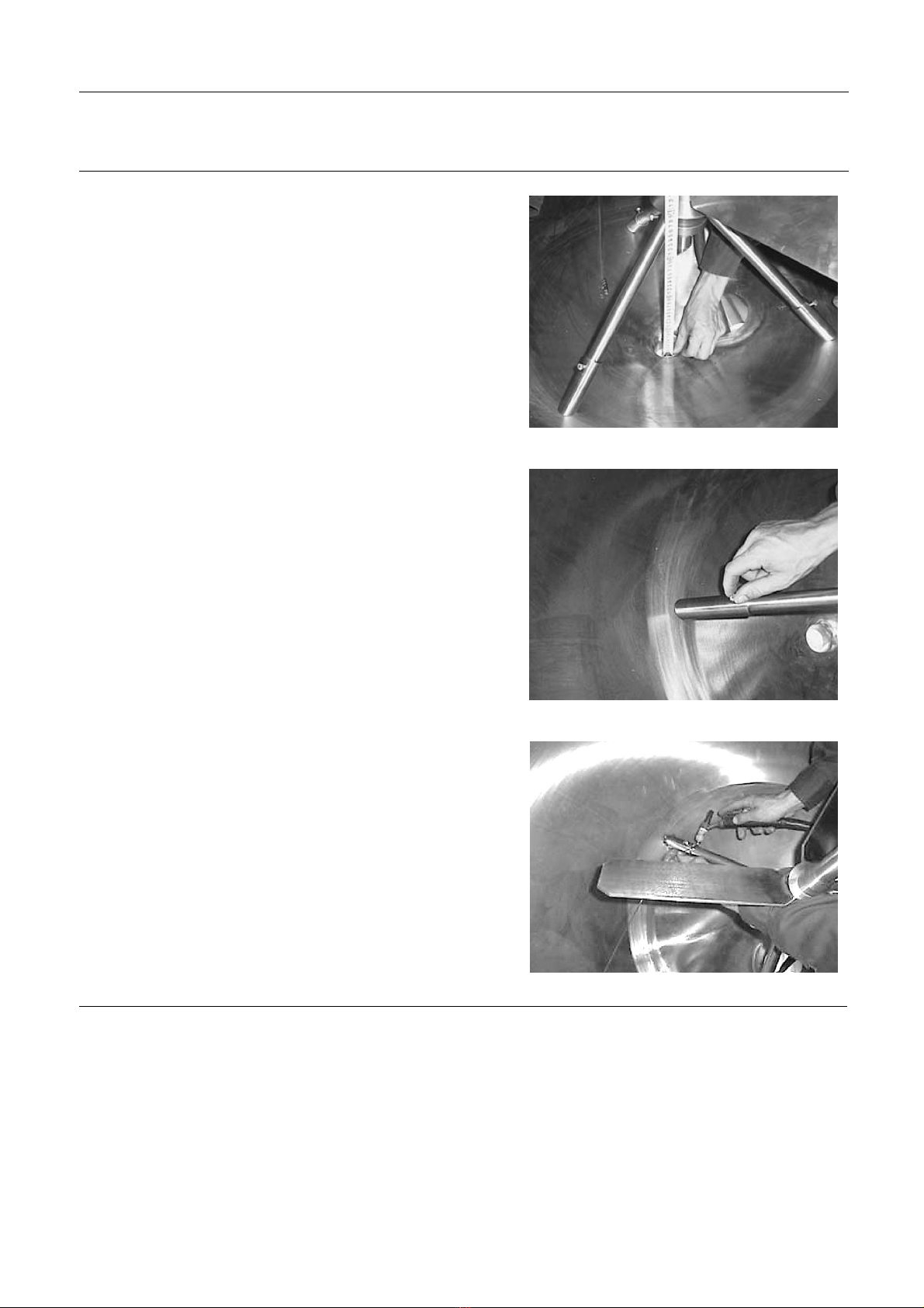
Figure 2, Height of Bottom Console
Figure 3, Tightening screws
Figure 4, Welding Bottom Console
10

3 Installation
The instruction manual is part of delivery. Study the instructions carefully.
The Agitator is for permanent fastening.
Make sure the motor corresponds to the environment.
Check the direction of rotation before operation.
Step 3
3.3.4 See illustration and Parts List in 7.5.1 and 7.5.3.
A. Using a permanent pen do a marking line at position ∆1as
shownon7.5.1.page38ontheshaftpos.75.
B. Verify that the line is at the same vertical position as the
upper surface of the tank top flange (welding flange) pos.
99.
C. Remove the “Tool” parts pos. 88, 82, 81, 80.
D. Using the equation: X1 = “Thickness of Gasket, pos. 101” +
“Thickness of Top Plate, pos. 100”, mark the cutting line ∆2.
e.g:
Thickness of Gasket = 5 mm
Thickness of Top Plate = 20 mm
X1=5+20=25m
if an O-ring is used as gasket the “Thickness of Gasket” = 0
E. The “Agitator Shaft” is delivered longer than needed and
should be shortened to no more than 300 mm. If it must be
shortened more, the inside diameter must be machined to
fit the “Shaft, Upper for Agitator” pos. 76 outer diameter
within a 0,1 mm tolerance.
F. Cut the “Agitator Shaft” pos. 75 at the cutting line ∆2.
G. Press the “Shaft, Upper for Agitator” pos. 76 onto the
“Agitator Shaft” pos. 75 firmly and ensure that it is aligned
with the shaft.
H. Weld it as shown on 7.5.1 page 38 and in WPS in 8.3,
page 43.
I. Grind the welded seams to the required finish.
Figure 5, Marking of pos.∆1
Step 4
3.3.5
A. Unscrew and disassembly the shafts and propeller unit – label all the parts carefully with item number and tank number.
B. Arrange careful transportation of the tank and the agitator parts to the destination.
11
3 Installation
The instruction manual is part of delivery. Study the instructions carefully.
The Agitator is for permanent fastening.
Make sure the motor corresponds to the environment.
Check the direction of rotation before operation.
3.4 Installation (assembling)
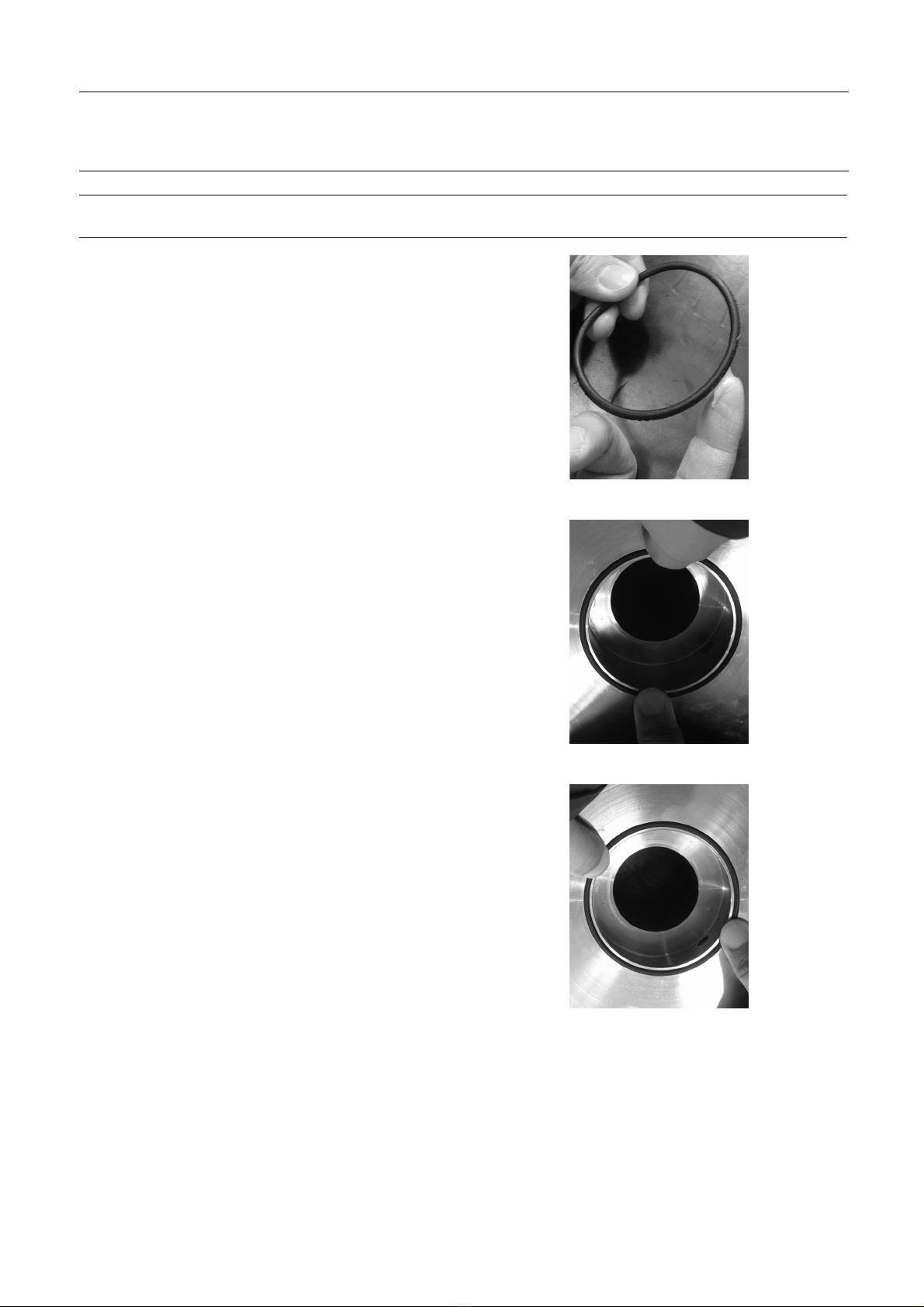
3.4.1 Mounting of O-Rings in general
A. Apply some food-approved grease to the O-ring
Figure 6, Greasing O-ring
B. Press the O-ring into the appropriated groove at position 0°
and 180°
Figure 7, Inserting O-ring
C.Press the O-ring into the appropriated groove at position 90°
and 270°
Figure 8, Inserting O-ring
12

3 Installation
The instruction manual is part of delivery. Study the instructions carefully.
The Agitator is for permanent fastening.
Make sure the motor corresponds to the environment.
Check the direction of rotation before operation.
Step 5
3.4.2 See illustrations, 7.1, 7.2, and 7.5.3.
A. Mount the “Bearing For Bottom Console” pos. 25 into the “Bottom Console” pos. 74.
B. Clean all shafts, propellers and Guide Spindel (pos. 69) threads for grease.
C. Assemble the shaft and propeller unit inside the tank with gaskets, o-rings and Loctite®: pos. 24, 30, 35, 69, 71, 72, 73, 75,
76 and slide it carefully down/into the “Bottom Console pos. 74” with the “Bearing For Bottom Console” pos. 25.
D. Avoid hard bumping against the bottom console bearing.
E. Tighten all threads till 100-200 Nm.
F. Mount the “Gasket” pos. 101 and the “Top Plate” pos. 100 – tight with a couple of screws.
G. Press the “Spray Ball Bearing” pos. 26 into the “Spray ball”, pos. 8.
H. Mount the “Spray ball” pos. 8 (incl. the “Spray ball Bearing” pos. 26) onto the “Tube, CIP for Spray Ball” pos. 3 using the
“Spring lock for spray ball” pos. 9
I. In some cases all the parts can be assembled outside the tank and lowered into the tank assembled.
J. Insert the “O-Ring” pos. 33 into the “Tube, CIP for Spray Ball” pos. 3.
K. Position the “Tube, CIP for Spray Ball” pos. 8 onto the “Top Flange” pos. 100.
13

3 Installation
The instruction manual is part of delivery. Study the instructions carefully.
The Agitator is for permanent fastening.
Make sure the motor corresponds to the environment.
Check the direction of rotation before operation.
Step 6
3.4.3 If without Aeration go to Step 7.
If with Aeration continue below:
See illustrations, 7.1, 7.2, and 7.5.3.
A. Position the “Spring guide” pos. 7
B. Press in the “Pressure spring” pos. 6 on the “Aeration seal box” pos. 27 and insert the two “O-rings” pos. 34 and 36
using some food approved grease.
C. Add some food-approved grease to the shaft pos. 76 and slide the parts on the shaft and position them as shown below.
14
3 Installation
The instruction manual is part of delivery. Study the instructions carefully.
The Agitator is for permanent fastening.
Make sure the motor corresponds to the environment.
Check the direction of rotation before operation.
Step 7
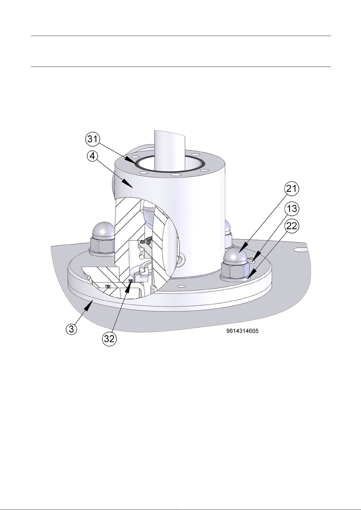
3.4.4 See illustrations, 7.1, 7.2, and 7.5.3.
A. Press in the two “Guide Pin” pos. 13 into the “Console for Agitator”, pos. 4.
B. Press in the two “O-ring” pos. 31 and pos. 32 into pos. 4.
C. Mount the “Console for Agitator”, pos. 4 on the “Tube, CIP for Spray Ball” pos. 3.
D. Using the appropriate screws and Loctite®, the four washers pos. 22 and four nuts pos. 21 are sequentially tightened
to about 200 Nm.
15

3 Installation
The instruction manual is part of delivery. Study the instructions carefully.
The Agitator is for permanent fastening.
Make sure the motor corresponds to the environment.
Check the direction of rotation before operation.
Step 8
3.4.5 See illustrations, 7.1, 7.2, and 7.5.3.
The Mechanical seal pos. 28 (28.1, 28.2, 28.3, 28.4, 28.5, 28.6) consist of several parts as labelled below – the parts cannot be
ordered separately – only as one complete mechanically seal pos. 28.
A. Add some food-approved grease to the O-ring pos. 28.2 and mount it on the stationary seal ring pos. 28.1.
B. Press both parts (pos. 28.1 and pos. 28.2) into the “Flange, Upper” pos. 5.
C. Add some food-approved grease to the O-ring pos. 28.4 and slides the parts pos. 28.3, 28.4, 28.6 and 28.5 onto the shaft.
D. Mount the “Flange, Upper” pos. 5 onto the “Console for Agitator” pos. 4 – ensure that it is positioned rotation-wise
as required.
E. Press in the two “Guide Pin” pos. 12.
F. Add some Loctite®to the four screws pos. 19, mount them with the “Washers” pos. 16 and tighten the screws sequentially
to 51 Nm.
G. Mount the “Parallel Key” pos. 78 using the “Screw” pos. 79.
Figure 9, Greasing 28.4
Figure 11, 28.1 and 28.2
Figure 10, 28.1, 28.1 and 5
16

3 Installation
The instruction manual is part of delivery. Study the instructions carefully.
The Agitator is for permanent fastening.
Make sure the motor corresponds to the environment.
Check the direction of rotation before operation.
Step 9
3.4.6 See illustrations, 7.1, 7.2, and 7.5.3.
A. The shaft-end surface pos. 76 and the hollow shaft surface of the gear motor pos. 2 are cleaned and gently greased.
B. The gear motor pos. 2 is gently lowered onto the “Flange, Upper” pos. 5 using a hoist.
C. The screws pos. 15, washers pos. 16 and nuts pos. 20 are mounted using some Loctite®and tightened till 51 Nm.
17
3 Installation
The instruction manual is part of delivery. Study the instructions carefully.
The Agitator is for permanent fastening.
Make sure the motor corresponds to the environment.
Check the direction of rotation before operation.
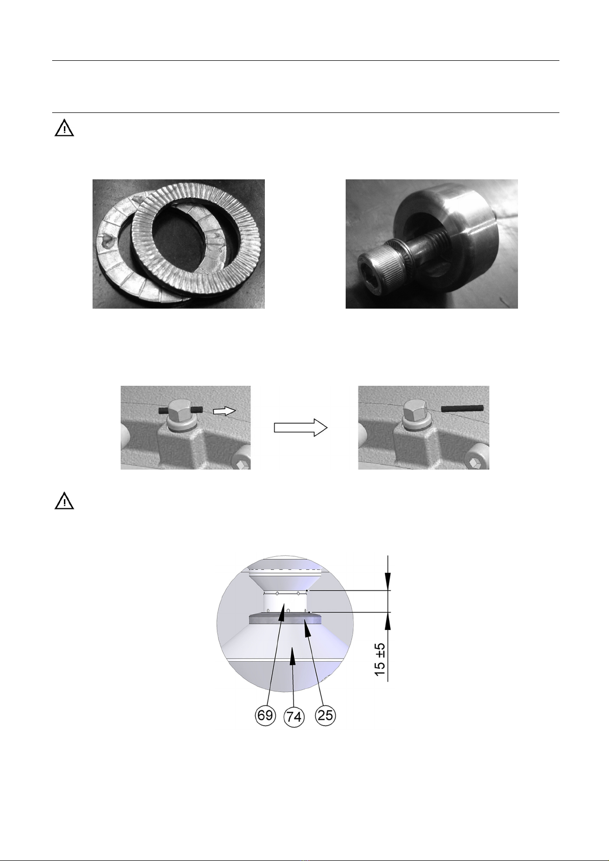
D. The washer pos. 18 consists of two parts attached to each other with some silicone as shown on the picture. It is important
that the parts are positioned as shown.
E. The bushing that follows the gear motor seen on the picture is used to fasten the shaft into the gear motor.
Figure 13, One washer pos. 22 Figure 12, Bushing for shaft / gear motor
F. The screw pos. 17 is tightened (without using Loctite®)to51Nm.
G. The cover that follows the gear motor is mounted on the gear motor covering the shaft and bushing and tightened.
H. The oil vent plug is activated on the gear motor (see below and 8.5 “Drive Unit Instructions”).
Figure 14, Activation of gear vent plug
I. Use of gear motor covers is not permitted due to risk of reduced cooling on motor.
J. Verify that the distance between “Bearing for bottom Console” pos. 25 top and the lower part of “Guide spindle for bearing”
pos. 69 is about 15 mm as shown below and 7.5.3 “Complete Agitator In Tank”.
Figure 15, Installation verification
18
3 Installation
The instruction manual is part of delivery. Study the instructions carefully.
The Agitator is for permanent fastening.
Make sure the motor corresponds to the environment.
Check the direction of rotation before operation.
3.5 Installation, electrically
- Operation by unauthorized personnel may endanger personnel and property.
- Treat all electrical equipment as powered.
- Switch off the power before maintenance and repair.
- The electrician must be certified according to local regulations and with at least 3 years’ experience from similar types of
installations.
- The electrician must have proven skills in reading and working from drawings and cable lists.
- The electrician must have knowledge of local safety regulations for power and automation and making sure that any work
carried out is safe for personnel and property before the equipment is put back into operation.
If you need assistance or have questions – please contact Alfa Laval.
- The motor requires the power supply as indicated on the name plate.
- It is recommended to secure the motor with a motor protection.
- We recommend starting the motor by use of a soft starter with a start ramp up time of 2-7.5 sec.
- We recommend installation of a service switch at the agitator to secure the personnel during service work.
- Perform a visual inspection of the direction of rotation. The direction required is indicated on the name plate.
- Rotation of agitator must be clockwise. Otherwise the agitator will be damaged.
3.6 Recycling information
• Unpacking
- Packing material consists of wood, plastics, cardboard boxes and in some cases metal straps.
- Wood and cardboard boxes can be re-used, recycled or used for energy recovery.
- Plastics should be recycled or burnt at a licensed waste incineration plant.
- Metal straps should be sent for material recycling.
• Maintenance
- During maintenance, oil and wear parts in the machine are replaced.
- All metal parts should be sent for material recycling.
- Worn out or defective electronic parts should be sent to a licensed handler for material recycling.
- Oil and all non-metal wear parts must be disposed of in accordance with local regulations.
• Scrapping
- At the end of use, the equipment must be recycled according to the relevant, local regulations. Besides the equipment itself,
any hazardous residues from the process liquid must be considered and dealt with in a proper manner. When in doubt, or in
the absence of local regulations, please contact your local Alfa Laval sales company.
19

4Operation
Study the instructions carefully and pay special attention to warnings! Always check the Agitator before operation. Alfa Laval
recommends a soft starter for the Agitator to reduce the load on tank and Agitator.
4.1 Operation
Rotation of agitator must always be clockwise.
Use of gear motor covers is not permitted due to risk of reduced cooling on motor.
If batch rotation is observed during operation, the optimum effect of the agitator is achieved by interval agitation. If interval
agitation is used, the gear motor must be installed with a soft-starter to increase gear motor life time and reduce forces on the
tank system.
If a sensitive product is processed, agitation speed and time should be reduced as much as possible.
If the agitator is equipped with an aeration valve, it is possible to aerate the product through the shaft during the agitation.
4.2 Inspection
Part Inspection Interval
Gear motor
- Clean surfaces to avoid overheating
- Check for oil leakages Monthly
Monthly
Sealing
- Verify that the seals are not leaking Monthly
Bottom console bearing
- Check for wear – radial movement < 5 mm Semi-annually
4.3 Troubleshooting
Problem Cause/result Remedy
Not starting
Gear motor - Defect - Dismantle gear motor, check for
correct rotation
- Replace gear motor
- Fault at power supply - Check power supply connection
- Check voltage and frequency
correspond with motor name plate
- Check frequency converter adjustment
correspond with motor name plate
Agitator - Obstructed - Check that Agitator can rotate freely
without striking anything
Vibrations
Guidance - Bottom Console Bearing - Change Bearing / Bushing
Propeller -Dam
aged
-Un
balanced - Contact Alfa Laval
- Clean propeller
Shaft - Damaged - Contact Alfa Laval
Unusual sounds
Guidance - Shaft rotation – radial movement > 5 mm - Change Bearing / Bushing
Leakage
Gear motor - Oil leakage
- CIP fluid or other from drain - Renovate or change gear motor
- Replace sealing
Performance - Deviation from normal operation - Operation must be according to
specification
20
Other manuals for ALTB-SB-20
1
Table of contents
Other Alfalaval Mixer manuals

Alfalaval
Alfalaval ALT series User manual

Alfalaval
Alfalaval HPM M-15 User manual

Alfalaval
Alfalaval LeviMag User manual

Alfalaval
Alfalaval IM 20 User manual

Alfalaval
Alfalaval MM UltraPure User manual

Alfalaval
Alfalaval ESE02185-EN8 User manual

Alfalaval
Alfalaval IM 15 User manual

Alfalaval
Alfalaval ALS User manual

Alfalaval
Alfalaval ALT User manual

Alfalaval
Alfalaval IM 15 User manual


