InPlay IN1BN-DKC0-100-C0 User manual

Specifications and information are subject to change without notice.
Inplay NanoBeacon™
IN100 Development Kit
User Manual

1 / 10
InPlay NanoBeacon™ IN100 Development Kit User Manual
Contents
About Documentation ................................................................................... 3
1. General Description .................................................................................4
2. Hardware Description.............................................................................. 6
3. Schematic................................................................................................ 9
4. Revision History ......................................................................................10
5. Legal Disclaimer......................................................................................10

2 / 10
InPlay NanoBeacon™ IN100 Development Kit User Manual
List of Figures
FIGURE 1:DEVELOPMENT KIT ....................................................................................... 4
FIGURE 2:DEVELOPMENT BOARD................................................................................. 5
FIGURE 3:PROGRAMMER BOARD .................................................................................. 5
FIGURE 4:PROGRAMMER BOARD .................................................................................. 6
FIGURE 5:PROGRAMMER BOARD .................................................................................. 8
FIGURE 6:DEVELOPMENT KIT SCHEMATIC ................................................................... 9
3 / 10
InPlay NanoBeacon™ IN100 Development Kit User Manual
About Documentation
Product Status
Document Content
Data Status
In Development
Target specification / MRD
Initial release
Engineering
Document
Main functions and features
description
Preliminary version
Official Release
Document
Description of all functional
features
Subject to revision and updates
This document applies to the following products:
Document
Applicable Products
Document Status
InPlay NanoBeacon™
IN100 Development Kit
User Manual
IN1BN-DKC0-100-C0
Engineering Document
Document Name
InPlay NanoBeacon™IN100 Development
Kit User Manual
Part number
IN1BN-DKC0-100-C0
Control Number
IN1EDOC-HW-IN1BN-EN-V1_0
External User
Revision
V1.0
4 / 10
InPlay NanoBeacon™ IN100 Development Kit User Manual
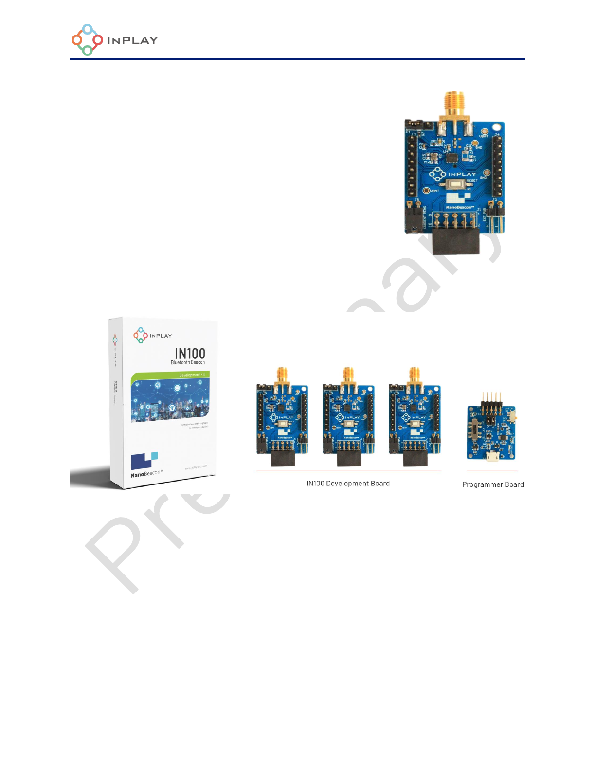
1. General Description
IN1BN-DKC0-100-C0 is an InPlay NanoBeaconTM development kit that
includes 3 IN100 evaluation boards and a programming board.
The development kit provides all the I/Os available on IN100 (QFN18
package) that allow users to easily connect peripheral devices such as
sensors, and by connecting the RF cables using SMA, users can
evaluate the RF performance more accurately. In addition, an external
power supply can be selected to provide a wide range of voltages for
the IN100 product or system evaluation.
A kit contains three development boards and one programmer board.
Figure 1:Development Kit

5 / 10
InPlay NanoBeacon™ IN100 Development Kit User Manual
Development Board
⚫NanoBeaconTM IN100 SoC chipset
⚫SMA Connector
⚫System current measurement jumper
⚫Power supply source selection: Coin Battery /
External power supply / Programmer board
Programmer Board
⚫OTP power switch
⚫1.8V / 3.3V / No connect as power supply option for the
Development Board
⚫OTP memory (eFuse) burning indicator
Figure 2:Development Board
Figure 3:Programmer Board
6 / 10
InPlay NanoBeacon™ IN100 Development Kit User Manual
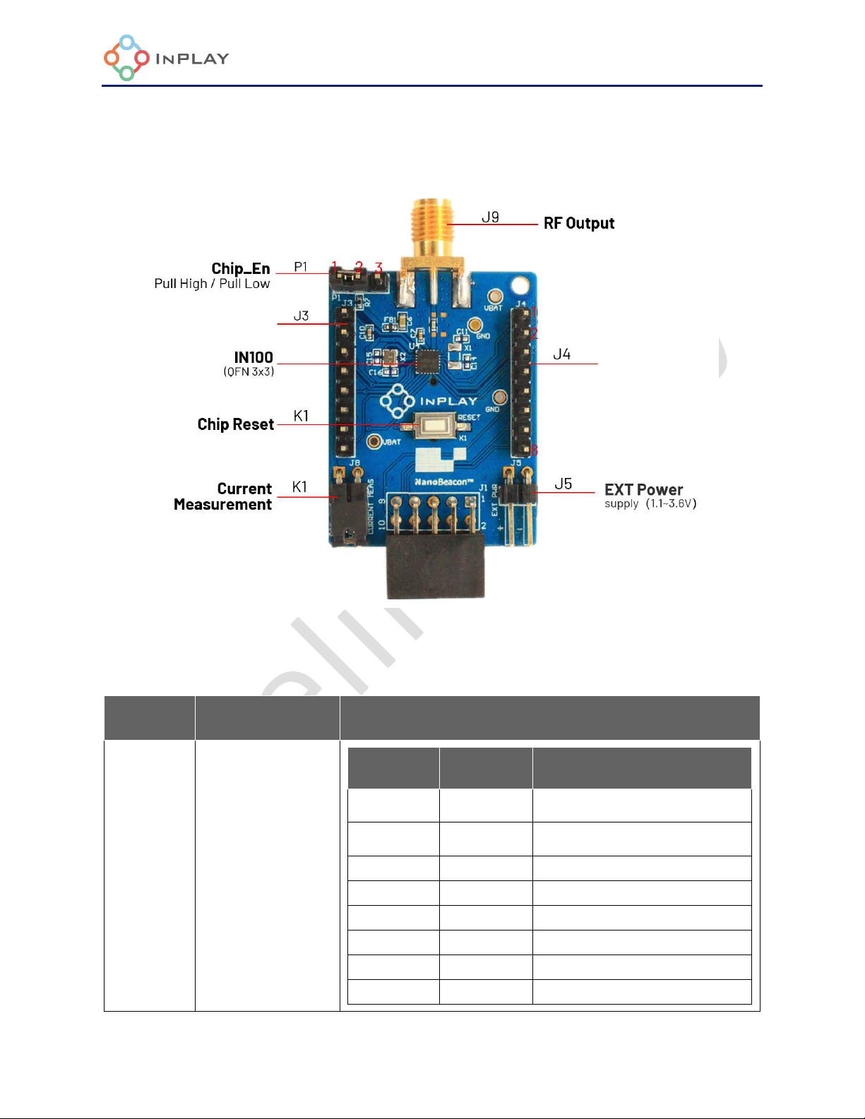
2. Hardware Description
Figure 4:Programmer Board
Development board Key Connectors Definition
Designator
Function
Description
J3
Connector for IOs
and power
Pin number
Pin name
Description
1
Reset
Connect to IN100 Chip_En pin, Pull low to
disable the chip, Pull up to enable the chip
2
VBAT
System power supply, connect to IN100 VCC
pin
3
MGPIO7
IN100 MIX signal GPIO
4
MGPIO6
IN100 MIX signal GPIO
5
MGPIO5
IN100 MIX signal GPIO
6
GND
Power ground
7
SW0
IN100 IO power switch
8
SW1
IN100 IO ground switch
7 / 10
InPlay NanoBeacon™ IN100 Development Kit User Manual
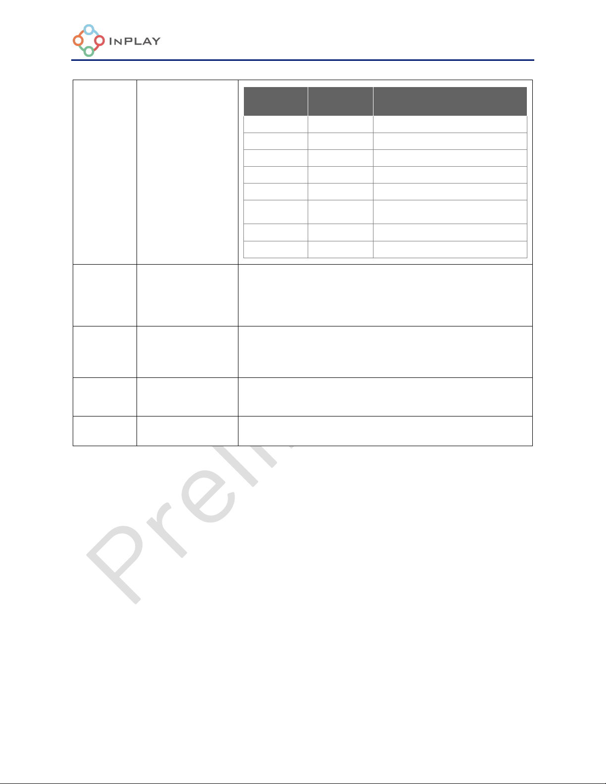
J4
Connector for IOs
and power
Pin number
Pin name
Description
1
VDDQ
OTP (eFuse) programming voltage supply
2
MGPIO4
IN100 MIX signal GPIO
3
GPIO3
IN100 digital signal GPIO
4
GPIO2
IN100 digital signal GPIO
5
GND
Power ground
6
VBAT
System power supply, connect to IN100 VCC
pin
7
GPIO0
IN100 digital GPIO, Default is IN100 UART_RX
8
GPIO1
IN100 digital GPIO, Default is IN100 UART_TX
J5
External power
supply
External Power supply 1.1~3.6V input.
When have this power supply, please keep coin battery not
installed,and Programmer board SW1 switched to OFF
J8
Current
measurement
- for normal operation, jumper needs to be installed
- for current measurement, remove the jumper and have
ammeter connect to pin 1 and pin 2
P1
Chip_En
- active pull-up Chip_EN pin: connect pin 1 and 2
- disable pull-down Chip_EN pin: connect pin 2 and 3
K1
Chip Reset
Chip reset

8 / 10
InPlay NanoBeacon™ IN100 Development Kit User Manual
Figure 5:Programmer Board
Key Connectors Definition
Designator
Function
Description
J6,J7
PC UART Jumpers
Disconnect UART between IN100 and PC when jumper not
installed
J10
Uart Interface
UART for external PC
S1
OTP ON/OFF
-On: eFuse programming, J2 pin2(FUSE) output 3.3V and
connect to IN100 VDDQ.
- OFF: J2 pin2(FUSE) will grounding and connect to IN100
VDDQ
SW1
Voltage Output
-1.8V: 1.8V output for development board;
-3.3V: 3.3V output for development board;
-OFF: No power supply by programmer, supplied by
development board itself.

9 / 10
InPlay NanoBeacon™ IN100 Development Kit User Manual
3. Schematic
Figure 6:Development Kit Schematic

10 / 10
InPlay NanoBeacon™ IN100 Development Kit User Manual
4. Revision History
Revision
Description
Update Date
Owner
V1.0
Preliminary Version
Nov 16, 2021
Eric. Xu
5. Legal Disclaimer
InPlay has made every attempt to ensure the accuracy and reliability of the information provided
on this document. However, the information is provided “as is” without warranty of any kind. The
content of the document will subject to change without prior notice. InPlay does not accept any
responsibility or liability for the accuracy, content, completeness, legally, or reliability of the
information contained on this document. We shall not be liable for any loss or damage of whatever
nature (direct, indirect, consequential or other) whether arising in contract or otherwise, which
may arise as a result of your use of (or inability to use) this document, or from your use of (or failure
to use) the information on this document. InPlay Inc and its company logo are registered
trademarks of InPlay Inc with its registered office at 1 Technology Drive, STE J728, Irvine, CA, USA
92618.
Table of contents
Other InPlay Microcontroller manuals
Popular Microcontroller manuals by other brands

Smarti
Smarti DIS-4X-INTAS Installation & operation manual

Texas Instruments
Texas Instruments TMS320F28069 manual

Renesas
Renesas VENUS user manual

Nordic Semiconductor
Nordic Semiconductor nRF52 Preview Development Kit user guide

sparkfun
sparkfun RFID Starter Kit HOOK-UP GUIDE

Cmsemicon
Cmsemicon CMS32L051 user manual

Nordic Semiconductor
Nordic Semiconductor nRF52 DK user guide

NXP Semiconductors
NXP Semiconductors WB10-AT i.MX 8M user guide

Sierra Wireless
Sierra Wireless mangOH Red HL78 Series Getting started guide

Beninca
Beninca DA.24B2 operating instructions

Texas Instruments
Texas Instruments TAS6584-Q1 EVM user guide

HOLT
HOLT HI-35850 user guide


