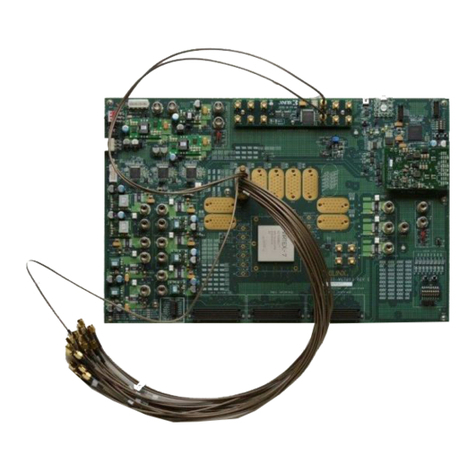
Xilinx ML410 User manual

ML410 Embedded Development Platform www.xilinx.com UG085 (v1.7.2) December 11, 2008
Xilinx is disclosing this user guide, manual, release note, and/or specification (the "Documentation") to you solely for use in the development
of designs to operate with Xilinx hardware devices. You may not reproduce, distribute, republish, download, display, post, or transmit the
Documentation in any form or by any means including, but not limited to, electronic, mechanical, photocopying, recording, or otherwise,
without the prior written consent of Xilinx. Xilinx expressly disclaims any liability arising out of your use of the Documentation. Xilinx reserves
the right, at its sole discretion, to change the Documentation without notice at any time. Xilinx assumes no obligation to correct any errors
contained in the Documentation, or to advise you of any corrections or updates. Xilinx expressly disclaims any liability in connection with
technical support or assistance that may be provided to you in connection with the Information.
THE DOCUMENTATION IS DISCLOSED TO YOU “AS-IS” WITH NO WARRANTY OF ANY KIND. XILINX MAKES NO OTHER
WARRANTIES, WHETHER EXPRESS, IMPLIED, OR STATUTORY, REGARDING THE DOCUMENTATION, INCLUDING ANY
WARRANTIES OF MERCHANTABILITY, FITNESS FOR A PARTICULAR PURPOSE, OR NONINFRINGEMENT OF THIRD-PARTY
RIGHTS. IN NO EVENT WILL XILINX BE LIABLE FOR ANY CONSEQUENTIAL, INDIRECT, EXEMPLARY, SPECIAL, OR INCIDENTAL
DAMAGES, INCLUDING ANY LOSS OF DATA OR LOST PROFITS, ARISING FROM YOUR USE OF THE DOCUMENTATION.
© 2006–2008 Xilinx, Inc. All rights reserved.
XILINX, the Xilinx logo, the Brand Window, and other designated brands included herein are trademarks of Xilinx, Inc. PowerPC is a
trademark of IBM Corp. and is used under license. PCI, PCI-SIG, PCI EXPRESS, PCIE, PCI-X, PCI HOT PLUG, MINI PCI,
EXPRESSMODULE, and the PCI, PCI-X, PCI HOT PLUG, and MINI PC design marks are trademarks, registered trademarks, and/or
service marks of PCI-SIG. All other trademarks are the property of their respective owners.
Revision History
The following table shows the revision history for this document.
Date Version Revision
01/06/06 1.0 Initial Xilinx release.
02/10/06 1.1 Corrected pinouts in Table 2-20, page 53.
05/26/06 1.2 Corrected pinouts in Table 2-5, page 33 and Table 2-21, page 54. Expanded “PCI
Express” section.
09/25/06 1.2.1 Updated PHY address in Table 2-7, page 38 and Table 2-9, page 41. Miscellaneous
typographical edits.
10/26/06 1.3 Updated “Clock Generation,” page 26, “Serial ATA,” page 73, and “High-Speed I/O,”
page 84 for RoHS-compliant revision E boards. Added Appendix A, “Board Revisions.”
11/01/06 1.4 Corrected Table 2-19, page 51.
12/22/06 1.5 Added note to “RocketIO Transceivers,” page 17. Added board revision details to
Table A-1, page 97.
03/06/07 1.6 Updated Table 2-19, page 51 and Table A-1, page 97.
04/06/07 1.6.1 Fixed typo in Figure 2-19, page 71.
09/28/07 1.7 Corrected pinouts in Table 2-15, page 46 for SYSACE_FPGA_CLK, SYSACE_MPD[15],
SYSACE_MPCE, and SYSACE_MPWE signals.
03/05/08 1.7.1 Fixed typo in Table 2-8, page 40. Updated trademark statements and copyright date.
12/11/08 1.7.2 Minor edits to Table A-1, page 97. Removed support for unbuffered DIMMs.
R
Downloaded from Elcodis.com electronic components distributor

ML410 Embedded Development Platform www.xilinx.com 3
UG085 (v1.7.2) December 11, 2008
Schedule of Figures. . . . . . . . . . . . . . . . . . . . . . . . . . . . . . . . . . . . . . . . . . . . . . . . . . . . . . . . . . 7
Schedule of Tables . . . . . . . . . . . . . . . . . . . . . . . . . . . . . . . . . . . . . . . . . . . . . . . . . . . . . . . . . . . 9
Preface: About This Guide
Additional Resources . . . . . . . . . . . . . . . . . . . . . . . . . . . . . . . . . . . . . . . . . . . . . . . . . . . . . . . 11
Conventions . . . . . . . . . . . . . . . . . . . . . . . . . . . . . . . . . . . . . . . . . . . . . . . . . . . . . . . . . . . . . . . . 11
Typographical. . . . . . . . . . . . . . . . . . . . . . . . . . . . . . . . . . . . . . . . . . . . . . . . . . . . . . . . . . . . 11
Online Document . . . . . . . . . . . . . . . . . . . . . . . . . . . . . . . . . . . . . . . . . . . . . . . . . . . . . . . . . 12
Chapter 1: Introduction to Virtex-4, ISE, and EDK
Virtex-4 FPGAs . . . . . . . . . . . . . . . . . . . . . . . . . . . . . . . . . . . . . . . . . . . . . . . . . . . . . . . . . . . . . 15
Summary of Virtex-4 FX Features . . . . . . . . . . . . . . . . . . . . . . . . . . . . . . . . . . . . . . . . . . . 15
PowerPC™ 405 Core . . . . . . . . . . . . . . . . . . . . . . . . . . . . . . . . . . . . . . . . . . . . . . . . . . . . . . 16
RocketIO Transceivers. . . . . . . . . . . . . . . . . . . . . . . . . . . . . . . . . . . . . . . . . . . . . . . . . . . . . 17
ISE Foundation . . . . . . . . . . . . . . . . . . . . . . . . . . . . . . . . . . . . . . . . . . . . . . . . . . . . . . . . . . . . . 17
Foundation Features . . . . . . . . . . . . . . . . . . . . . . . . . . . . . . . . . . . . . . . . . . . . . . . . . . . . . . 17
Design Entry . . . . . . . . . . . . . . . . . . . . . . . . . . . . . . . . . . . . . . . . . . . . . . . . . . . . . . . . . . 17
Synthesis . . . . . . . . . . . . . . . . . . . . . . . . . . . . . . . . . . . . . . . . . . . . . . . . . . . . . . . . . . . . . 18
Implementation and Configuration . . . . . . . . . . . . . . . . . . . . . . . . . . . . . . . . . . . . . . . . 18
Board-Level Integration . . . . . . . . . . . . . . . . . . . . . . . . . . . . . . . . . . . . . . . . . . . . . . . . . 18
Embedded Development Kit . . . . . . . . . . . . . . . . . . . . . . . . . . . . . . . . . . . . . . . . . . . . . . . . 19
EDK Components . . . . . . . . . . . . . . . . . . . . . . . . . . . . . . . . . . . . . . . . . . . . . . . . . . . . . . . . 19
Platform Studio Features . . . . . . . . . . . . . . . . . . . . . . . . . . . . . . . . . . . . . . . . . . . . . . . . . . 19
Chapter 2: ML410 Embedded Development Platform
Overview . . . . . . . . . . . . . . . . . . . . . . . . . . . . . . . . . . . . . . . . . . . . . . . . . . . . . . . . . . . . . . . . . . . 21
Features . . . . . . . . . . . . . . . . . . . . . . . . . . . . . . . . . . . . . . . . . . . . . . . . . . . . . . . . . . . . . . . . . 21
Block Diagram . . . . . . . . . . . . . . . . . . . . . . . . . . . . . . . . . . . . . . . . . . . . . . . . . . . . . . . . . . . 23
Related Xilinx Documents. . . . . . . . . . . . . . . . . . . . . . . . . . . . . . . . . . . . . . . . . . . . . . . . . . . 23
Detailed Description . . . . . . . . . . . . . . . . . . . . . . . . . . . . . . . . . . . . . . . . . . . . . . . . . . . . . . . . 24
Configuration . . . . . . . . . . . . . . . . . . . . . . . . . . . . . . . . . . . . . . . . . . . . . . . . . . . . . . . . . . . . 25
I/O Voltage Rails . . . . . . . . . . . . . . . . . . . . . . . . . . . . . . . . . . . . . . . . . . . . . . . . . . . . . . . . . 25
Digitally Controlled Impedance (DCI) . . . . . . . . . . . . . . . . . . . . . . . . . . . . . . . . . . . . . . . 25
Clock Generation . . . . . . . . . . . . . . . . . . . . . . . . . . . . . . . . . . . . . . . . . . . . . . . . . . . . . . . . . 26
DDR and DDR2 Memory . . . . . . . . . . . . . . . . . . . . . . . . . . . . . . . . . . . . . . . . . . . . . . . . . . 29
DDR Component Memory . . . . . . . . . . . . . . . . . . . . . . . . . . . . . . . . . . . . . . . . . . . . . . . 29
DDR2 SDRAM DIMM . . . . . . . . . . . . . . . . . . . . . . . . . . . . . . . . . . . . . . . . . . . . . . . . . . 32
Tri-Mode (10/100/1000 Mb/s) Ethernet PHY. . . . . . . . . . . . . . . . . . . . . . . . . . . . . . . . . 37
PHY0: MII/RGMII . . . . . . . . . . . . . . . . . . . . . . . . . . . . . . . . . . . . . . . . . . . . . . . . . . . . . 38
PHY1: SGMII . . . . . . . . . . . . . . . . . . . . . . . . . . . . . . . . . . . . . . . . . . . . . . . . . . . . . . . . . 41
RS-232 Ports . . . . . . . . . . . . . . . . . . . . . . . . . . . . . . . . . . . . . . . . . . . . . . . . . . . . . . . . . . 43
System ACE CF Controller . . . . . . . . . . . . . . . . . . . . . . . . . . . . . . . . . . . . . . . . . . . . . . . . . 44
Introduction to JTAG . . . . . . . . . . . . . . . . . . . . . . . . . . . . . . . . . . . . . . . . . . . . . . . . . . . 44
Table of Contents
Downloaded from Elcodis.com electronic components distributor

4www.xilinx.com ML410 Embedded Development Platform
UG085 (v1.7.2) December 11, 2008
R
Introduction to the System ACE Configuration Solution . . . . . . . . . . . . . . . . . . . . . . . . 44
Board Bring-Up through the JTAG Interface . . . . . . . . . . . . . . . . . . . . . . . . . . . . . . . . . 45
Non-Volatile Storage through the MPU Interface. . . . . . . . . . . . . . . . . . . . . . . . . . . . . . 46
GPIO LEDs and LCD . . . . . . . . . . . . . . . . . . . . . . . . . . . . . . . . . . . . . . . . . . . . . . . . . . . . . . 47
GPIO LED Interface . . . . . . . . . . . . . . . . . . . . . . . . . . . . . . . . . . . . . . . . . . . . . . . . . . . . 49
GPIO LCD Interface . . . . . . . . . . . . . . . . . . . . . . . . . . . . . . . . . . . . . . . . . . . . . . . . . . . . 49
CPU Debugging Interfaces . . . . . . . . . . . . . . . . . . . . . . . . . . . . . . . . . . . . . . . . . . . . . . . . . 50
CPU Debug Description . . . . . . . . . . . . . . . . . . . . . . . . . . . . . . . . . . . . . . . . . . . . . . . . . 50
CPU JTAG Header Pinout . . . . . . . . . . . . . . . . . . . . . . . . . . . . . . . . . . . . . . . . . . . . . . . 53
CPU JTAG Connection to FPGA. . . . . . . . . . . . . . . . . . . . . . . . . . . . . . . . . . . . . . . . . . . 53
VGA Output . . . . . . . . . . . . . . . . . . . . . . . . . . . . . . . . . . . . . . . . . . . . . . . . . . . . . . . . . . . . . 54
PCI Express . . . . . . . . . . . . . . . . . . . . . . . . . . . . . . . . . . . . . . . . . . . . . . . . . . . . . . . . . . . . . . 55
PCI Bus . . . . . . . . . . . . . . . . . . . . . . . . . . . . . . . . . . . . . . . . . . . . . . . . . . . . . . . . . . . . . . . . . 57
ALi South Bridge Interface, M1535D+ (U15) . . . . . . . . . . . . . . . . . . . . . . . . . . . . . . . . . . 62
Parallel Port Interface Connector Assembly (P1) . . . . . . . . . . . . . . . . . . . . . . . . . . . . . . 63
USB Connector Assembly (J3). . . . . . . . . . . . . . . . . . . . . . . . . . . . . . . . . . . . . . . . . . . . . 63
IDE Connectors (J15 and J16) . . . . . . . . . . . . . . . . . . . . . . . . . . . . . . . . . . . . . . . . . . . . . 64
GPIO Connector (J5) . . . . . . . . . . . . . . . . . . . . . . . . . . . . . . . . . . . . . . . . . . . . . . . . . . . . 66
System Management Bus Controller. . . . . . . . . . . . . . . . . . . . . . . . . . . . . . . . . . . . . . . . 66
AC’97 Audio Interface . . . . . . . . . . . . . . . . . . . . . . . . . . . . . . . . . . . . . . . . . . . . . . . . . . 67
PS/2 Keyboard and Mouse Interface Connector (P2) . . . . . . . . . . . . . . . . . . . . . . . . . . . 68
Flash ROM (U4) . . . . . . . . . . . . . . . . . . . . . . . . . . . . . . . . . . . . . . . . . . . . . . . . . . . . . . . 68
IIC/SMBus Interface . . . . . . . . . . . . . . . . . . . . . . . . . . . . . . . . . . . . . . . . . . . . . . . . . . . . . . 69
Introduction to IIC/SMBus. . . . . . . . . . . . . . . . . . . . . . . . . . . . . . . . . . . . . . . . . . . . . . . 69
IIC/SMBus Signaling . . . . . . . . . . . . . . . . . . . . . . . . . . . . . . . . . . . . . . . . . . . . . . . . . . . 69
IIC/SMBus on ML410 Platforms. . . . . . . . . . . . . . . . . . . . . . . . . . . . . . . . . . . . . . . . . . . 70
Serial Peripheral Interface. . . . . . . . . . . . . . . . . . . . . . . . . . . . . . . . . . . . . . . . . . . . . . . . . . 72
SPI Signaling . . . . . . . . . . . . . . . . . . . . . . . . . . . . . . . . . . . . . . . . . . . . . . . . . . . . . . . . . . 72
SPI Addressing . . . . . . . . . . . . . . . . . . . . . . . . . . . . . . . . . . . . . . . . . . . . . . . . . . . . . . . . 73
Serial ATA . . . . . . . . . . . . . . . . . . . . . . . . . . . . . . . . . . . . . . . . . . . . . . . . . . . . . . . . . . . . . . . 73
Serial ATA Description . . . . . . . . . . . . . . . . . . . . . . . . . . . . . . . . . . . . . . . . . . . . . . . . . . 73
FPGA to Serial ATA Connector . . . . . . . . . . . . . . . . . . . . . . . . . . . . . . . . . . . . . . . . . . . 73
Pushbuttons, Switches, Front Panel Interface, and Jumpers . . . . . . . . . . . . . . . . . . . . . 74
Pushbuttons . . . . . . . . . . . . . . . . . . . . . . . . . . . . . . . . . . . . . . . . . . . . . . . . . . . . . . . . . . 74
Switches . . . . . . . . . . . . . . . . . . . . . . . . . . . . . . . . . . . . . . . . . . . . . . . . . . . . . . . . . . . . . 75
Front Panel Interface (J23). . . . . . . . . . . . . . . . . . . . . . . . . . . . . . . . . . . . . . . . . . . . . . . . 77
Jumpers. . . . . . . . . . . . . . . . . . . . . . . . . . . . . . . . . . . . . . . . . . . . . . . . . . . . . . . . . . . . . . 79
ATX Power Distribution and Voltage Regulation . . . . . . . . . . . . . . . . . . . . . . . . . . . . . 80
High-Speed I/O . . . . . . . . . . . . . . . . . . . . . . . . . . . . . . . . . . . . . . . . . . . . . . . . . . . . . . . . . . . . . 84
Personality Module Connectors. . . . . . . . . . . . . . . . . . . . . . . . . . . . . . . . . . . . . . . . . . . . . 85
Z-Dok+ Connector Offsets . . . . . . . . . . . . . . . . . . . . . . . . . . . . . . . . . . . . . . . . . . . . . . . 85
PM1 Connector . . . . . . . . . . . . . . . . . . . . . . . . . . . . . . . . . . . . . . . . . . . . . . . . . . . . . . . . 86
PM2 Connector . . . . . . . . . . . . . . . . . . . . . . . . . . . . . . . . . . . . . . . . . . . . . . . . . . . . . . . . 86
Adapter Board PM Connectors. . . . . . . . . . . . . . . . . . . . . . . . . . . . . . . . . . . . . . . . . . . . 86
Z-DOK+ Utility Pins . . . . . . . . . . . . . . . . . . . . . . . . . . . . . . . . . . . . . . . . . . . . . . . . . . . . . . 87
Contact Order . . . . . . . . . . . . . . . . . . . . . . . . . . . . . . . . . . . . . . . . . . . . . . . . . . . . . . . . . 88
PM1 Power and Ground . . . . . . . . . . . . . . . . . . . . . . . . . . . . . . . . . . . . . . . . . . . . . . . . . 88
PM User I/O Pins. . . . . . . . . . . . . . . . . . . . . . . . . . . . . . . . . . . . . . . . . . . . . . . . . . . . . . . . . 89
PM1 User I/O . . . . . . . . . . . . . . . . . . . . . . . . . . . . . . . . . . . . . . . . . . . . . . . . . . . . . . . . . 89
PM2 User I/O . . . . . . . . . . . . . . . . . . . . . . . . . . . . . . . . . . . . . . . . . . . . . . . . . . . . . . . . . 91
Downloaded from Elcodis.com electronic components distributor


ML410 Embedded Development Platform www.xilinx.com 7
UG085 (v1.7.2) December 11, 2008
Chapter 1: Introduction to Virtex-4, ISE, and EDK
Chapter 2: ML410 Embedded Development Platform
Figure 2-1: ML410 High-Level Block Diagram . . . . . . . . . . . . . . . . . . . . . . . . . . . . . . . . . . . . 23
Figure 2-2: ML410 Board and Front Panel Detail . . . . . . . . . . . . . . . . . . . . . . . . . . . . . . . . . . 24
Figure 2-3: ML410 Clock Distribution . . . . . . . . . . . . . . . . . . . . . . . . . . . . . . . . . . . . . . . . . . . 27
Figure 2-4: DDR Component Block Diagram . . . . . . . . . . . . . . . . . . . . . . . . . . . . . . . . . . . . . 29
Figure 2-5: DDR2 DIMM Block Diagram . . . . . . . . . . . . . . . . . . . . . . . . . . . . . . . . . . . . . . . . 37
Figure 2-6: PHY0 Jumper (J28) Settings . . . . . . . . . . . . . . . . . . . . . . . . . . . . . . . . . . . . . . . . . . 38
Figure 2-7: MII Interface . . . . . . . . . . . . . . . . . . . . . . . . . . . . . . . . . . . . . . . . . . . . . . . . . . . . . . . 39
Figure 2-8: RGMII Interface . . . . . . . . . . . . . . . . . . . . . . . . . . . . . . . . . . . . . . . . . . . . . . . . . . . . 39
Figure 2-9: SGMII Interface . . . . . . . . . . . . . . . . . . . . . . . . . . . . . . . . . . . . . . . . . . . . . . . . . . . . 42
Figure 2-10: FPGA UART and RS-232 Connectivity . . . . . . . . . . . . . . . . . . . . . . . . . . . . . . . 43
Figure 2-11: JTAG Connections to the FPGA and System ACE CF Controller . . . . . . . . 45
Figure 2-12: PC4 JTAG Connector Pinout (J9) . . . . . . . . . . . . . . . . . . . . . . . . . . . . . . . . . . . . 46
Figure 2-13: LEDs and LCD Connectivity . . . . . . . . . . . . . . . . . . . . . . . . . . . . . . . . . . . . . . . . 48
Figure 2-14: Combined Trace/Debug Connector Pinout. . . . . . . . . . . . . . . . . . . . . . . . . . . . 51
Figure 2-15: CPU JTAG Header (J12) . . . . . . . . . . . . . . . . . . . . . . . . . . . . . . . . . . . . . . . . . . . . 53
Figure 2-16: PCI Express Power Management and Clocking. . . . . . . . . . . . . . . . . . . . . . . . 55
Figure 2-17: PCI Bus and Device Connectivity. . . . . . . . . . . . . . . . . . . . . . . . . . . . . . . . . . . . 58
Figure 2-18: ALi South Bridge Interface, M1535D+ (U15) . . . . . . . . . . . . . . . . . . . . . . . . . . 62
Figure 2-19: IIC and SMBus Block Diagram . . . . . . . . . . . . . . . . . . . . . . . . . . . . . . . . . . . . . . 71
Figure 2-20: SPI EEPROM Device Interface . . . . . . . . . . . . . . . . . . . . . . . . . . . . . . . . . . . . . . 73
Figure 2-21: SW3: System ACE Configuration Switch Detail . . . . . . . . . . . . . . . . . . . . . . . 76
Figure 2-22: ATX Power Distribution and Voltage Regulation . . . . . . . . . . . . . . . . . . . . . 81
Figure 2-23: Voltage Monitors . . . . . . . . . . . . . . . . . . . . . . . . . . . . . . . . . . . . . . . . . . . . . . . . . . 82
Figure 2-24: Personality Module Connected to Embedded Development Platform. . . . 84
Figure 2-25: Edge View of Host Board Connectors . . . . . . . . . . . . . . . . . . . . . . . . . . . . . . . . 85
Figure 2-26: Host Board Connector Pin Detail . . . . . . . . . . . . . . . . . . . . . . . . . . . . . . . . . . . . 85
Figure 2-27: Adapter Board Connector Pin Detail . . . . . . . . . . . . . . . . . . . . . . . . . . . . . . . . . 87
Figure 2-28: Z-DOK+ Utility Pins (ML410 Side) . . . . . . . . . . . . . . . . . . . . . . . . . . . . . . . . . . 87
Figure 2-29: Z-DOK+ Utility Pins (Adapter Side) . . . . . . . . . . . . . . . . . . . . . . . . . . . . . . . . . 88
Appendix A: Board Revisions
Figure A-1: Clock Distribution for Revisions C and D. . . . . . . . . . . . . . . . . . . . . . . . . . . . . 98
Appendix B: References
Schedule of Figures
Downloaded from Elcodis.com electronic components distributor
ML410 Embedded Development Platform www.xilinx.com 9
UG085 (v1.7.2) December 11, 2008
Chapter 1: Introduction to Virtex-4, ISE, and EDK
Table 1-1: Virtex-4 FX Family Members. . . . . . . . . . . . . . . . . . . . . . . . . . . . . . . . . . . . . . . . . . 16
Chapter 2: ML410 Embedded Development Platform
Table 2-1: I/O Voltage Rail of FPGA Banks. . . . . . . . . . . . . . . . . . . . . . . . . . . . . . . . . . . . . . . 25
Table 2-2: DCI Capability of FPGA Bank . . . . . . . . . . . . . . . . . . . . . . . . . . . . . . . . . . . . . . . . 25
Table 2-3: Clock Connections . . . . . . . . . . . . . . . . . . . . . . . . . . . . . . . . . . . . . . . . . . . . . . . . . . . 28
Table 2-4: Connections from FPGA to DDR1 SDRAMs (U42 and U43) . . . . . . . . . . . . . . 30
Table 2-5: Connections from FPGA to DDR2 DIMM Interface (P48) . . . . . . . . . . . . . . . . 33
Table 2-6: Marvell Alaska PHY Configurations . . . . . . . . . . . . . . . . . . . . . . . . . . . . . . . . . . . 37
Table 2-7: PHY0 (U60) Configuration Settings for MII/RGMII. . . . . . . . . . . . . . . . . . . . . . 38
Table 2-8: PHY0 MII/RGMII Interface . . . . . . . . . . . . . . . . . . . . . . . . . . . . . . . . . . . . . . . . . . . 40
Table 2-9: PHY1 (U61) Configuration Settings for SGMII . . . . . . . . . . . . . . . . . . . . . . . . . . 41
Table 2-10: PHY1 SGMII Interface . . . . . . . . . . . . . . . . . . . . . . . . . . . . . . . . . . . . . . . . . . . . . . 41
Table 2-11: PHY1 MDIO Interface. . . . . . . . . . . . . . . . . . . . . . . . . . . . . . . . . . . . . . . . . . . . . . . 41
Table 2-12: FPGA RS-232 Connections for UART0 . . . . . . . . . . . . . . . . . . . . . . . . . . . . . . . . 43
Table 2-13: FPGA RS-232 Connections for UART1 . . . . . . . . . . . . . . . . . . . . . . . . . . . . . . . . 44
Table 2-14: JTAG Connection from System ACE CF to FPGA . . . . . . . . . . . . . . . . . . . . . . 46
Table 2-15: System ACE MPU Connection from FPGA to Controller . . . . . . . . . . . . . . . . 46
Table 2-16: GPIO LED Connection from FPGA to U36. . . . . . . . . . . . . . . . . . . . . . . . . . . . . 49
Table 2-17: GPIO LCD Data Signals from FPGA to U35 . . . . . . . . . . . . . . . . . . . . . . . . . . . 49
Table 2-18: GPIO LCD Control Signals from FPGA to U33 . . . . . . . . . . . . . . . . . . . . . . . . . 50
Table 2-19: CPU Trace/Debug Connection to FPGA . . . . . . . . . . . . . . . . . . . . . . . . . . . . . . . 51
Table 2-20: CPU JTAG Connection to FPGA. . . . . . . . . . . . . . . . . . . . . . . . . . . . . . . . . . . . . . 53
Table 2-21: Connections from FPGA to DAC . . . . . . . . . . . . . . . . . . . . . . . . . . . . . . . . . . . . . 54
Table 2-22: Connections from FPGA to PCI Express Slot A. . . . . . . . . . . . . . . . . . . . . . . . . 56
Table 2-23: Connections from FPGA to PCI Express Slot B . . . . . . . . . . . . . . . . . . . . . . . . . 57
Table 2-24: PCI Controller Connections. . . . . . . . . . . . . . . . . . . . . . . . . . . . . . . . . . . . . . . . . . 59
Table 2-25: 3.3V Primary PCI Bus Information. . . . . . . . . . . . . . . . . . . . . . . . . . . . . . . . . . . . 61
Table 2-26: 5V Secondary PCI Bus Information . . . . . . . . . . . . . . . . . . . . . . . . . . . . . . . . . . . 61
Table 2-27: ALi South Bridge Parallel Port Connections . . . . . . . . . . . . . . . . . . . . . . . . . . . 63
Table 2-28: ALi South Bridge Connections to USB Type-A . . . . . . . . . . . . . . . . . . . . . . . . . 64
Table 2-29: ALi South Bridge IDE Connections . . . . . . . . . . . . . . . . . . . . . . . . . . . . . . . . . . . 64
Table 2-30: Type of GPIO Available on Header J5 . . . . . . . . . . . . . . . . . . . . . . . . . . . . . . . . 66
Table 2-31: GPIO Connections on Header J5 . . . . . . . . . . . . . . . . . . . . . . . . . . . . . . . . . . . . . 66
Table 2-32: Audio Jacks (J1, J2, and J31) . . . . . . . . . . . . . . . . . . . . . . . . . . . . . . . . . . . . . . . . . . 67
Table 2-33: PS/2 Keyboard and Mouse . . . . . . . . . . . . . . . . . . . . . . . . . . . . . . . . . . . . . . . . . . . 68
Table 2-34: ALi M1535D+ Flash Memory Interface . . . . . . . . . . . . . . . . . . . . . . . . . . . . . . . . 68
Schedule of Tables
Downloaded from Elcodis.com electronic components distributor
10 www.xilinx.com ML410 Embedded Development Platform
UG085 (v1.7.2) December 11, 2008
R
Table 2-35: IIC and SMBus Controller Connections . . . . . . . . . . . . . . . . . . . . . . . . . . . . . . . 70
Table 2-36: IIC Devices and Addresses . . . . . . . . . . . . . . . . . . . . . . . . . . . . . . . . . . . . . . . . . . 72
Table 2-37: IIC and SMBus Controller Connections . . . . . . . . . . . . . . . . . . . . . . . . . . . . . . . 73
Table 2-38: Connections Between FPGA and Serial ATA Connector (J25 and J26). . . . . 74
Table 2-39: SW6 Output. . . . . . . . . . . . . . . . . . . . . . . . . . . . . . . . . . . . . . . . . . . . . . . . . . . . . . . . 76
Table 2-40: Outputs of the Clock Multiplexer (U6) . . . . . . . . . . . . . . . . . . . . . . . . . . . . . . . . 77
Table 2-41: Front Panel Interface Connector (J23) . . . . . . . . . . . . . . . . . . . . . . . . . . . . . . . . . 78
Table 2-42: 5V Fan BERG Header Connections . . . . . . . . . . . . . . . . . . . . . . . . . . . . . . . . . . . 79
Table 2-43: Voltage Margining Jumper Settings . . . . . . . . . . . . . . . . . . . . . . . . . . . . . . . . . . 80
Table 2-44: Voltage Monitor Information . . . . . . . . . . . . . . . . . . . . . . . . . . . . . . . . . . . . . . . . 83
Table 2-45: Delay Offsets . . . . . . . . . . . . . . . . . . . . . . . . . . . . . . . . . . . . . . . . . . . . . . . . . . . . . . 85
Table 2-46: Relative Offsets from the FPGA to the PM1 and PM2 Connectors . . . . . . . . 86
Table 2-47: PM1 Power and Ground Pins . . . . . . . . . . . . . . . . . . . . . . . . . . . . . . . . . . . . . . . . 88
Table 2-48: PM1 Pinout . . . . . . . . . . . . . . . . . . . . . . . . . . . . . . . . . . . . . . . . . . . . . . . . . . . . . . . . 89
Table 2-49: PM2 Pinout . . . . . . . . . . . . . . . . . . . . . . . . . . . . . . . . . . . . . . . . . . . . . . . . . . . . . . . . 91
Appendix A: Board Revisions
Table A-1: Platforms, Devices, and Features . . . . . . . . . . . . . . . . . . . . . . . . . . . . . . . . . . . . . . 97
Table A-2: MGT and SATA Clock Connections for Revisions C and D . . . . . . . . . . . . . . 99
Appendix B: References
Downloaded from Elcodis.com electronic components distributor
ML410 Embedded Development Platform www.xilinx.com 11
UG085 (v1.7.2) December 11, 2008
R
Preface
About This Guide
This manual accompanies the ML410 series of Embedded Development Platforms and
contains information about the ML410 hardware and software tools.
Guide Contents
This manual contains the following chapters:
•Chapter 1, “Introduction to Virtex-4, ISE, and EDK,” provides an overview of the
hardware and software features
•Chapter 2, “ML410 Embedded Development Platform,” provides an overview of the
embedded development platform and details the components and features of the
ML410 board
•Appendix A, “Board Revisions” details the differences between board revisions in the
ML410 series
•Appendix B, “References”
Additional Resources
To find additional documentation, see the Xilinx® website at:
http://www.xilinx.com/literature.
To search the Answer Database of silicon, software, and IP questions and answers, or to
create a technical support WebCase, see the Xilinx website at:
http://www.xilinx.com/support.
Conventions
This document uses the following conventions. An example illustrates each convention.
Typographical
The following typographical conventions are used in this document:
Downloaded from Elcodis.com electronic components distributor

12 www.xilinx.com ML410 Embedded Development Platform
UG085 (v1.7.2) December 11, 2008
Preface: About This Guide
R
Online Document
The following conventions are used in this document:
Convention Meaning or Use Example
Courier font
Messages, prompts, and
program files that the system
displays
speed grade: - 100
Courier bold Literal commands that you enter
in a syntactical statement ngdbuild design_name
Helvetica bold
Commands that you select from
a menu File →Open
Keyboard shortcuts Ctrl+C
Italic font
Variables in a syntax statement
for which you must supply
values
ngdbuild design_name
References to other manuals
See the Development System
Reference Guide for more
information.
Emphasis in text
If a wire is drawn so that it
overlaps the pin of a symbol, the
two nets are not connected.
Square brackets [ ]
An optional entry or parameter.
However, in bus specifications,
such as bus[7:0], they are
required.
ngdbuild [option_name]
design_name
Braces { } A list of items from which you
must choose one or more lowpwr ={on|off}
Vertical bar | Separates items in a list of
choices lowpwr ={on|off}
Vertical ellipsis
.
.
.
Repetitive material that has
been omitted
IOB #1: Name = QOUT’
IOB #2: Name = CLKIN’
.
.
.
Horizontal ellipsis . . . Repetitive material that has
been omitted
allow block block_name loc1
loc2 ... locn;
Convention Meaning or Use Example
Blue text Cross-reference link to a location
in the current document
See the section “Additional
Resources” for details.
Refer to “Title Formats” in
Chapter 1 for details.
Downloaded from Elcodis.com electronic components distributor
ML410 Embedded Development Platform www.xilinx.com 13
UG085 (v1.7.2) December 11, 2008
Conventions
R
Red text Cross-reference link to a location
in another document
See Figure 2-5 in the Virtex-II
Platform FPGA User Guide.
Blue, underlined text Hyperlink to a website (URL) Go to http://www.xilinx.com
for the latest speed files.
Convention Meaning or Use Example
Downloaded from Elcodis.com electronic components distributor

ML410 Embedded Development Platform www.xilinx.com 15
UG085 (v1.7.2) December 11, 2008
R
Chapter 1
Introduction
to Virtex-4, ISE, and EDK
Virtex-4 FPGAs
Virtex®-4 domain-optimized FPGAs provide an ideal mix of features and the greatest
choice of devices of any FPGA product line on the market today, with a column-based
architecture unique to the programmable logic industry. Virtex-4 FPGAs contain three
platforms: LX, FX, and SX. Choice and feature combinations are offered for all complex
applications. A wide array of hard-IP core blocks complete the system solution. These
cores include the PowerPC® processors (with a new APU interface), Tri-Mode Ethernet
MACs, 622 Mb/s to 6.5 Gb/s serial transceivers, dedicated DSP slices, high-speed clock
management circuitry, and source-synchronous interface blocks. The basic Virtex-4
building blocks allow migration of existing Virtex series designs. Virtex-4 devices are
produced by a state-of-the-art 90 nm copper process, using 300 mm (12 inch) wafer
technology. Combining a wide variety of flexible features, the Virtex-4 family enhances
programmable logic design capabilities and is a powerful alternative to ASIC technology.
Summary of Virtex-4 FX Features
The Virtex-4 family has an impressive collection of both programmable logic and hard IP,
historically the domain of ASICs. The Virtex-4 FX FPGAs used on ML410 platforms are
high-performance, full-featured solutions for embedded platform applications.
•Xesium™ clock technology
♦Digital clock manager (DCM) blocks
♦Additional phase-matched clock dividers (PMCD)
♦Differential global clocks
•XtremeDSP™ slice
♦18 x 18, two’s complement, signed multiplier
♦Optional pipeline stages
♦Built-in accumulator (48-bits) and adder/subtracter
•Smart RAM memory hierarchy
♦Distributed RAM
♦Dual-port 18 Kb RAM blocks
-Optional pipeline stages
-Optional programmable FIFO logic - Automatically remaps RAM signals as
FIFO signals
♦High-speed memory interface support: DDR and DDR2
•SDRAM, QDR II, RLDRAM II, and FCRAM II SelectIO technology
♦1.5V to 3.3V I/O operation
Downloaded from Elcodis.com electronic components distributor

16 www.xilinx.com ML410 Embedded Development Platform
UG085 (v1.7.2) December 11, 2008
Chapter 1: Introduction to Virtex-4, ISE, and EDK
R
♦Built-in ChipSync™ source-synchronous technology
♦Digitally-controlled impedance (DCI) active termination
♦Fine grained I/O banking (configuration in one bank)
•Flexible logic resources
•Secure Chip AES bitstream encryption
•90 nm copper CMOS process
•1.2V core voltage
•Flip-Chip packaging
•RocketIO™ 622 Mb/s to 6.5 Gb/s multi-gigabit transceivers (MGT)
•IBM PowerPC RISC processor core
♦PowerPC 405 (PPC405) core
♦Auxiliary processor unit interface (user coprocessor)
•Multiple Tri-Mode Ethernet MACs
PowerPC™ 405 Core
•32-bit Harvard architecture core
•Five-stage execution pipeline
•Integrated 16 KB level 1 instruction cache and 16 KB level 1 data cache
♦Integrated level 1 cache parity generation and checking
•CoreConnect™ bus architecture
•Efficient, high-performance on-chip memory (OCM) interface to block RAM
•PLB synchronization logic (enables non-integer CPU-to-PLB clock ratios)
•Auxiliary Processor Unit (APU) interface and integrated APU controller
♦Optimized FPGA-based coprocessor connection
♦Automatic decode of PowerPC floating-point instructions
♦Allows custom instructions (decode for up to eight instructions)
♦Extremely efficient microcontroller-style interfacing
Table 1-1: Virtex-4 FX Family Members
Device XC4VFX12 XC4VFX20 XC4VFX40 XC4VFX60 XC4VFX100 XC4VFX140
Logic Cells 12,312 19,224 41,904 56,880 94,896 142,128
PPC405 1 1 2 2 2 2
MGTs N/A 8 12 16 20 24
Block RAM
(Kb) 648 1,224 2,592 4,176 6,768 9,936
XtremeDSP
Multipliers 32 32 48 128 160 192
Downloaded from Elcodis.com electronic components distributor
ML410 Embedded Development Platform www.xilinx.com 17
UG085 (v1.7.2) December 11, 2008
ISE Foundation
R
RocketIO Transceivers
•Full-duplex serial transceiver (SERDES) capable of running 622 Mb/s - 6.5 Gb/s
Note: Only Revision E boards support 6.5 Gb/s. See Appendix A, “Board Revisions” for more
details.
•Full clock and data recovery
•32-bit or 40-bit datapath support
•Optional 8B/10B, 64B/66B, or FPGA-based encode/decode
•Integrated FIFO/elastic buffer
•Support for channel bonding
•Embedded 32-bit CRC generation/checking
•Integrated comma-detect or programmable A1/A2, A1A1/A2A2 detection
•Programmable pre-emphasis (AKA transmitter equalization)
•Programmable receiver equalization
•Embedded support for:
♦Out of band (OOB) signaling: Serial ATA
♦Beaconing and electrical idle: PCI Express®
•On-chip bypassable AC coupling for receiver
ISE Foundation
ISE Foundation is the industry's most complete programmable logic design environment.
With ISE Foundation, you have everything you need to target today’s most advanced
CPLDs and FPGAs, including the new Virtex-4 family of FPGAs. ISE Foundation includes
the industry's most advanced timing driven implementation tools available for
programmable logic design, along with design entry, synthesis and verification
capabilities. With its ultra-fast runtimes, an average 40% faster than the nearest
competitive FPGA offering, ProActive Timing Closure technologies, and seamless
integration with the industry's most advanced verification products, ISE Foundation offers
a great design environment in which to create a complete programmable logic design
solution.
Foundation Features
Design Entry
ISE greatly improves time-to-market, productivity, and design quality with robust design
entry features. ISE provides support for today's most popular methods for design capture
including HDL and schematic entry, integration of IP cores, and robust support for reuse
of your own IP.
ISE's architecture wizards allow easy access to device features like the DCM and multi-
gigabit I/O technology.
ISE also includes a tool called PACE (Pinout Area Constraint Editor) that includes a front-
end pin assignment editor, a design hierarchy browser, and an area constraint editor. By
using PACE, designers are able to observe and describe information regarding the
connectivity and resource requirements of a design, resource layout of a target FPGA, and
the mapping of the design onto the FPGA via location/area.
Downloaded from Elcodis.com electronic components distributor

18 www.xilinx.com ML410 Embedded Development Platform
UG085 (v1.7.2) December 11, 2008
Chapter 1: Introduction to Virtex-4, ISE, and EDK
R
This rich mixture of design entry capabilities provides the easiest to use design
environment available today for your logic design.
Synthesis
Synthesis is one of the most essential steps in your design methodology. It takes your
conceptual Hardware Description Language (HDL) design definition and generates the
logical or physical representation for the targeted silicon device.
A state-of-the-art synthesis engine is required to produce highly optimized results with a
fast compile and turnaround time. To meet this requirement, the synthesis engine needs to
be tightly integrated with the physical implementation tool and have the ability to
proactively meet the design timing requirements by driving the placement in the physical
device. In addition, cross probing between the physical design report and the HDL design
code further improves the turnaround time.
Xilinx ISE provides the seamless integration with the leading synthesis engines from
Mentor Graphics, Synopsys, and Synplicity. You can use the synthesis engine of our
choice. In addition, ISE includes Xilinx proprietary synthesis technology, XST. You have
options to use multiple synthesis engines to obtain the best-optimized result of your
programmable logic design.
Implementation and Configuration
Programmable logic design implementation assigns the logic created during design entry
and synthesis into specific physical resources of the target device.
The term “place and route” has historically been used to describe the implementation
process for FPGA devices and “fitting” has been used for CPLDs. Implementation is
followed by device configuration, where a bitstream is generated from the physical place
and route information and downloaded into the target programmable logic device.
To ensure designers get their product to market quickly, Xilinx ISE software provides
several key technologies required for design implementation:
•Ultra-fast runtimes enable multiple “turns” per day
•ProActive™ Timing Closure drives high-performance results
•Timing-driven place and route combined with pushbutton ease
•Incremental Design
Board-Level Integration
Xilinx understands the critical issues such as complex board layout, signal integrity, high-
speed bus interface, high-performance I/O bandwidth, and electromagnetic interference
for system-level designers.
To ease the system level designers' challenge, ISE provides support to all Xilinx leading
FPGA technologies:
•System IO
•XCITE
•Digital clock management for system timing
•EMI control management for electromagnetic interference
To ensure that your programmable logic design works in the context of your entire system,
Xilinx provides complete pin configurations, packaging information, tips on signal
integration, and various simulation models for your board-level verification including:
Downloaded from Elcodis.com electronic components distributor

ML410 Embedded Development Platform www.xilinx.com 19
UG085 (v1.7.2) December 11, 2008
Embedded Development Kit
R
•IBIS models
•HSPICE models
•STAMP models
Embedded Development Kit
The Embedded Development Kit (EDK) is a series of software tools for designing
embedded processor systems on programmable logic and supports the IBM PowerPC
hard processor core and the MicroBlaze™ soft processor core. This pre-configured kit
includes the Platform Studio Tool Suite.
EDK Components
The Embedded Development Kit is distributed as a single media installable CD image.
The components of the Xilinx EDK are:
•Hardware IP for the Xilinx embedded processors and its peripherals
•Drivers, libraries, and a microkernel for embedded software development
•Platform Studio tools
•Software Development Kit (Eclipse-based IDE)
•GNU compiler and debugger for C development for MicroBlaze and PowerPC
•Documentation
•Sample projects
Platform Studio Features
The Xilinx Platform Studio (XPS) is a graphical user interface technology that integrates all
of the processes from design entry to design debug and verification. XPS streamlines
development with the embedded features of the Xilinx Virtex-4 FX family of devices,
featuring the industry's only immersed dual PowerPC processors and innovative
Auxiliary Processor Unit (APU) controller for accelerating processing functions.
XPS automates the configuration of user-defined hardware co-processing modules used to
replace application-specific software algorithms. These hardware accelerator functions
operate as extensions to the PowerPC 405 processor, thereby offloading the CPU from
demanding computational tasks. Utilizing the direct processor-FPGA coupling presented
by the APU controller and its high throughput interfaces, flexible design partitioning with
synchronization of hardware and software is greatly simplified and overall system
performance is improved. The suite also includes system profiling and analysis tools to
help optimize performance and target design functions for acceleration in FPGA
hardware.
Downloaded from Elcodis.com electronic components distributor
Table of contents
Other Xilinx Microcontroller manuals

Xilinx
Xilinx MicroBlaze User manual

Xilinx
Xilinx LogiCORE MicroBlaze User manual

Xilinx
Xilinx Virtex-7 FPGA VC7222 IBERT User manual

Xilinx
Xilinx ZC702 User manual

Xilinx
Xilinx Virtex-5 FPGA ML561 User manual

Xilinx
Xilinx VCU110 User manual

Xilinx
Xilinx Virtex-4 FX12 User manual

Xilinx
Xilinx Spartan 6 FPGA User manual

Xilinx
Xilinx VCU1525 User manual

Xilinx
Xilinx Virtex-5 LXT User manual
Popular Microcontroller manuals by other brands

Thundercomm
Thundercomm C40 Series quick start guide

NXP Semiconductors
NXP Semiconductors FRDM-KW41Z quick start guide

Cirrus Logic
Cirrus Logic CL-PS7111 Software user's guide

Nations
Nations N32G43 Series user manual

Cypress
Cypress Perform PSOC 5LP PROTOTYPING KIT quick start guide

Holtek
Holtek HT49R30A-1 Handbook