InPOWER SSC3 User manual

Preliminary
Page
1 of 4
SSC3 Owner’s Manual
Document: OM-216 Version Code:
Date: Sept 13, 2021 Date:
InPower LLC
8311 Green Meadows Drive
Lewis Center, Ohio 43035 USA
740-548-0965
www.InPowerLLC.com
© Copyright 2021 InPower LLC
1.0 Introduction
The InPower SSC3 Series is a family of high current solid state DC contactors. These contactors are available in
current ratings of 200 and 300 amps, and are packaged plastic case with a metal baseplate. As they have ex-
tremely low current draw when in the off state, they are ideally suited for use as load disconnect switches. A key
feature is the contactor’s highly efcient, low on-resistance, DC power switch. This results in superior performance
by producing a low voltage drop and generating only a small amount if internal heat.
The SSC3 family also incorporates LoadLogic technology which automatically compensates for different types of
loads, starting up difcult loads, yet accurately detecting a dead short fault. It assists with starting up into resistive
loads, inductive loads, capacitive loads, incandescent loads, and identies dead short faults.
The status LED indicator is on when the SSC3 is ON (off when OFF), and ashes to indicate a fault shutdown.
Automatic fault shutdown occurs for over-current, loss of ground, high/low-battery voltage, and/or over-
temperature. In a fault condition the contactor is latched in the off state. To reset the unit the faults must be
cleared; then the control input voltage must be removed (<4.0V), then re-applied (>8.0V). Removing the +BAT
cable will also reset the unit.
The control INPUT and GND inputs utilize a 8-32 Threaded Terminals. The brass nuts on the INPUT and GND
terminals shall be torqued to 4-5 inch lbs. Connections for the high current DC cables utilize 3/8” - 16 brass bolts
and copper washers with brass contact pads for low contact resistance. Four 0.20” mounting holes allow for solid
mounting to a secure metal surface.
OWNERS MANUAL SSC3
Solid State Contactor Models:
SSC3-200A (200 Amps, 2 Lug)
SSC3-200B (200 Amps, 4 Lug)
SSC3-300 (300 Amps, 4 Lug)
InPower SSC3-200A Solid State Contactor
Ground
LOAD
Fuse
Battery
+
+12 Volt Loads
Ground
+12 Volts
Control Switch
Ground

Preliminary
Page
2 of 4
SSC3 Owner’s Manual
Document: OM-216 Version Code:
Date: Sept 13, 2021 Date:
InPower LLC
8311 Green Meadows Drive
Lewis Center, Ohio 43035 USA
740-548-0965
www.InPowerLLC.com
© Copyright 2021 InPower LLC
2.0 System Operation
The SSC3 is controlled by a positive DC voltage on INPUT terminal. The turn ON voltage is +8.0 Vdc (Range of +8.0
to 18.0 Volts). The turn OFF voltage is <+4.0 Vdc. Note that the input voltage must drop to under +4.0 volts, then
increase to +8.0 volts to turn on again.
Certain fault conditions will cause the power switch to turn off and the LED to start blinking. The SSC3 will remain
latched off until the fault(s) are cleared, the INPUT voltage removed, then the INPUT voltage re-applied.
The fault conditions that the SSC3 will recognize include:
1. Over-current condition for greater than 1 Second.
2. Loss of ground
3. Under-voltage
4. Over-voltage
5. Over-temperature
6. Shorted Load Detection
3.0 Specications
Current Rating: 200 Amps (SSC3-200A/B), 300Amps (SSC3-300)
Standby Current: 3.8 milliamps
Over-current Protection Trip: 205 Amps (+/- 2 Amps) for 1 sec (SSC3-200A/B)
305 Amps (+/- 2 Amps) for 1 sec (SSC3-300)
Operational Temperature Range: -40oto +185oF (-40oto +85oC)
Over-temperature Shutdown: > 185oF (> 85oC)
Operational Voltage Range: +7.0 to +18.0 Volts
Fault Reset: Remove Voltage (<4.0V) and then reapply a voltage (>8.0V) if no faults exist.
LED Indicator: Switch on = LED ON, Switch off = LED Off, Faults exist = LED Flash
INPUT Signal Voltage Range: +8.0 to 18.0 Volts (True - ON), < 4.0 Volts (False - OFF)
Standby Current: <3.8mA
Environmental: Designed to IP67
Power Terminal Torque: Brass Bolts and Copper Washers (supplied with SSC3) torqued to between 10 to
15 ft-lb.
Input and Gnd Terminal Torque: 8/32 Screw Terminal with Brass Nuts torqued to between 4 to 5 Inch Lbs.
4.0 Installation Procedure
Do not weld on the vehicle with the SSC3 installed and connected as damage to the product may result. If electric
welding is necessary, disconnect the control INPUT terminal, and the cables attached to the LOAD and BAT+ terminals.
Damage due to electric welding while the unit is installed will void InPower’s warranty.
4.1 Introduction
This manual provides instructions for installing InPower SSC3 Solid State Contactors. It is important that you follow these
instructions carefully and contact InPower if you need assistance or more information.
You can contact InPower at:
InPower LLC
8311 Green Meadows Drive
Lewis Center, Ohio 43035
740-548-0965
www.InPowerLLC.com
! !
WARNING!

Preliminary
Page
3 of 4
SSC3 Owner’s Manual
Document: OM-216 Version Code:
Date: Sept 13, 2021 Date:
InPower LLC
8311 Green Meadows Drive
Lewis Center, Ohio 43035 USA
740-548-0965
www.InPowerLLC.com
© Copyright 2021 InPower LLC
4.2 Safety Precautions
This product requires the installer to be trained for installation and work on vehicle electrical systems. We
recommend that all wiring meet the SAE and applicable vehicle manufacturer’s wiring specications. Inspect
the product and all other components for damage before starting the installation. Do not perform the installa-
tion if any problems exist.
Make sure that the vehicle battery power is disconnected during installation of the solid state contactor.
Reconnect the battery when the installation is complete. Wear appropriate safety equipment such as eye-
glasses, face shield and clothing when installing the equipment and handling the battery. Be careful when
working near a battery or loads with high current conductors. Make sure the area is well ventilated and that
there are no ames near the battery. Never lay objects on the battery that can short the terminals together or
to ground. If battery acid gets in your eyes immediately seek rst aid. If acid gets on your skin immediately
wash it off with soap and water.
4.3 Mounting Location
First determine where the contractor will be mounted. We recommend mounting it to a at metal surface
that can absorb heat produced by the contactor. Also take into consideration the maximum current needed
and the maximum mounting surface temperature (See Specication Section). The SSC3 should not be
mounted in the engine compartment or any location near the engine’s heat. For maximum thermal ef-
ciency the mounting surface should be a thick metal surface such as an aluminum plate 1/8 x 16 x 16 inches
or larger.
To facilitate heat transfer, please apply a thin layer of silicon thermal material (user supplied) to the metal
plate on the bottom of the SSC3. Smooth this out with a at edge to insure there are no gaps Secure the
contactor to the at metal surface using four screws and tighten to a torque setting of 5 inch pounds. Do not
drill out the contactor’s four mounting pad holes to use a larger bolt size.
4.4 Connect the GND
Proper operation of the SSC3 is dependent on a good quality ground system with appropriate sized wires for
connection to the chassis battery and the load. For the grounding of the SSC3, be wary of attaching to the
frame since many manufacturers only recommend grounding directly to the Engine Block as a guaranteed
ground. Consult the recommended grounding documentation for your vehicle.
Install a #16 AWG ground wire with a ring terminal and connect it to this good quality ground. Place this on
the GND terminal and torque the brass nuts on the 8/32 screw terminal to 4 - 5 Inch Lbs.
4.5 Connect the POWER CABLES and Control INPUT
Prepare the cables to the battery and auxiliary load using a appropriate size cable for the current required.
Install a double crimped (or 360 degree crimped) lug terminal on the ends. BAT+ terminal is connected to the
positive feed from the chassis battery and LOAD terminal is connected to the auxiliary load(s).
To connect the control voltage to the INPUT terminal, install a #16 AWG ground wire with a ring terminal, and
connect that to a 12V control voltage. This can be a switch or voltage source of your choice such as the IG-
NITION signal. Refer to the input voltage specications for this interface. Place the ring terminal on the GND
terminal and torque the brass nuts on the 8/32 screw terminal to 4 - 5 Inch Lbs.

Preliminary
Page
4 of 4
SSC3 Owner’s Manual
Document: OM-216 Version Code:
Date: Sept 13, 2021 Date:
InPower LLC
8311 Green Meadows Drive
Lewis Center, Ohio 43035 USA
740-548-0965
www.InPowerLLC.com
© Copyright 2021 InPower LLC
5.0 Mechanical Specications and Installation Diagram
6.0 Testing Procedure
Make the following resistance measurements with a digital multimeter with all wires removed from the
SSC3.
1. Measure the resistance between the two power terminals (BAT+ to LOAD). The resistance should
be 150-160 kOhms in either direction.
2. Measure the resistance from the control INPUT terminal to the GND terminal. The “+” probe should
be on the INPUT and “-” probe on the GND. The resistance should be 130 kOhms.
3. Measure the resistance to ground of each power terminal to a GND terminal with the “+” probe on
the power terminal and “-” probe on the GND.
4. The resistance should be 104K (BAT+) and 50K (LOAD) Ohms.
0.20
INPUT
BAT + LOAD
12V 200 AMP SOLID STATE CONTACTOR
4.125
0.375
LED
GND
2.375
4.125
3.40
2.50
1.688
1.125
3.125
3.775 0.75
0.875
Double Crimp Lugs
Customer Supplied
0.813
1.4375
3.775
3.40
www.InPowerLLC.com Lot Code
InPOWER
the systems people
SSC3-200A
7.0-18Vdc
INPUT
8.0-18Vdc
0.625
Patented
www.InPowerLLC.com/Patents
Electronic
Switch
0.20
INPUT
BAT + LOAD
5.125
0.375
GND
4.125
3.775
2.50
1.688
1.125
3.125
4.775
3.40
3.375
2.375
InPOWER
the systems people
www.InPowerLLC.com Lot Code
SSC3-200B
7.0-18Vdc
INPUT
8.0-18Vdc
LED
Double
Crimp Lugs
Customer
Supplied
Double Crimp Lugs
Brass Bolt and Copper Washer
Torque 10 to 15 Ft Lbs.
Ground Wire
To a good quality ground
(Optional User supplied) Small amount of Silicon Thermal Compound
METAL MOUNTING SURFACE
Mounting Bolt
Torque 8-32 mount-
ing bolts to 4-5 Inch
Pounds
4-5 Inch Pounds
Do Not Stack Lugs!
If Multiple Terminations are necessary,
please refer to the SSC3-200B
Dimensions are in Inches
Optional Input
Control Wire
(Boost)
12V 200 AMP SOLID STATE CONTACTOR
Electronic
Switch
Same Dimensions as
SSC3-300
This manual suits for next models
3
Other InPOWER Computer Hardware manuals
Popular Computer Hardware manuals by other brands
MiTAC
MiTAC Master Series user manual
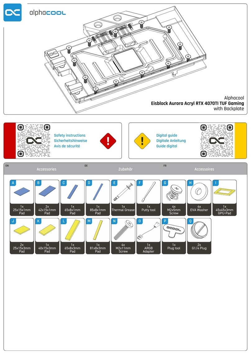
Alphacool
Alphacool Eisblock Aurora Acryl RTX 4070TI TUF Gaming manual
HighPoint
HighPoint RocketRAID 3700 Series user guide

Boca Systems
Boca Systems M73-APO01 user manual
Lattice Semiconductor
Lattice Semiconductor CertusPro-NX Usage Guide

RAK
RAK RAK19001 quick start guide

