manuals.online logo
Brands
  1. Home
  2. •
  3. Brands
  4. •
  5. RAK
  6. •
  7. Computer Hardware
  8. •
  9. RAK RAK19001 User manual

RAK RAK19001 User manual

Documentation Center
RAK19001 Quick Start Guide
This guide introduces the RAK19001 WisBlock Base Board and how to use it.
Prerequisite
What Do You Need?
Before going through each and every step on using the RAK19001 WisBlock Base Board, make sure to prepare
the necessary items listed below:
Hardware
RAK19001 WisBlock Dual IO Base Board
Your choice of WisBlock Core
Your choice of WisBlock Modules .
It is highly recommended to also check the dedicated quick start guide that you can follow on various WisBlock
Modules. Each quick start guide of these modules contains the detailed steps on how to open the example
codes and upload them to the WisBlock Core.
Li-Ion/LiPo battery (optional)
Solar charger (optional)
Type-C USB cable for programming and debugging
Software
Based on the choice of the WisBlock Core, select a Development Environment:
Programming via Arduino IDE
RAKwireless BSP support for Arduino
In Arduino IDE, once you installed the BSP, the examples for WisBlock Core will be automatically included on
the list of examples.
Programming via PlatformIO IDE:
RAKwireless WisBlock modules in PlatformIO
Product Configuration
Overview
To give you a better understanding of how the WisBlock Base works, the block diagram RAK19001 is provided in
this section.
Block Diagram
The block diagram shown in Figure 1 shows the internal architecture and external interfaces of the RAK19001
board.
Documentation Center
Figure 1: RAK19001 WisBlock Base block diagram
The MCU in the WisBlock Core module offers the I2C, UART, and SPI data buses to the sensor and IO modules.
Through these buses, the MCU can control and retrieve data from the sensors. The RAK19001 WisBlock Base
board connects all these modules.
The RAK19001 is designed to be powered by either rechargeable or non-rechargeable battery. The rechargeable
battery it supports is Li-Ion and provides the necessary charger IC on-board. The charger circuitry can be
connected to a wall outlet charger through the Type-C USB connector or via the solar panel connector.
A high-efficiency step-down converter with a low quiescent current is used for generating 3.3 V. This 3.3 V power
supply drives the consumption of the WisBlock Core module and the sensor modules.
3V3_S is another 3.3 V power supply, it can be controlled by the MCU to disconnect the power to the sensor and
interface modules during idle periods. 3V3_S is controlled by an IO2 pin on the WisBlock Core board.
Set IO2=1, 3V3_S is on.
Set IO2=0, 3V3_S is off.
Hardware Setup
RAK19001 WisBlock Base Board Installation Guide
RAK19001 WisBlock Base Board is the main board that allows you to attach MCU, sensors, and IO modules
through the standardized expansion connectors. These connectors provide a data bus interconnection between
the modules attached to the RAK19001 Base Board.
This guide shows the details related to the installation of modules into the RAK19001 Base board.
Attaching a WisConnector
The WisConnector is the interface between the RAK19001 module and the WisBlock Core, Sensor, and IO
modules. Before connecting these modules, read the following instructions:
📝
NOTE:
This guide uses two arrows. Refer to Figure 2 for its representation.
Documentation Center
Figure 2: Notation within the guide
1. Align the connectors. Keep the header parallel and place it lightly in the corresponding lap joint of the socket.
Figure 3: Alignment of WisConnector
2. Fit the connector. Tilt one end of the connector (header) less than 20 degrees, while do not apply force during
this process, gently place the other end in parallel.
Figure 4: Fit the WisConnector’s header inside of the socket
3. After the above alignment steps, the header and socket are matched but still not buckled.
Figure 5: WisConnector’s header matched inside of the socket
4. Apply forces evenly by pressing in parallel, then there will be a sound confirming the completion of the buckling.
Figure 6: Apply forces to buckle the heard to the socket
Documentation Center
5. In the process of buckling and applying force, avoid the application of uneven force on both sides.
Figure 7: Avoid applying uneven forces
6. When the buckling process is completed, check that the header and socket are kept in parallel.
Figure 8: Correct way to buckle the WisConnector’s header to the socket
7. If after buckling, the header and socket are not in a parallel state (not fully assembled in one place), then press
the even force on both sides of the long side to complete the correct buckling.
Figure 9: WisConnector’s header is not parallel to the socket
8. When the aforementioned steps are not completed yet, do not apply force to buckle. Otherwise, there will be a
risk to damage the connector. When the connector cannot be smoothly buckled down, repeat the alignment
step.
Detaching a WisConnector
1. To disconnect the header from the socket, pull out in parallel with even forces.
Figure 10: Correct way: Applying even forces to detach the header from the socket
2. Avoid pulling out the header asymmetrically in the long-side direction.
Documentation Center
Figure 11: Wrong way: Applying uneven forces to detach the header from the socket
3. The short-side of the connector can be pulled out asymmetrically, but apply the force vertically and avoid
rotating the header.
Figure 12: Wrong way: Do not rotate the header
4. Avoid applying forces in a single corner.
Figure 13: Wrong way: Do not apply force in a single corner of the header
Assembling a WisBlock Module
WisBlock Core
A WisBlock Core module is designed to be installed on the CPU slot of the RAK19001 Base Board. As shown in
Figure 14, the location is properly marked by silkscreen. Follow carefully the procedure defined in attaching a
WisConnector section in order to attach a Core module. Once attached, fix the module with one or more pieces of
M1.2 x 3 mm screws depending on the WisBlock Core.
Documentation Center
Figure 14: WisBlock Core silkscreen on the RAK19001 Base Board
WisBlock Sensor
A WisBlock Sensor module is designed to be installed on the sensor slot of the RAK19001 Base Board. There are
six (6) available sensor slots in the RAK19001 Base Board. As shown in Figure 15, the location of the slots is
properly marked by silkscreen. Follow carefully the procedure of the section, attaching a WisConnector, to attach a
WisBlock Sensor module. Once attached, fix the module with an M1.2 x 3 mm screw.
Figure 15: WisBlock Sensor silkscreen on the RAK19001 Base Board
WisBlock IO
A WisBlock IO module is designed to be installed on the IO slot of the RAK19001 Base Board. There are two (2)
IO slots in the RAK19001 Base Board. As shown in Figure 16, the location is properly marked by silkscreen.
Follow carefully the procedure of the section, attaching a WisConnector, to attach a WisBlock IO module. Once
attached, fix the module with three pieces of M1.2 x 3 mm screws.
Figure 16: WisBlock IO silkscreen on the RAK19001 Base Board
Documentation Center
Disassembling a WisBlock Module
1. The procedure to disassemble any type of WisBlock modules is the same. As shown in Figure 17, first, remove
the screws.
Figure 17: Removing screws from the WisBlock module
2. Once the screws are removed, on the PCB of a WisBlock module, there is a silkscreen that shows the correct
location where force can be applied. By applying even force under the marked area, the module can be
detached from the Base Board. See Figure 18 and Figure 19.
Figure 18: Detaching silkscreen on the WisBlock module
Figure 19: Applying even forces on the proper location of a WisBlock module to detach the module from the Base Board
Battery Selector
The RAK19001 supports both rechargeable and non-rechargeable batteries. You can also use this slide switch as
a power on/off switch to disconnect the battery from the board.
Documentation Center
Figure 20: Battery selector switch
Non-Rechargeable Battery
Various non-rechargeable batteries are supported by the RAK19001 as long as it is in the voltage range of 3.3 to
5.5 V. The onboard connector used on the non-rechargeable battery is FWF20009-S02S22W1B . The matching
connector housing is FHG20005-S02M2W1B , and the connector tin-plate pin is FT20004-F2H .
Figure 21: Non-Rechargeable battery connector pin
Rechargeable Battery
RAK19001 can be powered by a rechargeable Li-Ion/LiPo battery via the dedicated connectors, as shown in
Figure 22. The matching connector for the rechargeable battery wires is a JST PHR-2 2 mm pitch female . A
cable assembly for the rechargeable battery connector is also available for purchase in RAK store .
Figure 22: Rechargeable battery connector pin
Documentation Center
⚠
WARNING
Battery can cause harm if not handled properly.
Only 3.7-4.2 V Rechargeable LiPo batteries are supported. It is highly recommended not to use other
types of batteries with the system unless you know what you are doing.
Make sure the battery wires, both rechargeable and non-rechargeable, match the polarity on the
RAK19001 board. Not all batteries have the same wiring.
Solar Panel Connection
The battery can be recharged, as well, via a small Solar Panel, as shown in Figure 23. The matching connector
for the solar panel wires is an JST ZHR-2 1.5 mm pitch female . A cable assembly for the solar panel connector
is also available for purchase in RAK store .
Figure 23: Solar panel connector V+ and GND
⚠
WARNING
Only 5 V solar panels are supported. Do not use 12 V solar panels. It will destroy the charging unit and
eventually other electronic parts.
The GND pin of the Solar Panel Connector is located on edge of the board. Make sure the solar panel
wires match the polarity on the RAK19001 board.
Software Setup
The WisBlock Core is designed to be interfaced with other WisBlock Modules like sensors, displays, and other
interfaces. To make useful devices, you need to upload a source code to the WisBlock Core. Before you continue,
you should have already set up either an Arduino BSP or PlatformIO .
WisBlock Examples Repository
To quickly build your IoT device with less hassle, example codes for WisBlock Core are provided. You can access
the codes on the WisBlock Example code repository . The example codes on folder common are compatible
with RAK4631, RAK11200, and RAK11310 WisBlock cores.
Last Updated: 7/29/2022, 10:17:19 PM
Documentation Center
RAK19001 WisBlock Dual IO Base Board
Datasheet
WisBlock Dual IO Base Board Overview
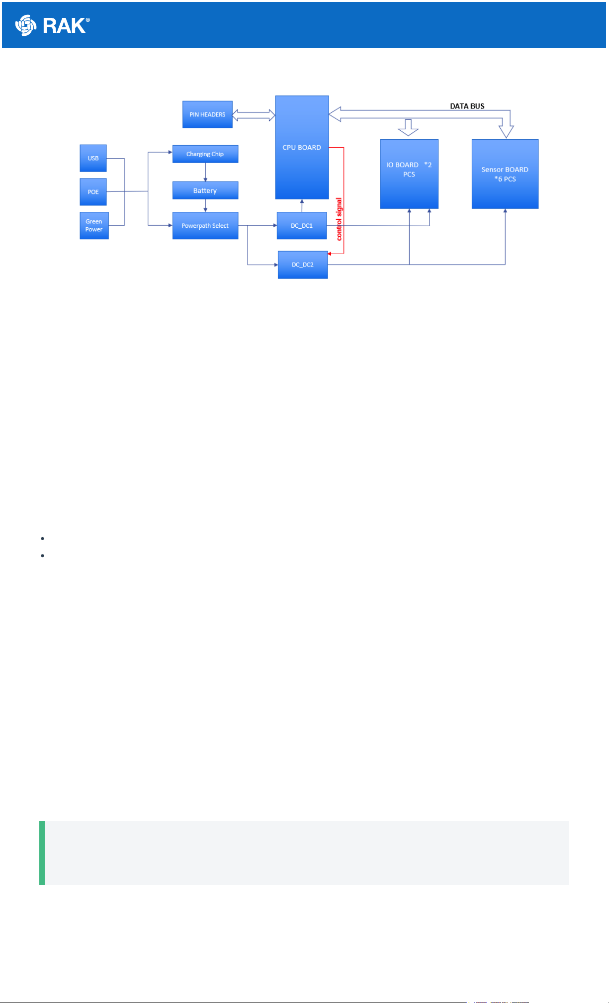
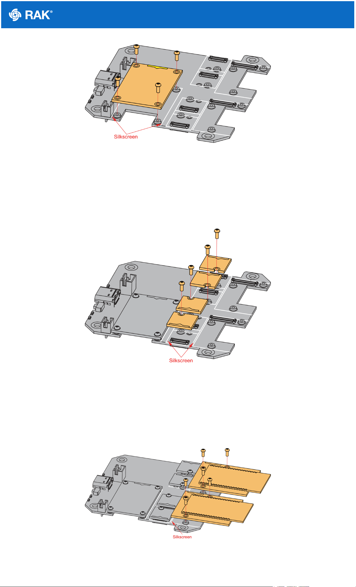
RAK19001 is a WisBlock Base board that connects WisBlock Core and WisBlock Modules. It provides the
power supply and interconnection to the modules attached to it. It has one slot reserved for the WisBlock Core
module, two IO slots, and six sensor slots A to F for WisBlock Modules. Also, there are two 2.54 mm pitch
headers that expose all key input-output pins of the WisBlock Core that includes UART, I2C, SPI, and many IO
Pins.
For convenience, there is a Type-C USB connector that is connected directly to WisBlock Core MCU’s USB port (if
supported) or to a USB-UART converter depending on the WisBlock Core. The USB-C connection can be used for
uploading firmware, serial communication, and charging A rechargeable battery. RAK19001 also includes a slide
switch to select between rechargeable and non-rechargeable batteries.
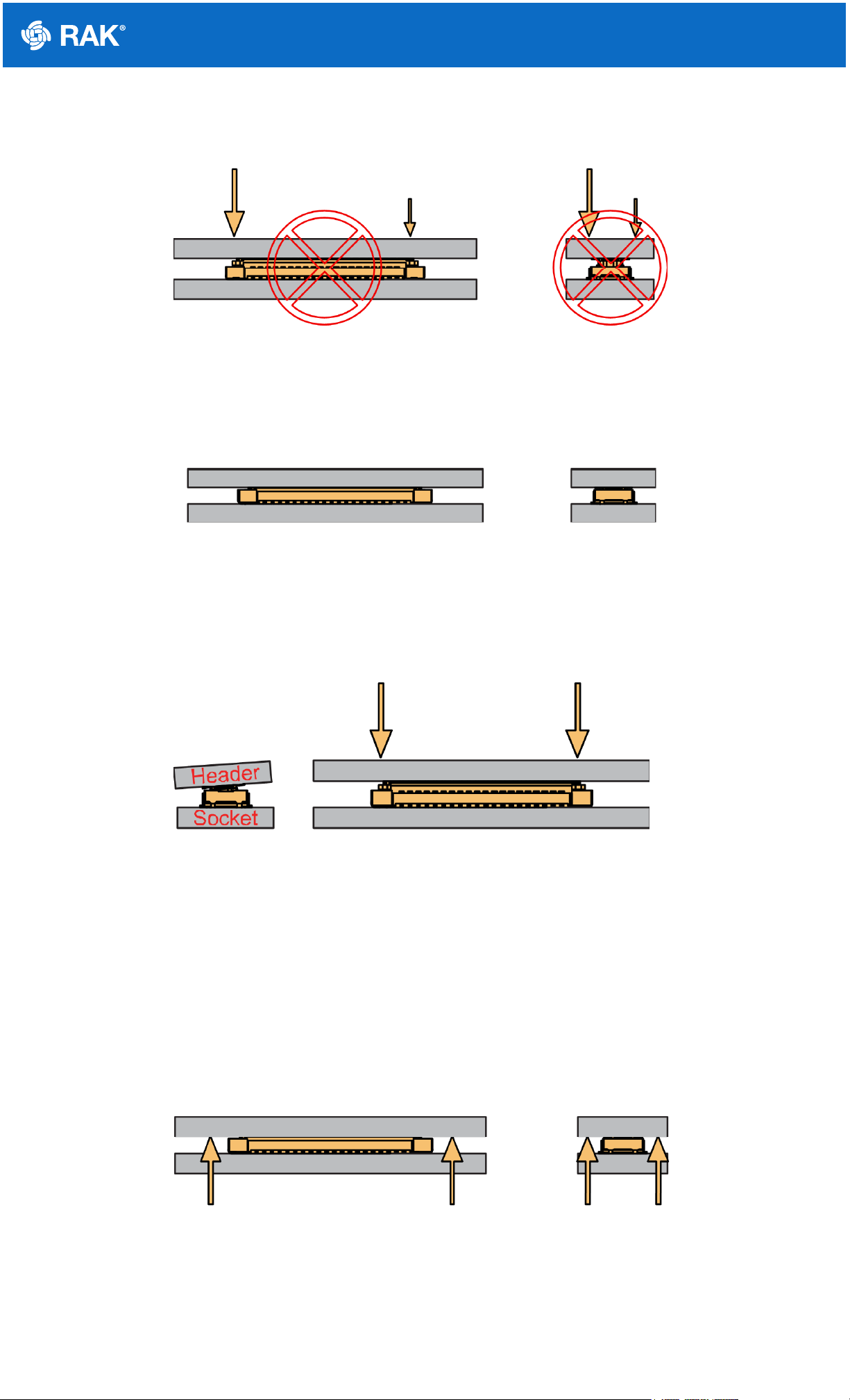
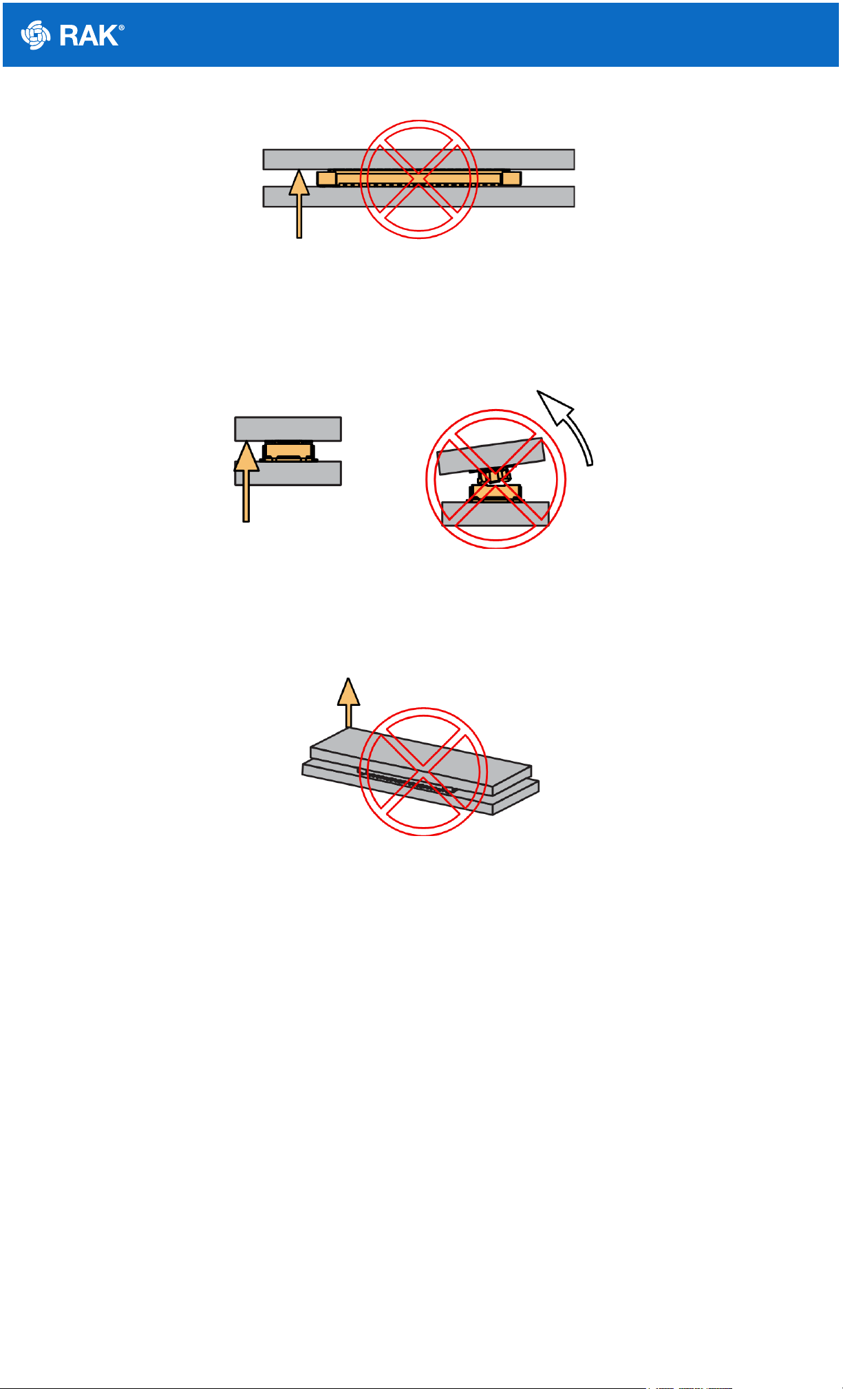
WisBlock Modules are connected to the RAK19001 WisBlock Base board via high-speed board-to-board
connectors. They provide secure and reliable interconnection to ensure the signal integrity of each data bus. A
set of screws are used for fixing the modules, which makes it reliable even in an environment with lots of
vibrations.
Additionally, it has two user-definable LEDs, one power supply/charging indicator LED, and one user-defined
button.
If you can't find a module that fits your IoT requirements, use the standard connectors of WisBlock to develop your
own specific function module. WisBlock supports open-source hardware architecture and you can find tutorials
showing how to create your own Awesome WisBlock module.
Main Features
Flexible building block design, which enables modular functionality and expansion
High-speed interconnection connectors in the WisBlock Base board to ensure signal integrity
Multiple headers and modules slots for WisBlock modules
Two (2) IO slots
Six (6) sensor (A to F) slots
All key input-output pins of WisBlock Core are exposed via headers
Access to various communication bus via headers: I2C, SPI, UART, and USB
One user-defined push button switch
Power supply
Supports both 5 V USB, 3.7 V rechargeable battery, and 3.3 to 5.5 V non-rechargeable battery as power
supply
The power supply for the WisBlock modules boards can be controlled by the WisBlock Core modules to
minimize power consumption
Slide switch to select between a rechargeable or non-rechargeable battery
Size
60 x 67 mm
Specifications
Overview
Documentation Center
Board Overview
Figure 1: RAK19001 WisBlock Base top (left) and bottom (right) view
Block Diagram
The block diagram in Figure 2 shows the internal architecture and external interfaces of the RAK19001 board.
Figure 2: RAK19001 WisBlock Base block diagram
Hardware
The hardware specification is categorized into six parts. It discusses the interfacing, pinouts, and their
corresponding functions and diagrams. It also covers the electrical, mechanical, and environmental parameters
that include the tabular data of the functionalities and standard values of the RAK19001 WisBlock Dual IO Base
Board.
Interfaces
RAK19001 WisBlock Base board provides the following interfaces, headers, a button, and WisConnectors:
1 WisBlock Core module
2 IO slots for WisBlock modules
6 Sensor slots A-F for WisBlock modules
1 Type-C USB port for programming and debugging
3.7 V rechargeable battery connector
Non-rechargeable battery connector
5 V Solar panel connector
2 Headers for complete access to BOOT, I2C, SPI, UART, USB, and IO pins
2 User-defined LEDs
1 Power supply/charging indicator LED
Documentation Center
1 User-defined button
1 Reset button
Figure 3: RAK19001 part labels
Type-C USB Port
The Type-C USB connector is compliant with the USB 2.0 specification. This USB interface directly communicates
with the connected WisBlock Core module. It is also used as a charging input port for the battery. Here are some
of the advantages of the Type-C USB connector:
Smaller and reversible connector shape
Port can be input or output
Fast battery charging
Figure 4: USB Type-C receptacle pinout
J10 and J15 Headers (Core IO Pins)
On the WisBlock Dual IO Base board, there are a total of 40 2.54 mm pitch headers for IO access and extension.
These IO pins are distributed to J10 and J15 pin headers with the corresponding label at the back of the board.
The arrangement of the pins is based on the 40-pin WisConnector of the WisBlock Core.
📝
NOTE
BOOT pin is used on startup configuration or sequence of the WisBlock Core connected to it. It is
commonly used for uploading the bootloader and/or application firmware. The requirements of the state of
the BOOT pin depend on the specific model of the WisBlock Core used.
Documentation Center
Figure 5: J10 and J15 pin header label in bottom side
J11 and J12 Headers (I2C and UART)
A dedicated header is available as well to have access to commonly used serial interfaces I2C and UART.
Figure 6: J11 and J12 (I2C and UART) pin header label in bottom side
Battery Connectors
Figure 7 and Figure 8 show the battery connectors V+(positive) and GND on both rechargeable and non-
rechargeable batteries.
The matching connector for the rechargeable battery wires is a JST PHR-2 2 mm pitch female . A cable
assembly for the rechargeable battery connector is also available for purchase in RAK store .
Figure 7: Rechargeable battery connector pin label V+ and GND
The onboard connector used on the non-rechargeable battery is FWF20009-S02S22W1B . The matching
connector housing is FHG20005-S02M2W1B , and the connector tin-plate pin is FT20004-F2H .
Documentation Center
Figure 8: Non-Rechargeable battery connector pin label V+ and GND
Figure 9 shows how to select the battery type used for the project. The battery selector is based on the SS-12D10
slide SPDT switch . You can also use this slide switch as a power on/off switch to disconnect the battery from
the board.
Figure 9: Battery selector switch
⚠
WARNING
The voltage of the rechargeable battery must not exceed 4.3 V.
The voltage of the non-rechargeable battery must not exceed 5.5 V.
Solar Panel Connector
Figure 10 shows the solar panel connector V+(Vin) and GND. The matching connector for the solar panel wires is
an JST ZHR-2 1.5 mm pitch female . A cable assembly for the solar panel connector is also available for
purchase in RAK store .
Figure 10: Solar panel connector V+ and GND
⚠
WARNING
The output voltage of the solar panel must not exceed 5.5 V. Otherwise, it may cause permanent damage
to the board.
Documentation Center
LEDs
Three LEDs are used to indicate the operating status. Below are the functions of the LEDs:
🔴
Red LED - Connected to the charger chip to indicate the charger status. When the battery is charging, this
red LED is on. When the battery is full, this LED is weak light or off.
 Green LED - Connected to the MCU module, controlled by MCU defined by the user.
🔵
Blue LED - Connected to the MCU module, controlled by MCU defined by the user.
RESET Push Button
The Reset Push Button shown in Figure 3 of interfaces section is connected to the MCU module. When pushed, it
resets the MCU.
User Programmable Push Button
The User Programmed Push Button shown in Figure 3 of interfaces section is connected to the SW1 pin of the
WisBlock Core.
Pin Definition
Connector for WisBlock Core
The WisCore module connector is a 40-pin board-to-board connector. It is a high-speed and high-density
connector, with an easy attaching mechanism.
Figure 11: WisBlock Core module 40-pin connector
The table below shows the pinout of the 40-pin MCU module connector:
Documentation Center
As for the following table, it shows the definition of each pin of the WisBlock Core connector:
Pin
Number
Function Name of WisBlock
Base
Pin
Number
Function Name of WisBlock
Base
1 VBAT 2 VBAT
3 GND 4 GND
5 3V3 6 3V3
7 USB+ 8 USB–
9 VBUS 10 SW1
11 TXD0 12 RXD0
13 RESET 14 LED1
15 LED2 16 LED3
17 VDD 18 VDD
19 I2C1_SDA 20 I2C1_SCL
21 ADC_VBAT 22 AIN1
23 BOOT0 24 IO7
25 SPI_CS 26 SPI_CLK
27 SPI_MISO 28 SPI_MOSI
29 IO1 30 IO2
31 IO3 32 IO4
33 TXD1 34 RXD1
35 I2C2_SDA 36 I2C2_SCL
37 IO5 38 IO6
39 GND 40 GND
Documentation Center
Pin
Number Pin Name Type Description
1 VBAT S Power supply from battery
2 VBAT S Power supply from battery
3 GND S Ground
4 GND S Ground
5 3V3 S 3.3 V power supply
6 3V3 S 3.3 V power supply
7 USB+ I/O USB D+
8 USB– I/O USB D–
9 VBUS S USB VBUS
10 SW1 I/O Not connected
11 TXD0 I/O MCU UART0 TX signal
12 RXD0 I/O MCU UART0 RX signal
13 RESET I Connected to the reset switch, for MCU reset
14 LED1 I/O LED for battery charging indication
15 LED2 I/O LED for custom usage
16 LED3 I/O LED for custom usage
17 VDD S Generated by MCU module for power sensor board if the MCU IO
level is not 3.3 V
18 VDD S Generated by MCU module for power sensor board if the MCU IO
level is not 3.3 V
19 I2C1_SDA I/O The first set of I2C data signal
20 I2C1_SCL I/O The first set of I2C clock signal
21 ADC_VBAT A Analog input for ADC (Connected to a battery)
22 AIN1 A Analog input for ADC
23 BOOT0 I For ST MCU only. The MCU will enter boot mode if this pin is
connected to VDD.
Documentation Center
Connectors for WisBlock Sensor
The WisBlock sensor module connector is a 24-pin board-to-board connector.
⚠
WARNING
The WisBlock 24-pin connectors have the same connections for 3V3_S, GND, I2C, and SPI. However,
UART and IO pins are not the same for all slots.
Pin
Number Pin Name Type Description
24 IO7 I/O Not connected
25 SPI_CS I/O SPI chip select signal
26 SPI_CLK I/O SPI clock signal
27 SPI_MISO I/O SPI MISO signal
28 SPI_MOSI I/O SPI MOSI signal
29 IO1 I/O General purpose IO
30 IO2 I/O Used for 3V3_S enable
31 IO3 I/O General purpose IO
32 IO4 I/O General purpose IO
33 TXD1 I/O MCU UART1 RX signal
34 RXD1 I/O MCU UART1 RX signal
35 I2C2_SDA I/O The second set of I2C data signal
36 I2C2_SCL I/O The second set of I2C clock signal
37 IO5 I/O General purpose IO
38 IO6 I/O General purpose IO
39 GND S Ground
40 GND S Ground
Documentation Center
Figure 12: WisBlock 24-pin module connector
Pinout definition for standard size slot (A-D):
Pinout definition for double size sensor slot (E and F):
DCBAPin
Number
Pin
Number A B
NC NC NC TXD0 1 2 GND GND
SPI_CS SPI_CS SPI_CS SPI_CS 3 4 SPI_CLK SPI_
SPI_MISO SPI_MISO SPI_MISO SPI_MISO 5 6 SPI_MOSI SPI_
I2C1_SCL I2C1_SCL I2C1_SCL I2C1_SCL 7 8 I2C1_SDA I2C1
VDD VDD VDD VDD 9 10 IO2 IO1
3V3_S 3V3_S 3V3_S 3V3_S 11 12 IO1 IO2
NC NC NC NC 13 14 3V3_S 3V3_
NC NC NC NC 15 16 VDD VDD
NC NC NC NC 17 18 NC NC
NC NC NC NC 19 20 NC NC
NC NC NC NC 21 22 NC NC
GND GND GND GND 23 24 RXD0 NC
Documentation Center
As for the following table, it shows the pin name and description of each pin in the 24-pin WisBlock module
connector.
Connector F Connector E Pin Number Pin Number Connector E Connector F
TXD1 TXD0 1 2 GND GND
SPI_CS SPI_CS 3 4 SPI_CLK SPI_CLK
SPI_MISO SPI_MISO 5 6 SPI_MOSI SPI_MOSI
I2C1_SCL I2C1_SCL 7 8 I2C1_SDA I2C1_SDA
VDD VDD 9 10 IO3 IO5
3V3_S 3V3_S 11 12 IO4 IO6
NC NC 13 14 3V3_S 3V3_S
NC NC 15 16 VDD VDD
NC NC 17 18 NC NC
NC NC 19 20 NC NC
NC NC 21 22 NC NC
GND GND 23 24 RXD0 RXD1

Other RAK Computer Hardware manuals

RAK RAK1920 User manual

RAK

RAK RAK1920 User manual

RAK RAK7204 User manual

RAK

RAK RAK7204 User manual

RAK RAK3372 User manual

RAK

RAK RAK3372 User manual

RAK RAK1901 User manual

RAK

RAK RAK1901 User manual

RAK RAK5005-O User manual

RAK

RAK RAK5005-O User manual

RAK LB801 User manual

RAK

RAK LB801 User manual

RAK RAK13009 User manual

RAK

RAK RAK13009 User manual

Popular Computer Hardware manuals by other brands

Renesas RYZ012x1 quick start guide

Renesas

Renesas RYZ012x1 quick start guide

Commell FS-A78 user manual

Commell

Commell FS-A78 user manual

alphatronics PSTN-2-IP GPRS installation manual

alphatronics

alphatronics PSTN-2-IP GPRS installation manual

Meinberg DI32 Characteristics

Meinberg

Meinberg DI32 Characteristics

Ratoc Systems CB32U user guide

Ratoc Systems

Ratoc Systems CB32U user guide

ADDER DDC Ghost user guide

ADDER

ADDER DDC Ghost user guide

ViewCast OSPREY 240E user guide

ViewCast

ViewCast OSPREY 240E user guide

Balluff BIS C-6002 manual

Balluff

Balluff BIS C-6002 manual

TC-Helicon Quintet user manual

TC-Helicon

TC-Helicon Quintet user manual

ESD ECS-CPCIs/FPGA Hardware manual

ESD

ESD ECS-CPCIs/FPGA Hardware manual

iSystem Target Board LPC2138 user guide

iSystem

iSystem Target Board LPC2138 user guide

Intel RH80536GC0332M - Pentium M 1.8 GHz Processor datasheet

Intel

Intel RH80536GC0332M - Pentium M 1.8 GHz Processor datasheet

StarTech.com PEX4S553B instruction manual

StarTech.com

StarTech.com PEX4S553B instruction manual

Campbell CR23X overview

Campbell

Campbell CR23X overview

Artaflex AWAC24UR user manual

Artaflex

Artaflex AWAC24UR user manual

IBM 7133 D40 Service guide

IBM

IBM 7133 D40 Service guide

AEV S.p.A. XTREME II operating manual

AEV S.p.A.

AEV S.p.A. XTREME II operating manual

Cypress Semiconductor CY7C1416AV18 Specification sheet

Cypress Semiconductor

Cypress Semiconductor CY7C1416AV18 Specification sheet

manuals.online logo
manuals.online logoBrands
  • About & Mission
  • Contact us
  • Privacy Policy
  • Terms and Conditions

Copyright 2025 Manuals.Online. All Rights Reserved.