manuals.online logo
Brands
  1. Home
  2. •
  3. Brands
  4. •
  5. InPOWER
  6. •
  7. Controllers
  8. •
  9. InPOWER DBT-MDF20 User manual

InPOWER DBT-MDF20 User manual

Medium Duty Ford Throttle Control
DBT-MDF20
InPower’s Medium Duty application Data Bus Throttle
(DBT-MDF20) does more than just provide high idle and
PTO when and how you need it. It can also output any
engine signal you need.
Each module has three adjustable RPM settings and two
remote RPM controls, as well as six chassis outputs for
any signal, such as Park, Reverse or Engine Run. The
DBT-MDF20 is provides breakout of PTO Signals for the
user, and utilizes Ford SEIC functions and communicates
across CAN. It can be wired to monitor auxiliary battery
voltage, to a 0 to 5V sensor, or a 2nd (remote) accelerator
pedal.
The module ships with two cables, one of which
connects to the SDLC port, an optional sensor and
power, and the other of which connects to all inputs
and outputs, including PTO. Diagnostic LEDs aid in
troubleshooting, while the lightweight, low prole design
makes installation easy.
• SEIC signals - T1, +12V VAux, ADJ, T2, and 5V
• Output Park (+12Vdc); On F750s: Neutral (+12Vdc)
• Output Park Brake (GND)
• Output Sevice Brake Output (+12V)
• Output Reverse (+12Vdc)
• Output Engine Run (+12Vdc)
• Three Adjustable RPMs
• Two Remote RPM controls
• Utilizes FORD SEIC Functions
• Six Engine Signal Outputs
• CAN communication
• Diagnostic LEDs
• Affordable and Reliable
Model Number Vehicle Notes
DBT-MDF20 Ford
DBT-MDF20-C Ford Contact Inpower for Programmed Options
Examples: Start/Stop, Auxillary Battery
Monitor, Custom Chassis Signals
Note: Custom Modules available, if you need custom outputs or signals from the databus not
availableinourstandardconguration.
Technical Description
Available I/O Signals
Features
Ordering Guide
Product Data Sheet
PDS-219
For Additional Integration Information Please refer to the DBT-MDF20 OM-323 Owners Manual
See: http://www.inpowerelectronics.com/throttle_selector
Product Data Sheet
PDS-219
Mechanical Drawing
© Copyright 2020 InPower LLC
PDS-219 20200120 www.InPowerLLC.com
Specications subject to change without notice.
Medium-Duty Vehicle Throttle
DBT-MDF20
DBT-MD I/O Harness
Secure Data OBDII
Connector
Ford
SDLC
Gateway
On
Truck
DBT-MDF20 SDLC
Throttle Harness
P1
P2
J1
J2
www.InPowerLLC.com
Made in the USA
LOT:1234567890
Diagnostic
LEDs
- Bus
- RPM1
- RPM2
- RMT 0-5V
- RMT PWM
- RPM STBY
- PARK
- PARKBRAKE
- S BRAKE
- V SPEED
- ACCELERATOR
DATA BUS THROTTLE
MODEL DBT-MDF20
Gateway to Chassis
Group 1
Group 2
Group 3
DBT-MD I/O Harness
SDLC
Gateway
Connector
Original SDLC
Gateway Plug
SDLC Y
Harness Plug SDLC Y Harness
Connector
RPM Adj
Remote RPM
etc
P1
P2
J2
J1
DBT-MDF20 SDLC Throttle Harness Sensors and Power
P3 Color Signal
Pin2 Black GND for Remote Accel Pedal
Pin3 Orange T1
Pin7 Red +12V
Pin8 Violet VAux
Pin9 Gray ADJ
Pin10 Pink T2
Pin11 White 5V
1
2
3
4
5
6
7
8
9
10
11
12
1
2
3
4
5
6
7
8
9
10
11
12
13
14
15
16
P1 Color Signal
Pin2 White PTO-Relay
Pin8 Brown PTO-Vref
Pin13 Orange PTO-Req2
Pin14 Violet PTO-Req1
Pin16 Gray PTO RPM
GROUP 1 - SEIC
P1 Color Signal
Pin3 Brown In Low 2
Pin4 Pink In High 1
Pin5 Tan In High 2
Pin6 Violet In High 3
Pin7 Dk Blue In High 4
GROUP 2 - Inputs
P1 Color Signal
Pin1 Dk Green Out Low 2
Pin9 Pink Out High 6
Pin10 Tan Out High 4
Pin11 Violet Out High 5
Pin12 Dk Blue Out High 3
Pin15 Gray Out Low 1
GROUP 3 - Outputs
GROUP 1 - SEIC
GROUP 2 - Inputs
GROUP 3 - Outputs
J1
J2
www.InPowerLLC.com
Made in the USA
LOT: 1234567890
Diagnostic
LEDs
- Bus
- RPM1
- RPM2
- RMT 0-5V
- RMT PWM
- RPM STBY
- PARK
- PARK BRAKE
- S BRAKE
- V SPEED
- ACCELERATOR
DATA BUS THROTTLE
MODEL DBT-MDF20
3.74”
4.4”
2.62”
0.2” dia
0.8”
0.4”
Chassis Ready Conditions:
 1.Enginerunningatidlespeedbelow1,000RPM.
 2.Novehiclespeed.
 3.AutomatictransmissioninPark.
 4.Servicebrakenotdepressed.
 5.Acceleratorpedalnotdepressed.
 6.Parkingbrakeset.
 7.NoDiagnosticTroubleCode(DTC).
 CheckEnginelightmustbeoff.
LED Status Indicators:
BUS Solid indicates bus communication
RPM1  IndicateselevatedxedspeedmodeRPM1
RPM2  IndicateselevatedxedspeedmodeRPM2
RMT 0-5V Operating in Remote Adjust (remote accel)
RMT PWM Not Used
RPM STBY Stdby RPM setting
PARK Service Brake Engaged
PARK BRAKE Park Brake Engaged
S BRAKE Service Brake Engaged
V SPEED Vehicle Speed
ACCELERATOR Accelerator Engaged
Power Requirements & Notes
+12 volts: Sourced from SEIC connector
Ground: Connects to Solid Battery Ground
RPM1: 1500 Factory Preset
RPM2: 1200 Factory Preset
Speed Adjust Input: Adjusts preset RPM to desired value
between 900 and 3000 RPM - (SEIC Max),
   (ChassisandEngineDependent).
Adjusting Preset RPM: Select RPM1, RPM2, etc to be adjusted with
12VDC, apply +12 to Grey Adjust Wire to
increase, apply GND to decrease
(50RPM per second) 25 rpm per bump (less
than a second)
Dimensions:  4.4Lx2.62Wx0.8Hinches

Other manuals for DBT-MDF20

1

Other InPOWER Controllers manuals

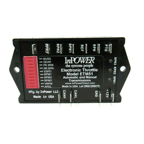
InPOWER ETM67A User manual

InPOWER

InPOWER ETM67A User manual

InPOWER ETM51 User manual

InPOWER

InPOWER ETM51 User manual

InPOWER SBF94 User manual

InPOWER

InPOWER SBF94 User manual

InPOWER SBF90 User manual

InPOWER

InPOWER SBF90 User manual

Popular Controllers manuals by other brands
Kelly KLS6045H user manual

Kelly

Kelly KLS6045H user manual

Dimplex RXPW4 quick start guide

Dimplex

Dimplex RXPW4 quick start guide

Deltran Battery Tender Solar Charger Controller instruction manual

Deltran

Deltran Battery Tender Solar Charger Controller instruction manual

Agrowtek MX1i instruction manual

Agrowtek

Agrowtek MX1i instruction manual

Vacon NX user manual

Vacon

Vacon NX user manual

Siemens SITOP UPS1600 under STEP 7 V12 Getting started

Siemens

Siemens SITOP UPS1600 under STEP 7 V12 Getting started

Linak TECHLINE LA33 user manual

Linak

Linak TECHLINE LA33 user manual

Broan VBATHW Installation and user guide

Broan

Broan VBATHW Installation and user guide

BRT Systems PANL user guide

BRT Systems

BRT Systems PANL user guide

Interpump Group HM operating instructions

Interpump Group

Interpump Group HM operating instructions

Nevco 134 Operator instructions

Nevco

Nevco 134 Operator instructions

Volt Polska AVR PRO 1000 product manual

Volt Polska

Volt Polska AVR PRO 1000 product manual

Siemens LOGO! 0BA7 manual

Siemens

Siemens LOGO! 0BA7 manual

valent RyzUp SmartGrass PGR quick start guide

valent

valent RyzUp SmartGrass PGR quick start guide

SMC Networks IZN10 Series Operation manual

SMC Networks

SMC Networks IZN10 Series Operation manual

Aaeon TKS-G20-LN05 manual

Aaeon

Aaeon TKS-G20-LN05 manual

ARAG 4669 Series General instruction for installation use and maintenance

ARAG

ARAG 4669 Series General instruction for installation use and maintenance

Omnitronic DXO-24E Driver installation

Omnitronic

Omnitronic DXO-24E Driver installation

manuals.online logo
manuals.online logoBrands
  • About & Mission
  • Contact us
  • Privacy Policy
  • Terms and Conditions

Copyright 2025 Manuals.Online. All Rights Reserved.