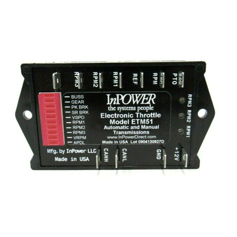
InPOWER ETM67A User manual

OWNERS MANUAL
Model ETM67A & ETM68A
Electronic Throttle Module for
2006+ hevy/GM Gas and Diesel
Engines with Automatic Transmissions
A. Introduction
This owners manual describes the InPower Model ETM67A and ETM68A
electronic throttles used on hevy & GM vehicles with gas and diesel
engines. Note that the ETM67A and ETM68A systems support the exact
same vehicles, but differ only in functionality. The ETM68A provides
three fast idle preset speed modes (RPM1, RPM2 & RPM3). The
ETM67A provides three fast idle preset speed modes (RPM1, RPM2 &
RPM3) plus a harge Protect ( HRG) mode.
The electronic throttle installation requires customer-supplied control
wiring to select the required mode of operation. For example, a remote
toggle switch or a relay contact from a compressor or aerial lift circuit
could be wired to the RPM1 terminal on the electronic throttle controller
to activate the RPM1 fast idle mode. The RPM1 mode is then adjusted to
the desired fast idle engine speed rpm. Likewise, the RPM2 and RPM3
mode inputs could be wired if you need additional fast idle engine speed
functions.
The customer wiring connects to the electronic throttle module via 0.25
inch Faston terminals. The electronic throttle system is supplied with a
three foot data cable. This cable contains a 16-pin connector at one end
and 0.25 inch Faston terminals at the other end. The Faston terminals
will connect at the electronic throttle module and the 16-pin connector
plug will attach to the vehicle’s OBDII (On Board Diagnostic) data link
connector (DL ). The DL is usually located at the lower part of the
dash on the driver’s side.
8
InPOWER LL
3555 Africa Road
Galena, Ohio 43021 U.S.A
(740)548-0965
Www.InPowerDirect.com
© 2012 InPower LL
Owners Manual
Document: OM-64
Date: Oct. 3, 2007
Revision: G
Date: January 27, 2012
G. Mechanical Drawing
P
K
B
R
K
PK BRK
SR BRK
VSPEED
BUS
GEAR
RPM
1
RPM2
RPM3
HRG
APDL
R
P
M
3
A
N
H
3.50
4.00
R
P
M
2
A
N
L
R
P
M
1
G
N
D
+
1
2
V
P
T
O
R
P
M
1
R
P
M
2
R
P
M
3
0.50
0.1875
1.025
2.05
Preset speed calibration potentiometers (3 places)
System Data Link onnector (DL ) able
onnection to ETM Module (Faston terminals)
0.25 Inch Faston Terminals
All dimensions in inches. Not to scale.
3
ft. OBDII
Data Link
onnector
ontrol Module
OM-64G ETM67A & ETM068A

27
F. Wiring Diagram
GM HASSIS
0) Fully Released
1) Brake Applied
Ground
ustomer
Wiring
Parking Brake
Position Switch
hassis Ground
(Battery Neg.)
Fast Idle Switch
+12 V Ignition
(Fused)
OBD-II
Diagnostic
onnector
0
1
Off
Ground
On
RPM 3
RPM 2
+12 Volts
RPM 1
Optional Park Brake
Wiring:
Ground satisfies
the parking brake set
interlock.
Green - Pin 14
Yellow - Pin 6
DL able
(Supplied with
ETM67A/68A)
Shield - Pin 5
G
N
D
+
1
2
V
A
N
L
P
K
B
R
K
R
P
M
2
R
P
M
1
R
P
M
1
R
P
M
2
R
P
M
3
A
N
H
R
P
M
3
P
T
O
InPower
ETM67A/68A
Yellow
ANH
(Yellow)
View looking into connector:
8
16
7
15
6
14
5
13
12
43
1
1
10
21
9
PTO output is +12 volts at 3 amps and is set
when the throttle control is actively controlling
the engine rpm and the hassis Ready
onditions are satisfied. Do not connect any
+12 volt sources to this output terminal or
damage may result voiding the warranty.
Green
Shield
ANL
(Green)
H
R
G
harge Protect (Only on ETM67)
B. Vehicle Applications
The ETM67A and ETM68A support the following GM vehicle
configurations.
Model Year hassis Engine Transmission
2006, 2007, Silverado/Sierra lassic 6.6 L Diesel Automatic
2007i, 2008, 2500, 3500
2009, 2010
2007i, 2008, Silverado/Sierra lassic 6.0 L Gas Automatic
2009 2500, 3500
2006, 2007, Kodiac/Topkick 4500, 6.6 L Diesel Automatic
2007i, 2008, 5500
2009
2006 - 2010 Express, Savanna 6.6 L Diesel, Automatic
4.8 L & 6.0 L Gas
2007 - 2010 Tahoe/Suburban/Yukon 4.8 L , 5.3 L, 6.0 L, Automatic
& 6.2 L Gas
. Operation
When the vehicle is parked and hassis Ready onditions are satisfied,
the engine speed may be controlled by one of the three available preset
speed modes. The preset speed is adjusted by three calibration
potentiometers on the top of the ETM module.
hassis Ready onditions:
1. Parking brake is set.
2. Gear shift in “Park”
3. Foot is off the service brake
4. Foot is off the accelerator pedal
5. Vehicle is stationary (no speed)
6. Engine is started and idling below 1000 RPM
Modes Of Operation:
1. Three Preset RPM High Idle Modes:
Function: Increase idle to a preset rpm value
Terminals: RPM1, RPM2, RPM3
Activation: Apply +12 V to terminal
Range of alibration: 650 to 1460 rpm (Diesel), 650-2000 rpm
(Gas)
Type of Adjustment: Internal potentiometers
OM-64G ETM67A & ETM068A

36
2. Mode Priorities:
A mode priority selection scheme is provided that will eliminate conflicts if
more than one mode is selected at a time. In the case of one or more
modes being selected, the following priorities will be established:
RPM1 Highest - Will override all other modes
RPM2 Second - Will override lower modes
RPM3 Third - Will override lower mode
HRG Fourth
3. harge Protect Mode (Only on ETM67A):
Function: Varies rpm to maintain battery charge
voltage
ontrol Terminal: HRG
Activation: Apply +12V to HRG terminal
RPM Range: 900 to 1700 rpm
Battery Voltage Levels: 13.3 Vdc Increase rpm; 13.5 Vdc
Decrease rpm
Status Indicators
A 10 segment LED provides status and problem detection information.
Refer to the following table for coding of these functions. NOTE - These
LED indicators will only be powered when a Mode (RPM1, RPM2,
RPM3, HRG) is selected.
LED Status Indication
BUSS On Solid Module ON and functioning
BUSS Flashing Module ON, but a problem was
Detected with Data Buss
GEAR On Solid Transmission in PARK position
GEAR Flashing Transmission not in PARK position
PK BRK On Solid Park Brake set
PK BRK Flashing Park Brake not set
SR BRK On Solid Service Brake off
SR BRK Flashing Service Brake applied
VSPEED On Solid Vehicle is stationary
VSPEED Flashing Vehicle is moving
ontinued...
5. PTO Enable Wiring - Diesel Engines Only ( ontinued)
On 2009-2010 Gvans there is no PTO Enable function so the following
procedure must be used when going to high idle:
Step 1 Turn on the ruise ontrol
Step 2 Turn on the ETM67A/68A
Step 3 Press the ruise ontrol Set button
6. Wire the Mode Selection ontrols
The following wiring is required by the customer to select the operating
modes required to run the ETM system. You will need to supply contact
closures such as a toggle switch or relay contact to supply +12 volts at the
ETM module’s terminals for the required preset rpm modes (RPM1,
RPM2, RPM3 or HRG). It is important that the +12 volts used to feed the
mode select terminals is from the Ignition Switch power source, and it
should be properly fused. That is, it must be +12 volts when the Ignition
Switch is On, and zero volts when the Ignition Switch is Off.
7. Wire the Power and Ground
Install a wire from a good ground (battery negative) to the GND terminal
on the ETM67A/68A module. Install a Fast Idle Switch (not supplied with
ETM system) and wire one side of the switch to a source of +12 volts that
is fused and only powered when the ignition switch is in the On position.
Wire the other side of the switch to the +12V terminal on the ETM module
and to the contacts that select the RPM1, RPM2 & RPM3 modes (see
diagram on page 4).
E. Setup and alibration
The only calibration required is the speed rpm setting for the three preset
rpm modes (RPM1, RPM2 & RPM3). To perform the calibration activate
the desired preset mode, then adjust the respective speed calibration
potentiometer (RPM1, RPM2 or RPM3) for the required speed. NOTE -
The calibration potentiometers are located on the top of the module in
recessed holes. Take care to use a proper size screwdriver (3/64” /
1.5mm) or damage to the potentiometers may result, voiding the warranty.
D. Installation ( ontinued) . Operation ( ontinued)
OM-64G ETM67A & ETM068A

5
4
LED Status Indication
RPM1 On Solid RPM1 mode selected, engine at
fast idle
RPM1 Flashing RPM1 mode selected, engine not
at fast
idle ( hassis Ready onditions not
satisfied*)
RPM2 On Solid RPM2 mode selected, engine at
fast idle
RPM2 Flashing RPM2 mode selected, engine not
at fast
idle ( hassis Ready onditions not
satisfied*)
RPM3 On Solid RPM3 mode selected, engine at
fast idle
RPM3 Flashing RPM3 mode selected, engine not
at fast
idle ( hassis Ready onditions not
satisfied*)
HRG On Solid harge Protect mode selected
HRG Flashing harge Protect mode selected,
engine
not at fast idle ( hassis Ready
ondition
not satisfied*)
Note - If all of the LED lights are flashing this indicates either a faulty
DL able connection or that this ETM67A/ETM68A version
Is not compatible with the chassis.
* See hassis Ready onditions on page 2 for required conditions to
allow increased idle speed.
D. Installation
1. Getting Started
The recommended location for the ETM system is under the dash due
to the proximity of the wiring connections and cable length. The unit
should not be located in the engine compartment, or any location that
is not protected. You will need a crimping tool for the 0.25 inch Faston
(blade) terminals, and a wire stripping tool. Be sure to follow the
crimping tool instructions for the proper wire size and terminals.
2. Mount the ETM Module
Mount the ETM module under the dash using the two mounting holes.
Ensure that you have sufficient distance to install the 36 inch long DL
cable. DO NOT EXTEND THE LENGTH OF THIS ABLE OR
WARRANTY WILL BE VOIDED.
D. Installation
3. Install the DL able
onnect the two Faston terminals on the DL cable to the ETM module
terminals (Green wire to ANL terminal and Yellow wire to ANH
terminal). Route the cable to the OBDII (On Board Diagnostic) Data Link
onnector and plug it in. The OBDII connector will be located on the
lower part of the dash on the driver’s side. Using a cable tie, secure the
plug to the OBDII connector so that it will not vibrate out. We
recommend that you route the cable of the plug back across the bottom
of the connector and loop the cable tie around the plug, socket and
cable, thereby keeping the cable out of the way. Also ensure that the
entire cable is routed and secured to keep it out of the way.
4. Wire the Parking Brake Switch Input
Note - Follow this procedure ONLY for the following chassis
configurations:
1. 2006, 2007 Silverado/Sierra lassic 2500, 3500 with 6.6 L
Diesel
2. 2006 - 2008 Kodiac/Topkick 4500, 5500 with 6.6 L Diesel
3. 2007 Express, Savanna with 6.6 L Diesel
The ETM67A/68A systems requires an input to detect that the parking
brake is set before it can go to fast idle (only on the indicated models).
Install a wire from the PK BRK terminal on the ETM module to the
chassis parking brake switch. onnect this wire on the side of the switch
that is not grounded. Verify that the wiring is correct by measuring the
voltage at the PK BRK terminal when the parking brake is operated. The
terminal should be at ground when the brake is depressed and at +
voltage when not depressed.
5. PTO Enable Wiring - Diesel Engines Only
On 2007 and earlier chassis it is necessary to activate the PTOEnable
input function on the Engine ontrol Module (E M) when going to high
idle. There are different methods of activating this function depending on
the chassis configuration. See InPower Technical Bulletin TB-49 for
details.
. Operation ( ontinued)
OM-64G ETM67A & ETM068A
This manual suits for next models
1
Other InPOWER Controllers manuals