InPOWER SBF90 User manual

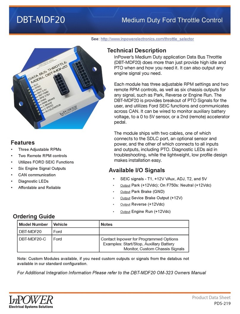
Model SBF90
Eight Lamp School Bus
Electronic Flasher
Introduction
The Model SBF90 flasher/controller is a completely electronic microprocessor
based device dedicated to the school bus warning light application. It is com-
prised of a logic controller and a unique and highly efficient power switching
circuit. The SBF90 operates the stop arm solenoid and eight 80 watt warning
lamps. Inputs from the Start Switch and Passenger Door Switch activate the
flasher/controller. Master Switch and Override Switch provisions are also
included. Capabilities for both Sequential and Non-Sequential operation are
provided.
The Model SBF90 flasher’s circuitry is sealed to protect against severe
environments and its internal construction is designed to withstand shock and
vibration typically found in school bus applications. Wiring connections to the unit
are via industry standard 0.25 inch Faston terminals.
Installation
The SBF90 should be located in a dry area such as the electrical compartment of
the school bus. It should be accessible to the lamp wiring, 12 volt power, and
ground. Mount the flasher on a clean, smooth metal surface to ensure the most
effective heat transfer (the mounting plate removes heat from the flasher).
Before wiring the flasher/controller, disconnect the 12 volt power from the
chassis by removing the battery connection.
Wire the flasher/controller to the required lights, ground, power and other devices
as shown in the Wiring Diagrams and Technical Description sections. Ensure that
the power wiring to the flasher/controller is fused. The fuse and wire size must be
of sufficient size to protect the wiring and prevent from false tripping due to the
lamp loads and high inrush currents. It is very important to provide a good ground
to the unit. The wiring harness connecting to the flasher should be properly
secured to prevent damage from vibration and stress on the connections.
OWNERS MANUAL

23
Figure 1 Wiring Diagram - Eight Lamp Sequential Operation
Right Amber
Right Red
Left Red
Left Amber
Master Switch
Start Switch
Door Switch
+12V
Fuse
Override Switch
+12 V
Note - If Stop Arm
exceeds 3 amps
use relay circuit.
Coil
+12V
Relay Circuit
Pin 5
+12 V
Sequence Of Operation
1. Start Switch is activated (momentary contact).
2. Amber lights start flashing (alternately).
3. Door Switch closes. Amber lights stop.
4. Red lights start flashing and stop arm is actuated.
5. Door Switch opens, red lights stop flashing and stop arm is retracted.
Note - Anytime Override Switch is closed red lights
start flashing immediately.
Figure 2 Wiring Diagram - Eight Lamp Non-Sequential Operation
Right Amber
Right Red
Left Red
Left Amber
Master Switch
Start Switch
Door Switch
+12V
Fuse
Override Switch
+12 V
Note - If Stop Arm exceeds
3 amps use relay circuit.
Relay Circuit
+12V
Coil
Pin 5
+12 V
Sequence Of Operation
1. Start Switch is activated (momentary contact).
2. Amber lights start flashing (alternately).
3. Door Switch closes.
4. Amber lights stop and red lights start flashing.
5. Door Switch opens, red lights stop flashing.
Note - Anytime the Door Switch or Override Switch
is closed red lights start flashing immediately.
Figure 3 Wiring Diagram - Four Lamp Sequential Operation
Right Front
Right Rear
Left Front
Left Rear
Master Switch
Start Switch
Door Switch
+12V
Fuse
Override Switch
+12 V
+12V
Coil
+12 V
Sequence Of Operation
1. Start Switch is activated (momentary contact).
2. Red lights start flashing (alternately).
3. Door Switch closes.
4. Stop Arm is actuated and red lights continue to flash.
5. Door Switch opens, red lights stop flashing and
Stop Arm is retracted.
Note - Anytime Override Switch is closed red lights
start flashing immediately but Stop Arm only actuates
when Door Switch is actuated.
Specifications
Operating Voltage: 8 to 16 Volts DC
Output Current Rating
Lamps (Pins 3, 4, 6, & 7): 16 amps
Stop Arm (Pin 5): 3 amps
Operating Temperature: -40°C to +85°C
Storage Temperature: -50°C to +85°C
Terminals: 0.250 Inch Faston (11 total)
Mechanical Drawing
All dimensions in inches.
Fuse
Fuse
Fuse
InPOWERInPOWER
the systems people
Model SBF90
Eight Lamp School Bus
Electronic Flasher/Controller
Model SBF90
Eight Lamp School Bus
Electronic Flasher/Controller
InPOWER LLC
Galena, Ohio
(866)548-0965
www.InPowerDirect.com
InPOWER LLC
Galena, Ohio
(866)548-0965
www.InPowerDirect.com
InPOWERInPOWER
the systems people
Model SBF90
Eight Lamp School Bus
Electronic Flasher/Controller
Model SBF90
Eight Lamp School Bus
Electronic Flasher/Controller
InPOWER LLC
Galena, Ohio
(866)548-0965
www.InPowerDirect.com
InPOWER LLC
Galena, Ohio
(866)548-0965
www.InPowerDirect.com
InPOWERInPOWER
the systems people
Model SBF90
Eight Lamp School Bus
Electronic Flasher/Controller
Model SBF90
Eight Lamp School Bus
Electronic Flasher/Controller
InPOWER LLC
Galena, Ohio
(866)548-0965
www.InPowerDirect.com
InPOWER LLC
Galena, Ohio
(866)548-0965
www.InPowerDirect.com
0.250 6.00
6.50 0.256
0.875
1.00
0.175 x 0.250
Stop
Arm
Stop
Arm
Stop
Arm
Stop
Arm
Stop
Arm
0.250 Inch
Faston Terminals
1
2
3
4
5
6
7
8
9
10
11
1- Override
2 - Master
3 - Right Amber
4 - Right Red
5 - Stop Arm
6 - Left Red
7 - Left Amber
9 - FRAA
10 - FR
11 - Ground
8 - Start
1 - Override
2 - Master
3 - Right Amber
4 - Right Red
5 - Stop Arm
6 - Left Red
7 - Left Amber
9 - FRAA
10 - FR
11 - Ground
8 - Start
1- Override
2 - Master
3 - Right Amber
4 - Right Red
5 - Stop Arm
6 - Left Red
7 - Left Amber
9 - FRAA
10 - FR
11 - Ground
8 - Start
Model SBF90
Eight Lamp School Bus
Electronic Flasher/Controller
InPOWER
the systems people
InPOWER LLC
Galena, Ohio
(866)548-0965
www.InPowerDirect.com
Ground FR FRAA Start Amber Red
Left
Stop Arm
Red Amber
Right
Master Override

4
InPOWER LLC
3555 Africa Road
Galena, Ohio 43021
Tel 740-548-0965 Fax 740-548-2302
www.InPowerDirect.com
OM04h-031116 (p/n 8601.004A) Copyright 2003, InPower LLC. Specifications subject to change without notice.
Technical Description
Override Switch (Pin 1- Override)
An override switch may be used to function as a backup device as well as a means to
immediately start the red lights flashing, bypassing the door switch and start button. The
+12 volt power must be adequately fused. The override switch requires two contacts, one
for Pin 1 and the second for Pin 10.
Master Switch (Pin 2 - Master)
This is the input for the 12 volt power, and must be adequately fused.
Right Amber Lights (Pin 3 - Right Amber)
This output provides the +12 volt power to flash the right front and right rear amber lights at
a rate of 75 flashes per minute at a 50% duty cycle.
Right Red Lights (Pin 4 - Right Red)
This output provides the +12 volt power to flash the right front and right rear red lights at a
rate of 75 flashes per minute at a 50% duty cycle.
Stop Arm (Pin 5 - Stop Arm)
This output supplies +12 volt power to actuate the stop arm device(s) when the red lights
operate. If the load is more than 3 amps a relay circuit should be used (see Wiring
Diagrams). Four lamp applications require different wiring (see Figure 3).
Left Red Lights (Pin 6 - Left Red)
This output provides the +12 volt power to flash the left front and left rear red lights at a rate
of 75 flashes per minute at a 50% duty cycle.
Left Amber Lights (Pin 7 - Left Amber)
This output provides the +12 volt power to flash the left front and left rear amber lights at a
rate of 75 flashes per minute at a 50% duty cycle.
Start Switch (Pin 8 - Start)
This input is from a momentary contact closure that supplies +12 volts to start the flash
sequence.
Flash Red ONLY After Amber (Pin 9 - FRAA)
This grounded input from the door switch will cause the red lights to flash after the start
switch is activated and the amber lights are flashing.
Flash Red When Door is Opened (Pin 10 - FR)
This grounded input from the door switch will cause the red lights to flash anytime the door
is opened (non-sequential operation).
Ground (Pin 11 - Ground)
Logic and power ground for the flasher/controller unit. This must be a good quality ground
connection.
InPower wants to ensure total customer
satisfaction. Please download a product
evaluation form at www.InPowerDirect.com/
customer_evaluation.htm or call us toll free
at 866-548-0965 to be sent a form by mail.
C
Warranty
InPOWER LLC warrants its products to be free from defects in material and workmanship
under normal use, care and maintenance for a period of two (2) years from the date of
shipment. Please see www.inpowerdirect.com/warranty.htm for specifics or call 866-548-
0965 for a copy of our warranty policy.
Other InPOWER Controllers manuals

