InPOWER DBT-MDF20 User manual
DBT-MDF20 Owner’s Manual
Document: OM-232 Version Code:
Date: Jan 24, 2020 Date:
© Copyright 2020 InPower LLC
Page
1 of 14
InPower LLC
8311 Green Meadows Drive
Lewis Center, Ohio 43035 USA
740-548-0965
www.InPowerLLC.com
OWNERS MANUAL
InPower Model DBT-MDF20
Contents
1. Introduction............................................................ 2
2. Installation Procedures.......................................... 3
3. Operation............................................................... 7
4. Mechanical Drawing .............................................. 9
5. Status LED and Troubleshooting........................... 10
6. Contact Information ............................................... 12
Electronic Throttle Module and Databus Decoder
for Ford 2020+ Vehicles
See: http://www.inpowerelectronics.com/throttle_selector

DBT-MDF20 Owner’s Manual
Document: OM-232 Version Code:
Date: Jan 24, 2020 Date:
© Copyright 2020 InPower LLC
Page
2 of 14
InPower LLC
8311 Green Meadows Drive
Lewis Center, Ohio 43035 USA
740-548-0965
www.InPowerLLC.com
1. Introduction
InPower’s DBT-MDF20 Data Bus Throttle both decodes the vehicle data bus
to provide you with the signals you need and provides high idle engine RPM
and PTO control. This product is compatible with 2020+ Ford trucks and vans
equipped with the Ford Stationary Elevated Idle Control (SEIC).
Modules come with four modes of high idle control: one standby mode, two
preset RPM modes, and one variable input RPM mode based on a customer-
supplied remote variable resistor. The standard module also includes four data
bus signal outputs: Park Brake Set, Reverse, Engine Run and Park (note: on
F750 chassis, the output is Neutral) with the capability of additional or alternate
outputs per customer special request. InPower Contact information is located
on the back page of this manual.
Note: The data bus signal outputs will continue to function so long as
the unit has power and vehicle ignition is in the run position. However,
the throttle functions will only operate if the Chassis Ready Conditions
are satised. LED diagnostic indicators are provided to aid in system
troubleshooting. These LEDs are located on the module opposite the
connectors.
Chassis Ready Conditions typically could be:
• No vehicle speed
• Accelerator not depressed
• Engine up to Operating Temperature
• Service brake not depressed
• Engine running and below 1,000 RPM
• No Diagnostic Trouble Code (DTC). Check Engine light must be off.
• Other hindering conditions will be detailed in the Body Builder’s Guide
(www.eet.ford.com/truckbbas/)
The DBT-MDF20 kit includes two cables. The rst cable (J1 Harness) connects
to the module via connector J1 and has three labeled sets of 20-inch blunt
cut wires: ve wires for SEIC, ve wires for inputs, and six wires for data bus
signal outputs. The second cable (J2 Harness) connects to the module via
connector J2 and has a 24 Pin SDLC Gateway connector and a set of seven
blunt cut wires for remote high idle control and preset RPM adjustments. This
Y-harness goes in place of the SDLC Gateway Plug where it plugs into the
back of the SDLC Gateway (See Section 2.4). Likewise the SDLC Gateway
Plug that plugged into the Gateway now should plug into the other connector in
the SDLC Gateway T-Harness.
Note:Ford vehicle wire colors and locations may vary substantially
between different models and even different model years. Please obtain
and consult the SEIC information for your specic vehicle prior to
installing the module. Documentation may be obtained from Ford’s
Truck Body Builder Advisory Service:
www.eet.ford.com/truckbbas/

DBT-MDF20 Owner’s Manual
Document: OM-232 Version Code:
Date: Jan 24, 2020 Date:
© Copyright 2020 InPower LLC
Page
3 of 14
InPower LLC
8311 Green Meadows Drive
Lewis Center, Ohio 43035 USA
740-548-0965
www.InPowerLLC.com
2. Installation Procedures
WARNING
!
2.1 Safety Precautions
This electronic throttle product has been designed and manufactured to meet
the intended application requirements and specications. Any modications
to the product or to the installation procedure can be dangerous and will void
InPower’s warranty.
• Read and understand the instructions in this manual and other manuals
before starting the installation.
• Make sure that the vehicle battery power is disconnected during
installation of the throttle module.
• Reconnect the battery when the system installation is complete.
• Wear appropriate safety equipment, such as protective eyeglasses,
faceshield and clothing when installing equipment and handling the
battery.
• Be careful when working near a battery. Make sure that the area is
well ventilated and that there are no ames near the battery. Never lay
objects on the battery that can short the terminals together. If battery acid
gets in your eyes, immediately seek rst aid. If acid gets on your skin,
immediately wash it off with soap and water.
• Avoid disconnecting the Gateway Connector when the vehicle is powered
since that will result in a Fault Code being generated.
2.2 Getting Started
IMPORTANT NOTE: Once again! Please obtain the specic SEIC
installation instructions for your vehicle make and model from Ford. Wire
colors and locations may vary from model to model and even between
different years for the same model. The guide may be obtained from
Ford’s Body Builder Advisory Service.
(www.eet.ford.com/truckbbas/)
We recommend installing the DBT-MDF20 system under the dash near the
SDLC Gateway due to the proximity of the wiring connections and cable
length. The unit should not be located in the engine compartment or any other
location that is not protected.
You will need tools to splice wires together. For each xed preset mode,
you will need a a switch for selecting the Preset. It is possible to combine
the Presets in a three position Center Off switch. For Variable RPM control,
you will need a potentiometer. We recommend a 10 Kohm 3, 5, or 10-turn
potentiometer such as those available from Digikey.
Do not lengthen the cable from the module to the SDLC Gateway Y Harness.
Carefully disconnect the battery before making any electrical connections.
DBT-MDF20 Owner’s Manual
Document: OM-232 Version Code:
Date: Jan 24, 2020 Date:
© Copyright 2020 InPower LLC
Page
4 of 14
InPower LLC
8311 Green Meadows Drive
Lewis Center, Ohio 43035 USA
740-548-0965
www.InPowerLLC.com
2.3 Mounting
Mount the DBT-MDF20 module under the dash or on a at surface using the
two mounting holes. Ensure that you have sufcient distance to install the 36
inch SDLC Gateway Y cable that is part of the J2 harness.
Plug the J1 cable into the J1 connector (16 pin connector) and plug the J2
cable into the J2 connector (12 pin connector). The J2 cable will be used
for the SDLC Y Gateway Connector, power input, and the remote RPM
potenitometer (Accelerator) adjustment. The J1 cable will be used for
hooking into the SEIC circuit, high idle on/off or mode select switches and for
providing output signals.
2.4 Wiring
Ensure the J1 cable and the J2 cables are both connected to the module.
Note: If the vehicle is on and the unit has power, even if the Preset RPM
functions are not engaged, the Databus Decoder signals will continue to
operate. If the Databus Decoder signals will not be used, properly secure
the Output wire group on the J1 harness.
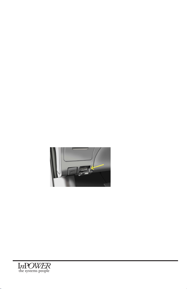
A. Connecting the DBT-MDF20 to the Chassis
The Ford SDLC Gateway is the device which now provides the OBDII port for
the customer, and is located in the same location as the conventional location
for the OBDII port (Driver’s side (Left)) under the Dash. The SDLC Y Harness
Plug inserts into the SDLC Gateway connector on the back side of the Ford
SDLC Gateway. The Ford SDLC Gateway provides security for data requests
from the Secure Data OBDII data bus connection to the outside world.
To connect the DBT-MDF20 to the system, unplug the SDLC Gateway to
Chassis connector from the back of the SDLC Gateway, and Plug P2 of the
DBT-MDF20 SDLC Y-Harness into the Gateway where the Gateway cable
connector was previously. Then connect the Gateway to Chassis Connector
into P1 connector. This will provide access to Chassis GND and Chassis
Data.

DBT-MDF20 Owner’s Manual
Document: OM-232 Version Code:
Date: Jan 24, 2020 Date:
© Copyright 2020 InPower LLC
Page
5 of 14
InPower LLC
8311 Green Meadows Drive
Lewis Center, Ohio 43035 USA
740-548-0965
www.InPowerLLC.com
Side Back
SDLC
Gateway
Connector
Front Side
Secure
OBDII Con-
nector
Under Dash
Mounting
SDLC Ford Gateway
DBT-MDF20 SDLC
Harness
DBT-MDF20
Y Part of Harness
Secure OBDII
Connector
Harness SDLC
Gateway Connector
SDLC Gateway
Connector
To Chassis
P1
P2
DBT-MDF20 SDLC
Throttle Harness
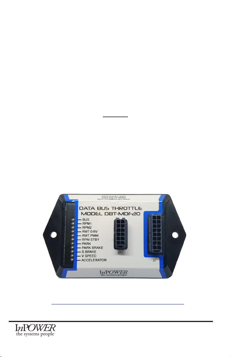
J1
P2
J1
J2
www.InPowerLLC.com
Made in the USA
LOT:1234567890
Diagnostic
LEDs
- Bus
- RPM1
- RPM2
- RMT 0-5V
- RMT PWM
- RPM STBY
- PARK
- PARKBRAKE
- S BRAKE
- V SPEED
- ACCELERATOR
DATA BUS THROTTLE
MODEL DBT-MDF20
Chassis Data Bus
Group 1 SEIC
Group 2 Inputs
Group 3 Outputs
DBT-MD I/O Harness
P1
J2
P3
RPM Adj, Remote
RPM/PWM, etc
Secure Data
OBDII
Connector
Ford
SDLC
Gateway
Chassis Data Buses
Connector
B. SEIC
Locate the Group 1 SEIC of blunt cut wires on the J1 harness. Install wires
between the blunt cut wires provided on the J1 harness and the respective
inputs and outputs of the Ford SEIC as shown in the wiring diagrams.
C. High Idle Mode Selection Controls
Determine the combination of high idle speed modes needed (standby high
idle, variable RPM control and/or up to two additional xed preset speeds).
The customer needs to supply a switch (or switches) for turning for selecting
the RPM1 and/or RPM2 modes, and for the Remote variable RPM, needs
to provide a 0 to 5V potentiometer. We recommend a three to ten-turn
potentiometer such as those found at Digikey and other similar vendors.
Alternatively this could be a 0-5V Accelerator Pedal.
Please refer to Section 2.6 for a complete chart of input and output wires. All
mode selection switches should be wired to the INPUTS wire group in the J1
Harness. The variable remote accelerator or potentiometer (if used) should be
wired to the appropriate wires in the J2 Harness.

DBT-MDF20 Owner’s Manual
Document: OM-232 Version Code:
Date: Jan 24, 2020 Date:
© Copyright 2020 InPower LLC
Page
6 of 14
InPower LLC
8311 Green Meadows Drive
Lewis Center, Ohio 43035 USA
740-548-0965
www.InPowerLLC.com
D. Decoded Data Bus Signal outputs
Note: As long as the unit has power (connected via the Red wire on the J2
harness) and the vehicle is on (data bus signals are not transmitted when the
vehicle is off), the DBT-MDF20 will provide these output signals, regardless of
the status of the throttle controls and engine RPM.
All decoded signal output wires are located in the J1 harness in the bundle
marked Group 3 Outputs. Each wire corresponds to a different signal and all
wires give a 600mA current when connected. (Note: The pink wire and the
gray wire are unused in the standard model but may be given a custom signal
at customer request.) Tape or otherwise properly secure any unused wires
out.
Please see Section 2.6 for chart.
2.5 Adjusting Values of RPM settings
All four RPM modes (RPM1, RPM2, RPM Remote Variable, and RPM
Standby) come with Factory Calibrations but may be adjusted by the user if
so desired once the module is installed.
1. Activate the mode desired for adjustment by connecting the
corresponding line (Input RPM1, RPM2, RPM Remote, or RPM Stdby)
to +12V. Note: If the Remote Variable Accelerator RPM mode is
activated (Connector Pin 7 - Dark Blue), this process will adjust the
Maximum RPM setting.
2. Locate the grey wire (Pin 9) in the J2 harness. Apply +12V to this wire
to raise the RPM or ground the wire to lower it to the desired RPM.
For each second that +12V is connected to the RPM Adjust wire (Pin
9), the RPM will increase by 50 RPM per second. Likewise, if the
RPM Adjust wire is tied to GND, the RPM will decrease at a rate of 50
RPM per second. Releasing it from either +12V or Ground will steady
the RPM.
For each bump of less than a half second, the RPM will move by 25RPM up or
down (depending on whether Adjust is bumped to +12V or GND). If connected
to +12V or GND for a second (or more) it will increase by 50RPM for each
second the Adjust is connected to the voltage.
3. To permanently store the changed RPM, disconnect from all Input
RPM Mode lines but maintain power to the unit (powered by the
Ignition Key Switch). If you disconnect the power without rst
deactivating all modes, it will not store the changed values.
Note 1: An alternative to disconnecting the RPM Mode selection lines is to
simply trip one of the interlocks, for example, stepping on the Service Brake
(or Accelerator) for 10 Seconds will trip that interlock and store the value. For
the rst 5 seconds of the Interlock tripping, the associated LED will Flash and
shut down the Throttle Controller (storing the new RPM value). After that, the
Controller will restart, and it will re-read all the inputs (including Data Bus) and
update the state of the Controller based on all it’s inputs.
Note 2: A minimum of 910 RPM is recommended for PTO to activate, so we do
not recommend lowering the Standby RPM.

DBT-MDF20 Owner’s Manual
Document: OM-232 Version Code:
Date: Jan 24, 2020 Date:
© Copyright 2020 InPower LLC
Page
7 of 14
InPower LLC
8311 Green Meadows Drive
Lewis Center, Ohio 43035 USA
740-548-0965
www.InPowerLLC.com
J1 Harness
Group 1
SEIC
Wire
Color
Connector
Pin #
Description
White 2 Input from PTO Relay/PTO
Brown 8 Input from PTO VREF
Orange 13 Output to PTO-REQ2 (Not Used - Do not Connect!)
Except used on Older Gas
Yellow 14 Output to PTO-REQ1
Green 16 Output to PTO-RPM
Group 2
Inputs
Wire
Color
Connector
Pin #
Function
Brown 3 Not Used (Low2)
Pink 4 Input RPM1 (High1) Overrides RPM2, RPM STBY, RPM Remote
Tan 5 Input RPM2 (High2) Overrides STBY and Remote RPM
Violet 6 Input RPM STBY (High3) Lowest Priority
Dark Blue 7 Input RPM Remote (High4) Overrides RPM STBY
Group 3
Outputs
Wire Color Connector
Pin #
Function Signal Output Level
Dark Green 1 Park Brake Set Ground (Out Low2)
Pink 9 Not Used Not Used (Out High 6)
Tan 10 Veh. In Reverse Positive (Out High 6)
Violet 11 Engine Run Positive (Out High 6)
Dark Blue 12 Park (750: Neutral) Positive (Out High 6)
Gray 15 Not Used Ground (Out Low 1)
J2 Harness
Wire
Color
Connector
Pin #
Function Comments
Black 1 Ground Gateway Connector
Black 2 Ground Out to Remote Accelera-
tor Control Blunt Cut *
Orange 3 Input From 0-5V (T1) Blunt Cut *
Red 7 +12V Power Input Blunt Cut
Violet 8 Not Used (VAux) Blunt Cut
Gray 9 RPM Adjust Blunt Cut
Pink 10 Input (T2) Not Used Blunt Cut
White 11 5V Output to Remote Blunt Cut *
2.6 Harness Wires
*These three wires are for use with remote variable RPM
Note: J2 gray wire may be used to adjust calibration for all RPM settings (See section 2.5)

DBT-MDF20 Owner’s Manual
Document: OM-232 Version Code:
Date: Jan 24, 2020 Date:
© Copyright 2020 InPower LLC
Page
8 of 14
InPower LLC
8311 Green Meadows Drive
Lewis Center, Ohio 43035 USA
740-548-0965
www.InPowerLLC.com
3. Operation
When the vehicle is parked and Chassis Ready Conditions are satised, the
engine idle speed may be controlled by selection of one of the four available
modes: RPM1, RPM2, a variable RPM, and Standby RPM. The preset RPM
modes may be adjusted via applying +12V or GND to the grey RPM Adjust
wire (see 2.5 Adjusting Values of RPM Settings, page 6).
Chassis Ready Conditions:
• No vehicle speed
• Parking brake set
• Shift selector in Park (or Neutral on F750)
• Accelerator not pressed
• Service brake not pressed
• Engine running and below 1000 RPM
• No Diagnostic Trouble Code (DTC). Check Engine light must be off.
NOTE: While the engine is in high idle, should the throttle be deactivated
by one of the Chassis Ready Conditions changing, the engine will return
to normal speed. The throttle will ash the diagnostic LEDs to indicate the
cause of the deactivation for ve seconds after Chassis Ready Conditions
are restored. Then it will reset and return the vehicle to high idle.
Modes of Operation:
Standby Mode
Function: Increase idle to minimum required to activate PTO
Activation: Apply +12V to Violet Wire on J1 Harness Input Group
Factory Calibration: 950 RPM
NOTE: A minimum of 910 RPM is required to enable PTO on 2020+
vehicles, so we do not recommend adjusting the Standby set-point below
the Factory Calibration.
Preset RPM Modes
Function: Increase idle to preset RPM values
Activation: RPM1: Apply +12 V to Pink Wire on J1 Input Group
RPM2: Apply +12V to Tan Wire on J1 Input Group
Factory Calibration: RPM1: 1500 RPM RPM2: 1200 RPM
Calibration Range: Varies based on vehicle model. Generally, 900 RPM
to 2200 RPM (gas) or 2800 RPM (diesel)
Variable RPM Mode
Function: Varies RPM as a function of voltage from customer-supplied
remote variable control

DBT-MDF20 Owner’s Manual
Document: OM-232 Version Code:
Date: Jan 24, 2020 Date:
© Copyright 2020 InPower LLC
Page
9 of 14
InPower LLC
8311 Green Meadows Drive
Lewis Center, Ohio 43035 USA
740-548-0965
www.InPowerLLC.com
Activation and Adjustment:
+5V
GND
Pin 11 White
ADJ
Pin 3 Orange
Wiper of
Potentiometer
Pin 2 Black
Remote Control for Accelerator
or Remote Accelerator Pedal
10 turn Potentiometer 10Kohms
1. Activate Standby Mode: Apply +12V to Pink Wire on J1 Harness Input
Group (J1 Pin4)
2. Activate Remote Mode: Apply +12V to Dark Blue Wire on J1 Harness
Input Group (J1 Pin7)
The module will then look for a signal from the remote potentiometer.
The RMT 0-5V (and RPM-PWM LED) will ash until it receives a
remote signal. At that point, the corresponding Remote 0-5V LED will
turn solid (RPM-PWM should turn OFF).
3. To adjust RPM with the potentiometer, start at zero and then turn
potentiometer up slowly until desired RPM is reached.
Minimum RPM: Equal to Standby Mode RPM
Maximum RPM: Preset Adjustable. Factory Default: 1500 RPM
Mode Priorities:
If more than one mode is selected at a time, the modes take the following
priorities:
RPM1 Highest - overrides all other modes
RPM2 Second - overrides lower modes
Variable RPM Third - overrides lower mode
Standby Lowest
Note: The one with the highest priority will over rule the lower priority settings.
There are no restrictions if multiple modes are egaged simulaneously, for
instance if Standby is engaged with RPM1 at the same time. If this is the
case, then since it is a higher priority, RPM1 will engage. So in this way,
Multiple modes can be requested at once with no problem with interference.
DBT-MDF20 Owner’s Manual
Document: OM-232 Version Code:
Date: Jan 24, 2020 Date:
© Copyright 2020 InPower LLC
Page
10 of 14
InPower LLC
8311 Green Meadows Drive
Lewis Center, Ohio 43035 USA
740-548-0965
www.InPowerLLC.com
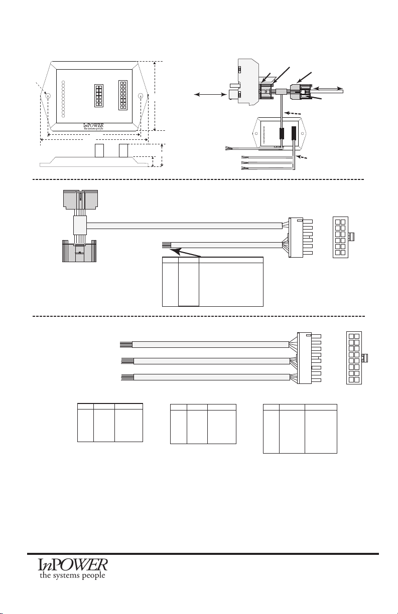
4. Mechanical Drawing
DBT-MD I/O Harness
Secure Data OBDII
Connector
Ford
SDLC
Gateway
On
Truck
J1
J2
www.InPowerLLC.com
Made in the USA
LOT:1234567890
Diagnostic
LEDs
- Bus
- RPM1
- RPM2
- RMT 0-5V
- RMT PWM
- RPM STBY
- PARK
- PARK BRAKE
- S BRAKE
- V SPEED
- ACCELERATOR
DATA BUS THROTTLE
MODEL DBT-MDF20
3.8”
4.4”
2.6”
0.2” dia
0.8”
0.4”
DBT-MDF20 SDLC
Throttle Harness
P1
P2
J1
J2
www.InPowerLLC.com
Madein the USA
LOT:1234567890
Diagnostic
LEDs
- Bus
- RPM1
- RPM2
- RMT 0-5V
- RMT PWM
- RPM STBY
- PARK
- PARKBRAKE
- S BRAKE
-V SPEED
- ACCELERATOR
DATA BUS THROTTLE
MODEL DBT-MDF20
Gateway to Chassis
Group 1
Group 2
Group 3
DBT-MD I/O Harness
SDLC
Gateway
Connector
Original SDLC
Gateway Plug
SDLC Y
Harness Plug SDLC Y Harness
Connector
RPM Adj
Remote RPM
etc
P1
P2
J2
J1
DBT-MDF20 SDLC Throttle Harness Sensors and Power
P3 Color Signal
Pin2 Black GND for Remote Accel Pedal
Pin3 Orange T1
Pin7 Red +12V
Pin8 Violet VAux
Pin9 Gray ADJ
Pin10 Pink T2
Pin11 White 5V
1
2
3
4
5
6
7
8
9
10
11
12
1
2
3
4
5
6
7
8
9
10
11
12
13
14
15
16
P1 Color Signal
Pin2 White PTO-Relay
Pin8 Brown PTO-Vref
Pin13 Orange PTO-Req2
Pin14 Violet PTO-Req1
Pin16 Gray PTO RPM
GROUP 1 - SEIC
P1 Color Signal
Pin3 Brown In Low 2
Pin4 Pink In High 1
Pin5 Tan In High 2
Pin6 Violet In High 3
Pin7 Dk Blue In High 4
GROUP 2 - Inputs
P1 Color Signal
Pin1 Dk Green Out Low 2
Pin9 Pink Out High 6
Pin10 Tan Out High 4
Pin11 Violet Out High 5
Pin12 Dk Blue Out High 3
Pin15 Gray Out Low 1
GROUP 3 - Outputs
GROUP 1 - SEIC
GROUP 2 - Inputs
GROUP 3 - Outputs

DBT-MDF20 Owner’s Manual
Document: OM-232 Version Code:
Date: Jan 24, 2020 Date:
© Copyright 2020 InPower LLC
Page
11 of 14
InPower LLC
8311 Green Meadows Drive
Lewis Center, Ohio 43035 USA
740-548-0965
www.InPowerLLC.com
5. Status Indicators and Troubleshooting
5.1 For new installations. The throttle automatically checks to see if its software
revision code supports the chassis. The DBT-MD detects the vehicle type during
the rst ignition turn-on after installation. If the Park LED is on solid and all other
LEDs are off, the truck is not supported by this model.
Please refer to the Throttle Selector Guide found on our website for the most up-to-
date compatibility information.
(www.inpowerdirect.com/electronicthrottlecontrols_selector.php)
5.2 Check all wiring and make sure all connectors are plugged in rmly.
Refer to the Harness Wire Chart in section 2.5 on page 5 when checking that wires
are connected to appropriate inputs and outputs.
Ford vehicle wire colors and locations may vary substantially between different
models and even different model years. Please obtain and consult the SEIC
information for your specic vehicle. Documentation may be obtained from
Ford’s Truck Body Builder Advisory Service (www.eet.ford.com/truckbbas/).
5.3 A series of 11 LEDs on top of the module provide diagnostic information for
troubleshooting purposes. The LEDs are labeled and correspond to RPM modes,
Databus status and safety interlocks necessary to bring the vehicle to high idle. If
no LEDs are illuminated, the unit does not have power.
See LED Troubleshooting Flowchart on Page 13.
5.4 While engine is in high idle, if one of the Chassis Ready Conditions changes
states, the engine will return to factory idle. The throttle will ash the diagnostic
LEDs to indicate the cause of the high idle deactivation. Then, once conditions are
restored, after a ten second delay it will return the vehicle to the preset high idle
speed. This feature may be used to troubleshoot intermittent problems.
BUS
RPM1
RPM2
RMT 0-5V
RMT PWM
RMT STBY
PARK
PARK BRAKE
S BRAKE
V SPEED
ACCELERATOR
DBT-MD LED INDICATORS
DBT-MDF20 Owner’s Manual
Document: OM-232 Version Code:
Date: Jan 24, 2020 Date:
© Copyright 2020 InPower LLC
Page
12 of 14
InPower LLC
8311 Green Meadows Drive
Lewis Center, Ohio 43035 USA
740-548-0965
www.InPowerLLC.com
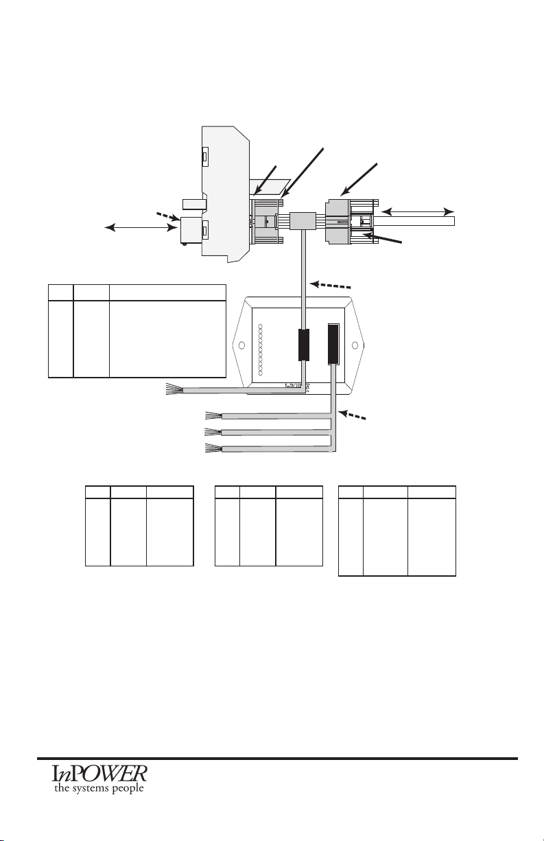
DBT-MDF20 SDLC
Throttle Harness
P1
P2
J1
J2
www.InPowerLLC.com
Made in the USA
LOT:1234567890
Diagnostic
LEDs
- Bus
- RPM1
- RPM2
- RMT 0-5V
- RMT PWM
- RPM STBY
- PARK
- PARK BRAKE
- S BRAKE
- V SPEED
- ACCELERATOR
DATA BUS THROTTLE
MODEL DBT-MDF20
Secure Data
OBDII
Connector
Gateway to Chassis
P1 Color Signal
Pin2 White PTO-Relay
Pin8 Brown PTO-Vref
Pin13 Orange PTO-Req2
Pin14 Yellow PTO-Req1
Pin16 Green PTO-RPM
Group 1 - SEIC
P1 Color Signal
Pin3 Brown In Low 2
Pin4 Pink In High 1
Pin5 Tan In High 2
Pin6 Violet In High 3
Pin7 Dk Blue In High 4
Group 2 - Inputs
P1 Color Signal
Pin1 Dk Green Out Low 2
Pin9 Pink Out High 6
Pin10 Tan Out High 4
Pin11 Violet Out High 5
Pin12 Dk Blue Out High 3
Pin15 Gray Out Low 1
Group 3 - Outputs
Group 1
Group 2
Group 3
DBT-MD I/O Harness
P3 Color Signal
Pin2 Black GND (Remote Variable Ctrl)
Pin3 Orange T1 (Remote Variable Ctrl)
Pin8 Violet VAux
Pin9 Gray ADJ
Pin10 Pink T2 - Not Used
Pin11 White 5V (Remote Variable Ctrl)
SDLC
Gateway
Connector
Original SDLC
Gateway Plug
SDLC Y
Harness Plug SDLC Y Harness
Connector
Ford
SDLC
Gateway
On
Truck
System Integration Diagram
DBT-MDF20 Owner’s Manual
Document: OM-232 Version Code:
Date: Jan 24, 2020 Date:
© Copyright 2020 InPower LLC
Page
13 of 14
InPower LLC
8311 Green Meadows Drive
Lewis Center, Ohio 43035 USA
740-548-0965
www.InPowerLLC.com
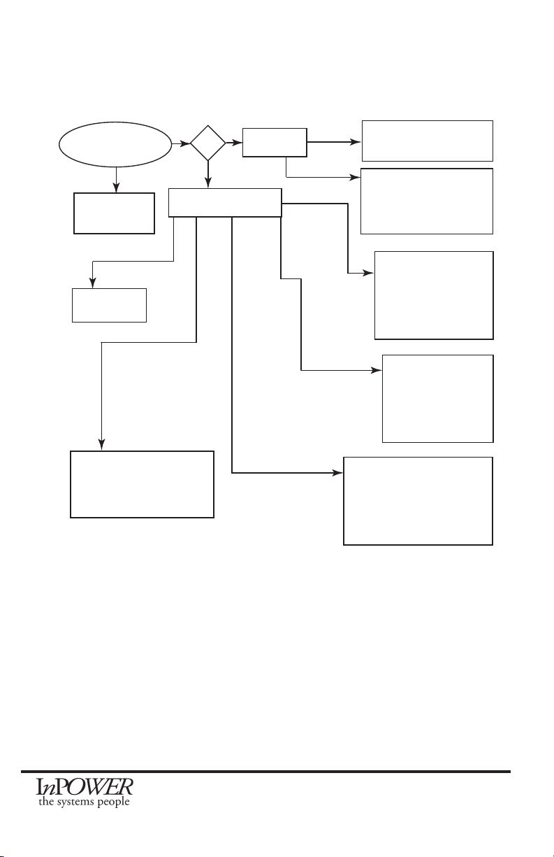
Are Any LEDs On?
Unit Has No
Power
No
Bus Only?
Solid
Flashing Unit Has Power but no
Databus RPM Message
Unit Has Power and
Databus RPM Message
Received, but no modes
selected
Yes
Mutiple LEDs Bus Solid
BUS On Single
Mode LED On Solid
Mode Activated -
Unit Working
Normally
Bus O RPM1
to RPM STBY
Flashing
A Second device is
connected to SEIC
wiring and is
controlling RPM
operation.
Bus On Mode
LED
Flashing.
One or more
Chassis Condi-
tion LED
Flashing
The Mode is selected.
Chassis Ready
Conditions not met.
Checking Flashing Interlock.
(e.g. if Park is Flashing make
certain vehicle is in Park).
Park On Solid
Truck Not
Supported
Bus On Solid RMT
0-5V Flash RMT,
RPM1,RPM2,STBY
o. All Others On
Solid
Operating at Standby
Speed, waiting on remote
input to control RPM
Flashing
Flashing
Flashing
5.5 LED Troubleshooting Flowchart

DBT-MDF20 Owner’s Manual
Document: OM-232 Version Code:
Date: Jan 24, 2020 Date:
© Copyright 2020 InPower LLC
Page
14 of 14
InPower LLC
8311 Green Meadows Drive
Lewis Center, Ohio 43035 USA
740-548-0965
www.InPowerLLC.com
Contact Us
InPower LLC
8311 Green Meadows Drive
Lewis Center, Ohio 43035
740-548-0965
www.InPowerLLC.com
Other manuals for DBT-MDF20
1
Other InPOWER Media Converter manuals


