InPOWER ABS3-200A User manual

Page
1 of 8
ABS3 Owner’s Manual
Document: OM-215 Version Code: B
Date: Jan 28, 2021 Date: Aug 9, 2021
InPower LLC
8311 Green Meadows Drive
Lewis Center, Ohio 43035 USA
740-548-0965
www.InPowerLLC.com
© Copyright 2021 InPower LLC
Chassis Battery
Loads
Chassis Battery
Alternator
Auxiliary Battery
Auxiliary Battery
Loads
InPower ABS3-200A
Auxiliary Battery Switch
1.0 Introduction
InPower’s ABS3 Series Auxiliary Battery Switch is next generation technology for ideal charging and
isolating an auxiliary battery from a vehicle’s chassis battery and alternator. This provides automatic
charging in either direction and also insures that the chassis battery will always be available for starting
the Vehicle. In addition there is a Manual mode where the chassis and auxiliary batteries are tied togeth-
er to provide additional starting power.
The ABS3 auxiliary battery switch uses InPower’s proven Patented solid-state contactor technology,
incorporating sophisticated microprocessor algorithms that include over-current, over-temperature, and
over and under-voltage sensing. The ABS3 will automatically reconnect if the faults are no longer pres-
ent. The ABS3 is available in 12V 200 Amp, 2 lug and 4 lug versions (ABS3-200A and ABS-200B) and a
12V, 300 Amp 4 lug version (ABS3-300).
INPUT
BAT 1 BAT 2
12V 200 AMP Auxiliary Battery Switch
LED
GND
www.InPowerLLC.com Lot Code
InPOWER
the systems people
ABS3-200A
7.0-18Vdc
INPUT
8.0-18Vdc
Patented
www.InPowerLLC.com/Patents
INPUT
BAT 1 BAT 2
LED
GND
12V 200 AMP Auxiliary Battery Switch
ABS3-200B
InPOWER
the systems people
Patented
www.InPowerLLC.com/Patents
www.InPowerLLC.com Lot Code
Electronic
Switch
INPUT
8.0-18Vdc
INPUT
BAT 1 BAT 2
LED
GND
12V 300 AMP Auxiliary Battery Switch
ABS3-300
InPOWER
the systems people
Patented
www.InPowerLLC.com/Patents
www.InPowerLLC.com Lot Code
Electronic
Switch
INPUT
8.0-18Vdc
7.0-18Vdc 7.0-18Vdc
ABS3 12V 200 Amp 2 Lug
ABS3 12V 200 Amp 4 Lug ABS3 12V 300 Amp 4 Lug
Electronic
Switch
OWNERS MANUAL
Solid State Auxiliary Battery Switch
ABS3-200A 12V 200 Amp, 2 Lug
ABS3-200B 12V 200 Amp, 4 Lug
ABS3-300 12V 300 Amp, 4 Lug

Page
2 of 8
ABS3 Owner’s Manual
Document: OM-215 Version Code: B
Date: Jan 28, 2021 Date: Aug 9, 2021
InPower LLC
8311 Green Meadows Drive
Lewis Center, Ohio 43035 USA
740-548-0965
www.InPowerLLC.com
© Copyright 2021 InPower LLC
2.0 Operation
In a system with the ABS3, the auxiliary battery is charged from the chassis battery and alternator, while the
chassis battery is protected from a total discharge, and therefore is available for starting the vehicle. As the
ABS3 is bidirectional, a charging device (such as a battery charger or gen-set connected to the auxiliary
battery) can also supply charging current to the chassis battery through the ABS3 while maintaining total
discharge isolation.
The ABS3 switch accomplishes it’s tasks through the constant monitoring of voltage and current by it’s
microprocessor controller. The proper time to transfer power in either direction between the chassis battery
and the auxiliary battery is based on a proprietary algorithm that utilizes both battery voltage and current
measurements. A “boost start” feature is provided that will allow the auxiliary battery to supply current to the
chassis battery to aid engine starting.
Since this is an intelligent switch monitoring voltage, current, and temperature, it is possible to accommodate
a wide variety of customer needs for operation, with programmable times, voltage and current settings. For
custom requirements, please contact InPower LLC directly for your needs.
LED shows whether the ABS3 is ON (LED ON) or OFF (LED OFF).
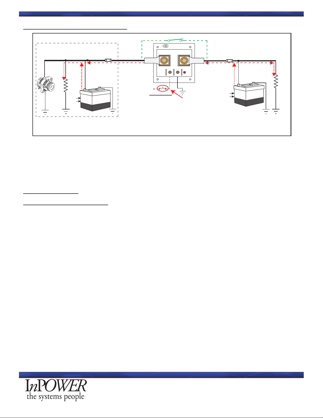
2.1 Normal Operation
Chassis
Battery
Alternator
Engine Compartment
InPower LLC
ABS3 Electronic
Auxiliary Battery Switch
Fuse *
Chassis
Loads
* SAE required wiring safety fuse. Not
supplied with ABS switch. SAE requires
within 18 inches of Battery.
Auxiliary
Loads
Aux
Battery
On
System Diagram with Charger
Boost Mode
12V
INPUT
BAT 1 BAT 2
12V 200 AMP Auxiliary Battery Switch
LED
GND
www.InPowerLLC.com Lot Code
InPOWER
the systems people
ABS3-200A
7.0-18Vdc
INPUT
8.0-18Vdc
Patented
www.InPowerLLC.com/Patents
Battery
Charger
13.2V
14.2A
Fuse *
Bi-Directional Mode
Conventional Current
Flow Depicted
Electronic
Switch
For normal operation, it is assumed that the engine is running and the alternator is supplying power to the
charge the chassis battery. When the chassis battery voltage (BAT 1) rises above 13.5 volts for 10 seconds,
the ABS3 closes and passes current to the BAT 2 side. This connects the two batteries to now charge the
auxiliary battery and power auxiliary loads.
Bidirectional Note: In the gure above, either the Alternator or the Battery Charger can charge the batteries
based on the charge requirement of either of the two batteries in the system. For the Battery Charger source,
the Auxiliary Battery becomes the Primary and the Chassis Battery becomes the Secondary Battery which the
ABS3 turns on to charge.
Over-current fault handling: If the ABS3 rated current is exceeded, the ABS3 will turn off after 1 second. If
no faults exist, the ABS3 will turn back on after 30 seconds
Automatic Operation:
• Module will automatically turn ON when battery voltage on either BAT 1 or BAT 2 is greater than
13.5Vdc for greater than 10 seconds.
• Module will automatically turn OFF when the battery voltages on BAT 1 and BAT 2 are less than
12.80Vdc for greater than 10 seconds.

Page
3 of 8
ABS3 Owner’s Manual
Document: OM-215 Version Code: B
Date: Jan 28, 2021 Date: Aug 9, 2021
InPower LLC
8311 Green Meadows Drive
Lewis Center, Ohio 43035 USA
740-548-0965
www.InPowerLLC.com
© Copyright 2021 InPower LLC
Manual Operation:
• Momentarily applying +12Vdc to INPUT terminal will cause the Module to turn ON if either BAT 1 and BAT
2 Voltage are at least 7.0Vdc as long as the voltage is present.
Voltage Requirements: The ABS3 switch requires one battery to be above 7.0 volts (in this case the chassis
battery) before it can close.
2.1.1 Charging Chassis and Aux from Alternator (Normal Operation)
Charge Mode
Chassis
Battery
Alternator
Engine Compartment
Fuse *
Chassis
Loads
* SAE required wiring safety fuse. Not
supplied with ABS switch. SAE requires
within 18 inches of Battery.
Aux
Loads
Aux
Battery
Fuse *
13.5 V
12.8 V
13.5 V
12.8 V
InPower LLC
ABS3 Electronic
Auxiliary Battery Switch
On
Boost Mode
12V
INPUT
BAT 1 BAT 2
12V 200 AMP Auxiliary Battery Switch
LED
GND
www.InPowerLLC.com Lot Code
InPOWER
the systems people
ABS3-200A
7.0-18Vdc
INPUT
8.0-18Vdc
Patented
www.InPowerLLC.com/Patents
Electronic
Switch
Conventional Current
Flow Depicted
When the engine is running and the alternator starts supplying current to the chassis battery and the chassis
battery voltage rises above 13.5 volts for 10 seconds, the InPower ABS3 switch will close connecting the two
batteries. The auxiliary battery will now recharge.
Note that the ABS switch requires one battery to be above 7.5 volts before it will close. If the ABS rated
current is exceeded (100% to 110%) for 1 second the ABS switch will turn off. It will automatically reset after
30 seconds if no faults are present.
2.1.2 Discharging (Normal Operation)
Discharge Mode
Chassis
Battery
Alternator
Engine Compartment
Fuse *
Chassis
Loads
* SAE required wiring safety fuse. Not
supplied with ABS switch. SAE requires
within 18 inches of Battery.
Aux
Loads
Aux
Battery
O
Fuse *
13.5 V
12.8 V
13.5 V
12.8 V
Conventional Current
Flow Depicted
InPower LLC
ABS3 Electronic
Auxiliary Battery Switch
Boost Mode
12V
INPUT
BAT 1 BAT 2
12V 200 AMP Auxiliary Battery Switch
LED
GND
www.InPowerLLC.com Lot Code
InPOWER
the systems people
ABS3-200A
7.0-18Vdc
INPUT
8.0-18Vdc
Patented
www.InPowerLLC.com/Patents
Electronic
Switch
If the engine is stopped, no alternator current is produced and the batteries begin to discharge. When the
voltage of the combined batteries drops below 12.8 volts for 10 seconds, the ABS3 switch will open, isolating
the auxiliary battery from the chassis battery to reserve engine starting capacity from the chassis battery.
Page
4 of 8
ABS3 Owner’s Manual
Document: OM-215 Version Code: B
Date: Jan 28, 2021 Date: Aug 9, 2021
InPower LLC
8311 Green Meadows Drive
Lewis Center, Ohio 43035 USA
740-548-0965
www.InPowerLLC.com
© Copyright 2021 InPower LLC
2.1.3 Boost Mode (Manual Control)
Chassis
Battery
Alternator
Engine Compartment
InPower LLC
ABS3 Electronic
Auxiliary Battery Switch
Fuse *
Chassis
Loads
* SAE required wiring safety fuse. Not
supplied with ABS switch. SAE requires
within 18 inches of Battery.
Aux
Loads
Aux
Battery
Boost Mode
(When 12V)
12V
Fuse *
13.5 V
12.8 V
13.5 V
12.8 V
Aux Boost Mode
Conventional Current
Flow Depicted
On
INPUT
BAT 1 BAT 2
12V 200 AMP Auxiliary Battery Switch
LED
GND
www.InPowerLLC.com Lot Code
InPOWER
the systems people
ABS3-200A
7.0-18Vdc
INPUT
8.0-18Vdc
Patented
www.InPowerLLC.com/Patents
In the event the chassis battery is discharged, the auxiliary battery may be used to supply current to the
chassis battery to aid engine starting. In this case, the Chassis Battery is in a discharged state, and the
Boost Start control input to the ABS3 is activated from a remote momentary switch. The ABS3 connects the
auxiliary battery to the chassis battery for the duration that the boost start switch is applied. Alternatively,
the “boost start” can be made automatic by connecting the input to the engine start signal.
3.0 Specications
3.1 Electrical Specications
Current Rating: 200 Amps (ABS3-200A/B) 300 Amps (ABS3-300)
Standby Current: 3.8 milliamps
Over-current Protection Trip: 205 Amps (+/- 2 Amps) for 1 sec (ABS3-200A/B)
305 Amps (+/- 2 Amps) for 1 sec (ABS3-300)
Operational Temperature Range: -40oto +185oF (-40oto +85oC)
Over-temperature Shutdown: > 185oF (> 85oC)
Operational Voltage Range: +7.0 to +18.0 Volts
Automatic Trip Voltages: ON if BAT1 or BAT2 > 13.5 for >10Sec
OFF if BAT1 or BAT2 < 12.8 for >10Sec
Manual Operation: ON if +12V to INPUT Terminal
(if BAT1 or BAT2 Volts > 7.0V)
Automatic Fault Reset: ABS3 will automatically restart in 30 sec (if no faults exist)
LED Indicator: Switch ON/OFF
INPUT Signal Voltage Range: +8.0 to 18.0 Volts (True)
Standby Current: <3.8mA
Environmental: Designed to IP67
Power Terminal Torque: Brass Bolts and Copper Washers supplied with ABS3 - 10 to 15 ft-lb
Input and Gnd Terminal Torque: 8/32 Screw Terminal with Brass Nuts (4 to 5 Inch Lbs)
Page
5 of 8
ABS3 Owner’s Manual
Document: OM-215 Version Code: B
Date: Jan 28, 2021 Date: Aug 9, 2021
InPower LLC
8311 Green Meadows Drive
Lewis Center, Ohio 43035 USA
740-548-0965
www.InPowerLLC.com
© Copyright 2021 InPower LLC
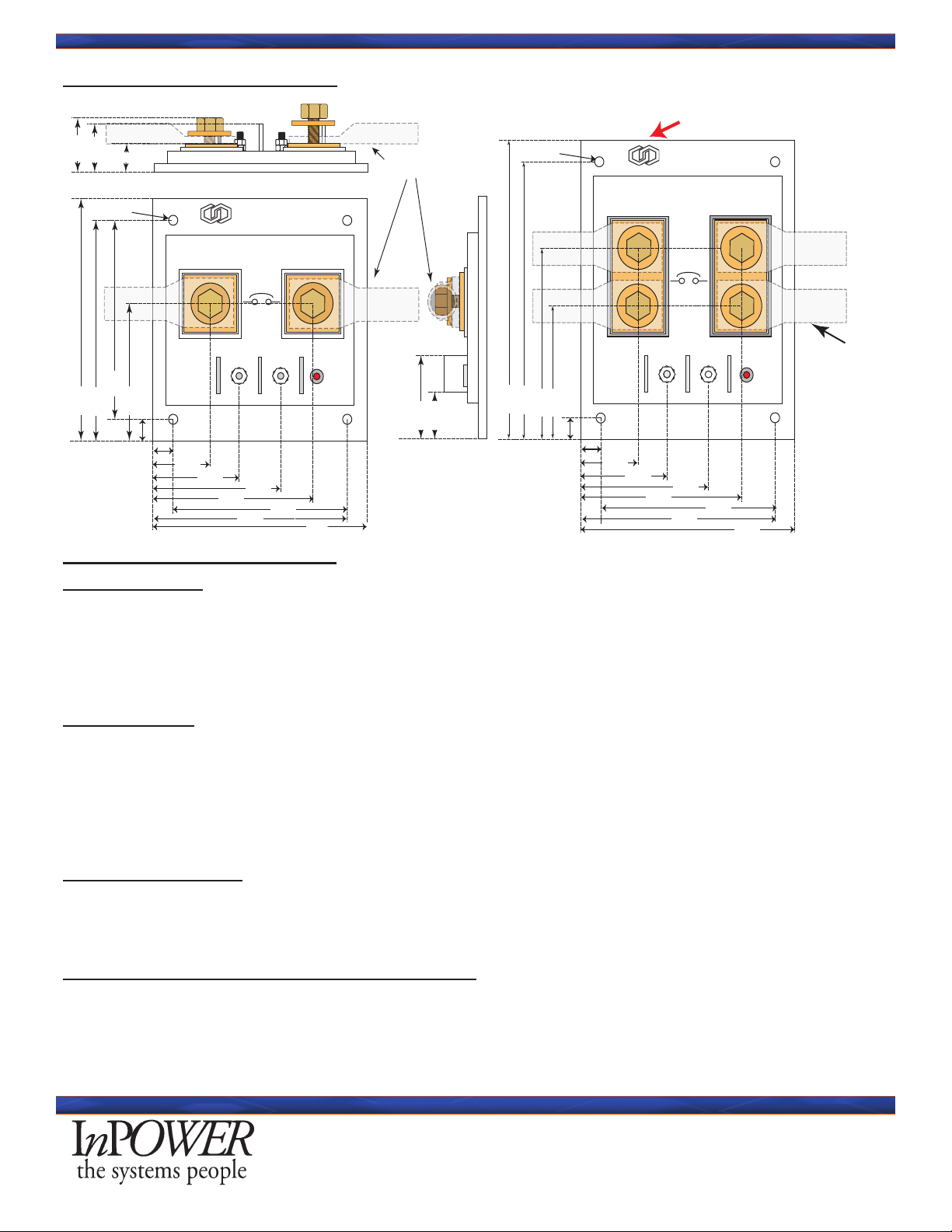
3.2 Mechanical Specications:
0.20
INPUT
BAT 1 BAT 2
12V 200 AMP Auxiliary Battery Switch
4.125
0.375
LED
GND
2.375
4.125
3.40
2.50
1.688
1.125
3.125
3.775 0.75
0.875
Double Crimp Lugs
Customer Supplied
0.813
1.4375
3.775
3.40
www.InPowerLLC.com Lot Code
InPOWER
the systems people
ABS3-200A
7.0-18Vdc
INPUT
8.0-18Vdc
0.625
Patented
www.InPowerLLC.com/Patents
Electronic
Switch
0.20
INPUT
BAT 1 BAT 2
5.125
0.375
GND
4.125
3.775
2.50
1.688
1.125
3.125
4.775
3.40
3.375
2.375
InPOWER
the systems people
www.InPowerLLC.com Lot Code
200 AMP Auxiliary Battery Switch
ABS3-200B
7.0-18Vdc
INPUT
8.0-18Vdc
LED
Double Crimp Lugs
Customer Supplied
Double Crimp Lugs
Bronze Bolt and Copper Washer
Torque 10 to 15 Ft Lbs.
Ground Wire
To a good quality ground
(Optional User supplied) Small amount of Silicon Thermal Compound
METAL MOUNTING SURFACE
Mounting Bolt
Torque 8-32 mount-
ing bolts to 4-5 Inch
Pounds
4-5 Inch Pounds
Do Not Stack Lugs!
If Multiple Terminations are necessary,
please refer to the ABS3-200B
Dimensions are in Inches
Optional Input
Control Wire
(Boost)
(Also ABS3-300 Dimensions)
Electronic
Switch
4.0 Integration Considerations
4.1 Wire Gauge
The rst consideration is that of wire size for conduction of DC currents. Make certain to follow SAE
recommendations, and make certain to size the wiring accordingly for surge, voltage loss across the length of
wire, thermal load, thermal rating, and exibility to facilitate easy installation for both +12V and return wires.
It actually can be less expensive and easier to install multiple, smaller wires than larger ones. This is due to
both wire and lugs being less expensive as you purchase smaller gauges.
4.2 Grounding
In modern vehicles this is a major issue to remember that the ground path to the battery charging system
must be of adequate size also. Conventional grounding to the frame may not be enough with some newer
methods of connecting chassis components (using bolts and/or adhesives). Latest manufacturer’s directives
state that the only guaranteed ground is the Engine Block.
Make certain that you have a continuous path back to the batteries and charging system capable of handling
the peak amperage.
4.3 Connector Lugs
In addition to wiring considerations, to minimize losses in the system, double crimping lugs, or crimping
technology for a 360 degree crimp is important to minimize resistance (electrical and thermal) for the wire to
connector transition. In other words, maximize the good contact surface area.
4.4 Battery Cable Fusing for Wiring Protection
A fuse must be installed in each cable connecting the ABS3 to the chassis and auxiliary batteries. Each fuse
must be located within 18 inches of the respective battery. For 200 Amp service it is suggested that 225
Amp fuses minimum are used to accommodate surges (the ABS3-200A is protected).

Page
6 of 8
ABS3 Owner’s Manual
Document: OM-215 Version Code: B
Date: Jan 28, 2021 Date: Aug 9, 2021
InPower LLC
8311 Green Meadows Drive
Lewis Center, Ohio 43035 USA
740-548-0965
www.InPowerLLC.com
© Copyright 2021 InPower LLC
Fuse Locations
<18”
<18”
Chassis
Battery
Alternator
Engine Compartment
InPower LLC
ABS3 Electronic
Auxiliary Battery Switch
Fuse *
Chassis
Loads
* SAE required wiring safety fuse. Not
supplied with ABS switch. SAE requires
within 18 inches of Battery.
Auxiliary
Loads
Aux
Battery
Boost Mode
12V
Battery
Charger
13.2V
14.2A
Fuse *
INPUT
BAT 1 BAT 2
12V 200 AMP Auxiliary Battery Switch
LED
GND
www.InPowerLLC.com Lot Code
InPOWER
the systems people
ABS3-200A
7.0-18Vdc
INPUT
8.0-18Vdc
Patented
www.InPowerLLC.com/Patents
Fuse should sized appropriately for wire gage and rating.
For ABS3-200, 225 Amps minimum size required.
5. Installation Procedure
! !
WARNING!
5.1 Safety and Warranty Precautions
This electronic Auxiliary Battery Switch has been designed and manufactured to meet the intended
application requirements and specications. Any modications to the product or to the installation
procedure can be dangerous and will void InPower’s warranty.
This product requires the installer to be trained for installation and work on vehicle electrical systems. We
recommend that all wiring meet the SAE and applicable vehicle manufacturer’s wiring specications. In-
spect the product and all other components for damage before starting the installation. Do not perform the
installation if any problems exist.
• Read and understand the instructions in this manual and other manuals before starting the
installation.
• Make sure that the vehicle battery power is disconnected during the installation of the ABS3.
• Wear appropriate safety equipment, such as protective eyeglasses, face shield and clothing when
installing equipment and handling the battery.
• Be careful when working near a battery. Make sure that the area is well ventilated and that there are
no ames near the battery. Never lay objects on the battery that can short the terminals together. If
battery acid gets in your eyes, immediately seek rst aid. If acid gets on your skin, immediately wash
it off with soap and water.
• Take great care when making modications (welding) to the frame or body, making certain all
Batteries are disconnected. Welding can not only damage or destroy the ABS3, but will also cause
damage to the vehicle electrical systems and will void the warranty of the ABS and the vehicle itself.
• Do Not Stack Lugs on the ABS3-200A terminals - use an appropriate termination block for attaching
multiple wires. Refer also to the ABS3-200B which can accommodate a second set of lugs or a
single double holed lug.
Page
7 of 8
ABS3 Owner’s Manual
Document: OM-215 Version Code: B
Date: Jan 28, 2021 Date: Aug 9, 2021
InPower LLC
8311 Green Meadows Drive
Lewis Center, Ohio 43035 USA
740-548-0965
www.InPowerLLC.com
© Copyright 2021 InPower LLC
• For maximum thermal efciency, the mounting surface should be a thick metal surface such as an
aluminum plate 1/8 x 12 x 12 inches or larger.
• The ABS3, although sealed, must be mounted in a protected and dry area.
• The ABS3 is not designed for exposure to saltwater spray, environmental debris or power washing.
• It must be mounted to a at metal surface that maintains ambient temperature to dissipate excess heat.
• The module must not be mounted in the engine compartment or any location near a source of
extreme heat.
• Take into consideration the routing of the two battery cables as well as the grounding cables.
• Connect only battery cables to the ABS3 power terminals.
• If desired, to aid in the heat transfer, spread an appropriate amount of Optional User-Supplied heat
sink compound material.
• Spread the heat transfer compound evenly over the heat sink plate on the bottom of the ABS3.
Apply from the tube thinly and the goal is to cover the baseplate with 1/32 of an inch. Use a at
edge to insure that the material between the module and the mounting surface is even with no
pockets or gaps in coverage.
• Secure the module to the at metal surface using four #6 or #8 screws and tighten to a torque setting
of 5 inch pounds. Do not drill out the four mounting pad holes to use a larger size.
5.2 Required Installation Hardware
#6 or #8 Mounting hardware (bolts and nuts)
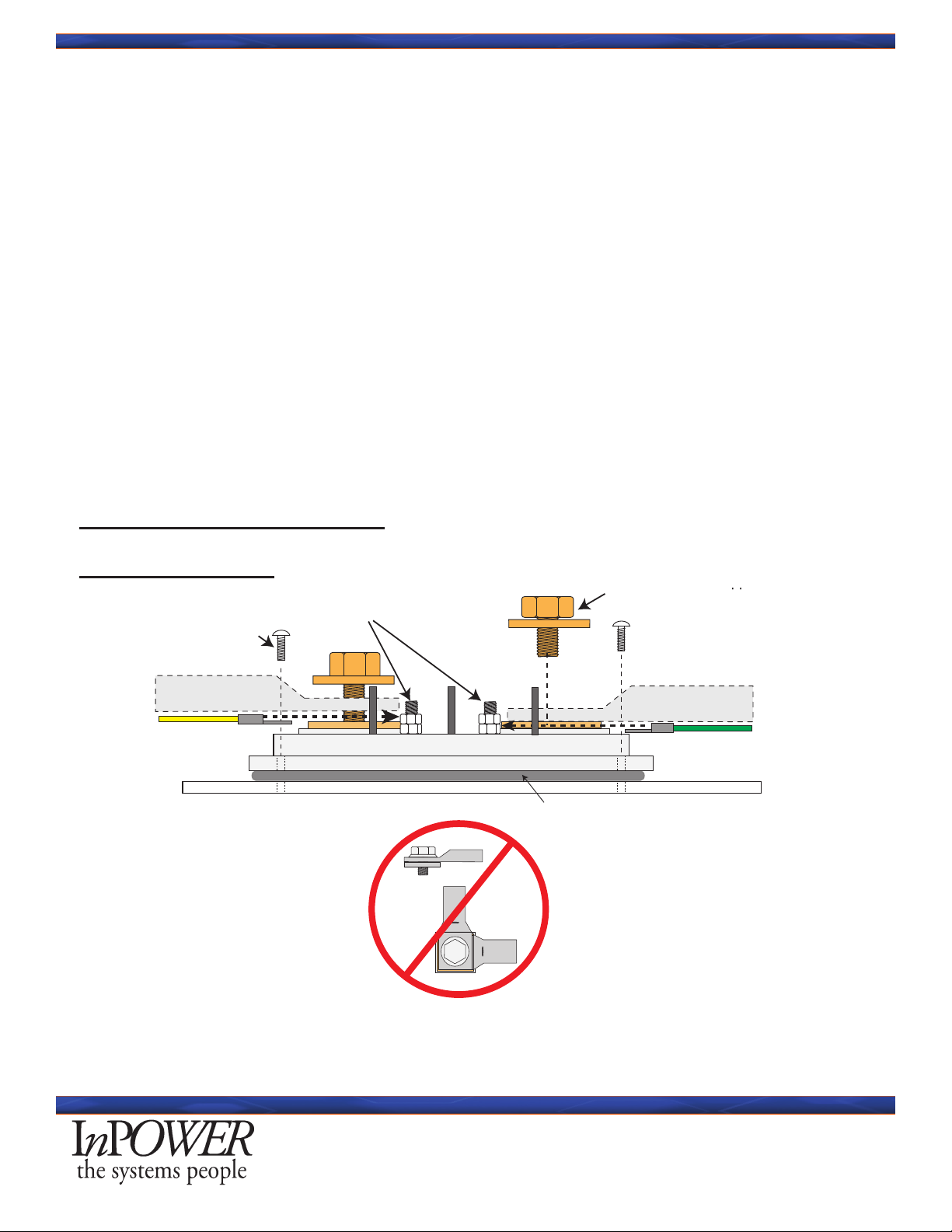
5.3 Mounting Diagram
No Stacking of Lugs!
If multiple terminations are needed, please refer
to the ABS3-200B or the ABS3-300
Double Crimp Lugs
(Customer Supplied)
Bronze Bolt and Copper Washer
Torque 10 to 15 Ft Lbs.
Ground Wire
To a good quality ground
(Optional User supplied) Small amount of Silicon Thermal Compound
METAL MOUNTING SURFACE
Optional Input
Control Wire (Boost)
Mounting Bolt
3/8 - 16 stainless steel threaded stud
Cable & Lug
Nut
Terminal boot (Not supplied with ABS2.)
Mounting screws (4 Required,
8-32 or 10-32) - (Not supplied
with ABS2.)
Thermal transfer pad
(supplied with ABS2)
IMPORTANT!
Torque mounting screws:
Minimum: 4 Inch Pounds
Maximum: 5 Inch Pounds
IMPORTANT!
Torque cable lug nuts to:
Minimum: 10 Foot pounds
Maximum: 15 Foot pounds
ABS2 Module
METAL MOUNTING SURFACE
NOTE - If the mounting screws cannot
provide a good quality ground you must
install a ground lug terminal and ground
wire.
IMPORTANT!
The mounting surface provides a means to remove heat that is generated by the ABS2
Auxiliary Battery Switch. If this surface is a poor conductor of heat, the unit will have a
lower currrent rating than if the surface is a good conductor of heat with a sufficiently
large area.
Boost Control and GND wire
and 8-32 Ring Terminal
Minimum: 4 Inch Pounds
Maximum: 5 Inch Pounds
Torque 8-32 mounting bolts
to 4-5 Inch Pounds
4-5 Inch Pounds

Page
8 of 8
ABS3 Owner’s Manual
Document: OM-215 Version Code: B
Date: Jan 28, 2021 Date: Aug 9, 2021
InPower LLC
8311 Green Meadows Drive
Lewis Center, Ohio 43035 USA
740-548-0965
www.InPowerLLC.com
© Copyright 2021 InPower LLC
5.4 Making the Final Connections
Do not drill out the contactor’s four mounting pad holes to use a larger bolt size. Drilling the
mounting holes out will void the warranty.
Grounding
Proper operation of the ABS3 is dependent on a good quality ground system with appropriate sized wires
for the load if the chassis is not a dependable source for a ground. Both the chassis battery and the auxil-
iary battery must be connected to a solid common ground. Be wary of attaching to the frame since many
manufacturers only recommend grounding directly to the Engine Block as a guaranteed ground. Con-
sult the recommended grounding documentation for your vehicle. The ABS3 must be connected to this
common ground. Install a #16 AWG ground wire with a ring terminal under one of the four ABS mounting
screws and connect it to the common battery ground. It is generally considered that the highest quality
ground is at the chassis battery’s negative terminal (although it is best to consult your chassis manufac-
turer’s documentation).
Connect the Power Cables and Boost Input Prepare the cables to the batteries using a suitable size cable
for the current required. Install a double crimped (or 360 degree crimped) lug terminal on the ends. Termi-
nal BAT1 is connected to the positive terminal of the chassis battery and terminal BAT2 is connected to the
positive terminal of the auxiliary battery.
For the Optional Boost Input Control, install a #16 AWG ground wire with a ring terminal and connect that
to a 12V control voltage. This can be a switch or voltage source of your choice. Refer to the Input voltage
specications for this interface.
Torque the 8/32 Screw Terminal with Brass Nuts to 4 to 5 Inch Lbs).
6.0 Testing Procedure
Make the following resistance measurements with a digital multimeter with all wires removed from the
ABS3-200.
1. Measure the resistance between the two power terminals (BAT 1 to BAT 2). The resistance
should be 210-220 KOhms.
2. Measure the resistance from the control INPUT terminal to the GND terminal. The resistance
should be 130 KOhms.
3. Measure the resistance of each power terminal to a GND terminal with the + probe on the power
terminal.
4. The resistance should be 105-110KOhms (BAT 1) and 105-110KOhms (BAT 2).
InPower LLC
8311 Green Meadows Drive
Lewis Center, Ohio 43035
740-548-0965
www.InPowerLLC.com
This manual suits for next models
2
Table of contents
Other InPOWER Switch manuals


