InPOWER SSC42-275 User manual
InPower LLC
8311 Green Meadows Drive
Lewis Center, Ohio 43035
740-548-0965
www.InPowerLLC.com
© Copyright 2023 InPower LLC
SSC42-275 Owners Manual
Page
1 of 6 Document: OM-85 Version Code: F
Date: October 30, 2008 Date: May 24, 2023
Electrical System Solutions
OWNERS MANUAL
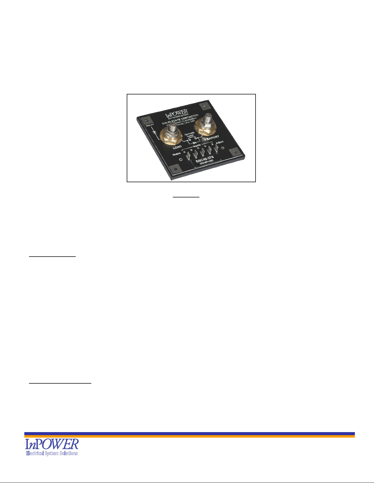
InPower Model SSC42-275
1. Introduction
The InPower Ambulance Module Power Disconnect Switch is intended for use in ambulances to disconnect battery
power from module loads, such as emergency lights, patient compartment lights, oodlights and loading lights. The
module contains a high current solid state contactor (power switch), a current sensor and a microprocessor control and
monitor circuit. Its over-current shutdown rating is 275 amps with a surge rating of 800 amps, and it provides automatic
fault shutdown for over current and loss of ground. The standard model described in this manual is SSC42-275, but
many custom programs are available. Please call us for more information.
Five control inputs offer a variety of different control congurations, including up to three time delayed power shut-off
modes. Input A allows instant shut-off, Inputs B, C and D offer time delayed shut-off modes, and Input E cancels all
timed shut-offs.
An amber LED indicator displays the power switch status. It illuminates any time the power switch is on, and it ashes
when switch is on and the timer is running in a timed shut-off mode. The LED blinks at a fast rate to indicate a fault shut
down condition.
The DC power terminations are two 3/8 – 16 threaded studs with brass contact pads. The ve control inputs are 0.25
inch male faston blade terminals. The four mounting holes provide the required connection to ground.
Load Considerations: Relays/Solenoids on the output must incorporate Fly Back Suppression Diodes/Circuitry.
These Relays/Solenoids (without suppression) can create large voltage and current spikes which damage electron-
ics. Having inductive loads without suppression violates your unit’s warranty and may damage your vehicles elec-
tronics!
Contents
1. Introduction........................................ ...............................................................1
2. System Diagram........................... ....................................................................2
3. System Operation .............................................................................................3
4. Installation Procedure .......................................................................................4
5. Specications ...................................................................................................6
6. Mechanical Drawings .......................................................................................6
Ambulance Module Power Disconnect Switch
with One On/Off and Three Time Delayed Shutoff Modes

InPower LLC
8311 Green Meadows Drive
Lewis Center, Ohio 43035
740-548-0965
www.InPowerLLC.com
© Copyright 2023 InPower LLC
SSC42-275 Owners Manual
Page
2 of 6 Document: OM-85 Version Code: F
Date: October 30, 2008 Date: May 24, 2023
Electrical System Solutions
2. System Diagram
Ground
Electronic Switch
LOAD
+BATTERY
Solid State Contactor
Lewis Center, Ohio
www.InPowerLLC.com
PATENT PENDING
Inputs
ABCDEAdjust
Status
Model SSC42-275
275 Amp Contactor
Fuse
Module 12 Volt Loads
Emergency Lights, Flood lights,
Loading Lights, Compartment
lights
Battery Starter Alt.
Off
On
Control Switch
(+12 Volt Control)
+12 Volts
Off
On
Control Switch
(+12 Volt Control)
+12 Volts
Off
On
Control Switch
(Ground)
Ground
Control Switch
(Ground Control)
Ground
A
Off
B
Ground
Timer Cancel Switch
(3-position, center off,
positions A and B momentary)
Operation:
Momentarily pressing control switch to
position A once will turn on module power
for a fixed 5 minute period. Pressing it twice
will do same but for 10 minutes, and three
times for 15 minutes. Pressing it a fourth
time will reset/cancel the sequence and turn
off the module power.
Momentarily pressing control switch to position
B will reset (cancel) any timer shut down mode
that is running.
Input B and Input C:
Operation - SSC42-275 & SSC42-275-SPC43:
Control switch to On turns on module power.
Control switch to Off starts adjustable timer.
When timer expires, module power turns off.
Operation - SSC42-275-SPC42:
Control switch to On turns on module power and
immediately starts adjustable timer. When timer
expires module power turns off. Control switch
must be turned of prior to next operation.
Operation:
Control switch to On turns on module power.
Control switch to Off turns off module power
with no time delay.
LED Indicator:
• On solid when module
power is on.
• Flashes when shut-down
timer is running.
• Flashes at a fast rate to
indicate a fault shut down.
Timer Adjustment:
SSC42-275 0 to 20 minutes
SSC42-275-SPC42 0 to 20 minutes
SSC42-275-SPC43 0 to 10 seconds
Operation:
Operating reset switch will cancel (reset to
zero) any shut down timer that is running.
(Momentary)
Input A - No
Timed Off Mode
Input B - Adjustable
Timed Off Mode
Input C - Adjustable
Timed Off Mode
Input D - Preset Timed
Off Mode
Input E - Timer Cancel
Input E - Timer Cancel

InPower LLC
8311 Green Meadows Drive
Lewis Center, Ohio 43035
740-548-0965
www.InPowerLLC.com
© Copyright 2023 InPower LLC
SSC42-275 Owners Manual
Page
3 of 6 Document: OM-85 Version Code: F
Date: October 30, 2008 Date: May 24, 2023
Electrical System Solutions
3. System Operation
3.1 Electronic Power Switch
The SSC42-275 module power disconnect switch is 100% electronic. When activated, it connects the LOAD
terminal to the +BATTERY terminal, delivering power to the module’s 12 Vdc loads. The highly efcient power
switch has a very low on-resistance, resulting in a very low voltage drop and low internal heat dissipation. As
many DC loads are inductive, the power switch contains an internal clamping diode between its LOAD terminal
and ground. This suppresses negative inductive voltage spikes when the power is switched off. Note that it is
very important that the unit is properly grounded to allow this clamping diode to work effectively.
The power switch monitors the amount of current passing through it, and if this current exceeds specications,
the power switch turns off and stays latched until reset. The current trip point activates if the 275 amp limit is
exceeded for 750 milliseconds. To recover from the latched shutdown condition, the overload condition must be
cleared. Then, either remove battery power from +BATTERY terminal or cycle Input A, B or C to On then Off.
3.2 Control Inputs
The module has ve inputs that perform various functions.
Input A: Activates with +12 volts. Activating this input turns the power switch on. Removing the input turns the
power switch off with no time delay.
Input B: Activates with +12 volts. Activating this input turns the power switch on. Removing this input, a timer
starts. When the timer expires, the power switch shuts off. The timer is adjustable by a single turn potentiometer
located on top of the module. This timer ranges from 0 to 20 minutes on the standard model.
Input C: Activates with ground. Function is otherwise identical to Input B.
Input D: Activated by momentary ground. When activated, the power switch turns on for a xed period of time in
multiples of ve minutes. The interval is determined by how many input pulses are received (one, two or three).
If one pulse is received, the power switch turns on for ve minutes. If two, ten minutes. If three, fteen minutes.
When the period is up or if a fourth pulse is received, the switch turns off.
Input E: Activates by momentary ground. When activated, any timer running is immediately cancelled and reset,
and the power switch turns off.
LED Status Indicator: the amber LED indicator is located on top of the module. Steady on indicates the power
switch is on with no timer running. The LED ashes slowly when a timer is running. It blinks rapidly when a fault
has occurred.
Fault Shutdowns: the following conditions will cause the power switch to shut off and stay latched in the shut off
state until it is reset:
1. over current
2. loss of ground
Resetting Fault Shutdowns: To reset after a fault shutdown, rst remove the source of the fault. Then, do one of
the following:
Disconnect and reconnect the battery cable from the +BATTERY terminal
Or cycle Input A, B or C to on then off.

InPower LLC
8311 Green Meadows Drive
Lewis Center, Ohio 43035
740-548-0965
www.InPowerLLC.com
© Copyright 2023 InPower LLC
SSC42-275 Owners Manual
Page
4 of 6 Document: OM-85 Version Code: F
Date: October 30, 2008 Date: May 24, 2023
Electrical System Solutions
4. Installation Procedures
This section provides instructions for installing the InPower Model SSC42-275 Ambulance Module Power
Disconnect Switch. It is important that you follow these instructions carefully and contact InPower if you need
assistance or more information.
4.1 Safety Precautions
This power switch product has been designed and manufactured to meet the intended application requirements
and specications. Any modications to the product or to the installation procedure can be dangerous and will
void InPower’s warranty.
• Read and understand the instructions in this manual and other manuals before starting the installation.
• Make sure that the vehicle battery power is disconnected during installation of the Interlock and lift systems.
• Reconnect the battery when the system installation is complete.
• Locate a dry location free of water or chemical spraying as this may damage the Contactor.
• Wear appropriate safety equipment, such as protective eyeglasses, face shield and clothing when installing
equipment and handling the battery.
• Be careful when working near a battery. Make sure that the area is well ventilated and that there are no
ames near the battery. Never lay objects on the battery that can short the terminals together. If battery
acid gets in your eyes, immediately seek rst aid. If acid gets on your skin, immediately wash it off with
soap and water.
4.2 Mounting
Determine where the disconnect switch will be mounted. Take into consideration the large power cables that
must connect the switch to the battery positive, as well as the power cables from the disconnect switch to the
12 volt loads. Note that a fuse is necessary at the battery end of the cable running between the battery and the
battery terminal on the disconnect switch.
The module must be mounted on a at metal surface to absorb the heat produced by the switch. We
recommend an aluminum plate 1/8” x 16” x 16” or larger. If this size and type of mounting surface is unavailable,
it is necessary to derate the maximum current rating of the power switch. To facilitate heat transfer, a square
piece of thermal transfer material is supplied on the mounting surface of each disconnect switch. Remove the
clear plastic protective backing before mounting.
Secure the disconnect switch to the mounting surface using four screws. If the mounting surface is a good
quality ground, the mounting screws will provide a good ground connection. However, if the mounting surface
is not a good ground or you are unsure, you must install a ground wire with a ring terminal under one of the
mounting screws. This ground wire must be a low resistance to battery negative.
The disconnect switch should not be located in the engine compartment or any location near the engine’s heat.
Although the module is sealed, we do not recommend installing it in a location that is exposed to the outside
environment where the unit may be exposed to water or chemical spray.
WARNING
!
InPower LLC
8311 Green Meadows Drive
Lewis Center, Ohio 43035
740-548-0965
www.InPowerLLC.com
© Copyright 2023 InPower LLC
SSC42-275 Owners Manual
Page
5 of 6 Document: OM-85 Version Code: F
Date: October 30, 2008 Date: May 24, 2023
Electrical System Solutions
4.3 Connecting the power cables
First, make sure the battery is disconnected!
Use a suitable size cable for the current required and install a crimped terminal lug on the end. Be sure you
have installed a protection device, such as a fuse, fuse link or circuit breaker, at the battery end of the cable.
Torque the nut to between 10 and 15 Ft pounds. Prepare the cable for the loads and install this as you did with
the battery cable.
Stacking multiple cable terminal lugs on the studs is not recommended.
4.4 Control Circuit
The control circuit wiring consists of one or more remote switches wired to the ve disconnect switch control
inputs labeled Input A through Input E.
Inputs A and B must be activated by a positive DC voltage greater than 2.6 V. We recommended that the remote
switches be connected to a +12 V source.
Inputs C, D and E must be activated by a ground signal, so their remote switches must be wired to a good
ground – i.e. low resistance to battery negative.
To attach the control wires, use female 0.25 inch faston blade terminals. Be sure to install a strain relief on the
control wires near the disconnect switch.
Please refer to the diagram on page 2 for further detail.
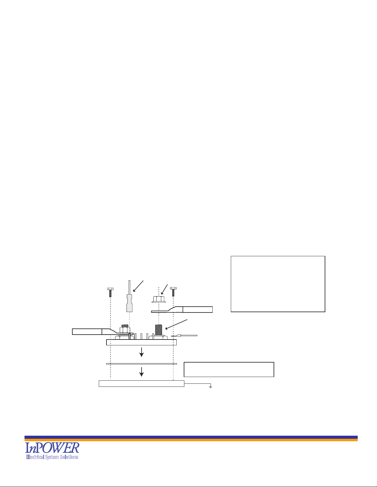
4.5 Installation Diagram
Mounting & Grounding Screws
4 required
6-32 or 8-32
3/8-16 bronze threaded stud
Locking nut
(provided with unit)
Cable & Lug
Cable & Lug
Ground Wire & Lug Terminal
Male Faston
terminals
Control Wire
and 1/4 inch
female Faston
terminal (typical)
SSC42-275 Module
Thermal Transfer Pad
Mounting Surface
Ground
Aluminum Plate 1/8" x 16" x 16" or larger
Torque Nuts to:
Min: 10 Ft. Pounds
Max: 15 Ft. Pounds
Note: If the mounting screws cannot
provide a good quality ground, you
must install a ground lug terminal
and ground wire
To 12 Volt
Module Loads
Note: The Mounting Surface provides a means to remove heat generated by the SSC42-275. If this surface is a
poor conductor of heat, the disconnect switch will have a lower current rating than if the surface is a good
conductor
CABLE & LUG WARNING:
Do not add washers. Adding washers
will increase the terminal resistance
and may result in overheating.
Do not stack cable lugs. The studs
are not intended to hold more than
one cable lug.
SSC-42-275 to be mounted in a dry area,
free of water or chemical spray.

InPower LLC
8311 Green Meadows Drive
Lewis Center, Ohio 43035
740-548-0965
www.InPowerLLC.com
© Copyright 2023 InPower LLC
SSC42-275 Owners Manual
Page
6 of 6 Document: OM-85 Version Code: F
Date: October 30, 2008 Date: May 24, 2023
Electrical System Solutions
5. Specications
Under Voltage Rating: +7.5Vdc
Current Rating:
Current Trip Rating: 275 amps for 750 milliseconds
Surge Current Rating: 800 amps
On-resistance at maximum current: 660 microohms
Turn-On Delay: 10 milliseconds
Turn-Off Delay: 10 milliseconds plus off-delay timer
Control Input:
Connector Type: 0.25 inch male faston blade terminal x 5
Control Voltage
Input A: >2.6 Vdc to activate
Input B: >2.6 Vdc to activate
Input C: ground to activate
Input D: ground to activate
Input E: ground to activate
Weight: 0.30 lbs (0.136 kg)
Dimensions: 4.15 x 4.15 x 1.50 inches
Power Terminals: Two 3/8 - 16 bronze threaded studs with zinc plated locking
nuts
Mounting Surface: For optimal performance, a at metal mounting surface, such
as a 1/8 x 16 x 16 inch aluminum plate
In a dry environment free of water or chemical spray
6. Mechanical Drawing
+BAT
Ground
Electronic Switch
LOAD
+BATTERY
4.15
1.50
4.15
Terminal lug to ensure
a good quality ground
(any mounting hole).
Stainless steel locking nut
(furnished with product)
3/8 - 16 stainless steel
threaded stud
Solid State Contactor
Lewis Center, Ohio
www.InPowerLLC.com
PATENT PENDING
Inputs
ABCDEAdjust
Status
Model SSC42-275
275 Amp Contactor
0.36
Brass contact pad
Metal mounting surface such as a
1/8 x 16 x 16 inch aluminum plate.
Thermal transfer pad
furnished with product.
SSC-42-275 to be mounted in a dry area,
free of water or chemical spray.
Table of contents
Other InPOWER Switch manuals

Popular Switch manuals by other brands

Creator
Creator MAX1301 user manual

SMC Networks
SMC Networks SMC6248M Technical specifications

Avaya
Avaya Cajun P333T user guide

pro bel
pro bel Freeway Series user guide

SICK
SICK i16S operating instructions

United Electric Controls
United Electric Controls Spectra 12 Series Installation and maintenance instructions


