manuals.online logo
Brands
  1. Home
  2. •
  3. Brands
  4. •
  5. United Electric Controls
  6. •
  7. Switch
  8. •
  9. United Electric Controls Spectra 12 Series User manual

United Electric Controls Spectra 12 Series User manual

GENERAL
MISUSE OF THIS PRODUCT MAY CAUSE EXPLOSION AND PERSONAL INJURY.
THESE INSTRUCTIONS MUST BE THOROUGHLY READ AND UNDERSTOOD
BEFORE UNIT IS INSTALLED.
THIS EQUIPMENT IS SUITABLE FOR USE IN CLASS I, DIVISIONS 1 & 2,
GROUPS A, B, C AND D; CLASS II, DIVISIONS 1 & 2, GROUPS E, F AND G;
CLASS III; OR NON-HAZARDOUS LOCATIONS ONLY. -50 °C (-58 °F) ≤ Tamb.
≤ 95 °C (203 °F), ENCLOSURE TYPE 4X.
THIS EQUIPMENT IS ATEX CERTIFIED (OPTION M419) FOR EQUIPMENT CAT-
EGORY 2. SUITABLE FOR APPROPRIATE USE IN GAS ZONE 1 AND DUST ZONE
21 APPLICATIONS.
0539 DEMKO 03 ATEX 0252466X
II 2 G EEx d IIC T6
II 2 D T+85 °C
-50 °C ≤ Tamb. ≤+80 ºC, IP66
BEFORE INSTALLING, CHECK THE SENSOR MODEL SELECTED FOR
COMPATIBILITY TO THE PROCESS MEDIA IN CONTACT WITH THE SENSOR AND
WETTED PARTS.
PROOF PRESSURE* LIMITS STATED IN THE LITERATURE AND ON NAME-
PLATES MUST NEVER BE EXCEEDED, EVEN BY SURGES IN THE SYSTEM.
OCCASIONAL OPERATION OF UNIT UP TO PROOF PRESSURE IS ACCEPTABLE
(E.G., START-UP, TESTING). CONTINUOUS OPERATION SHOULD NOT EXCEED
THE DESIGNATED OVER RANGE PRESSURE.
*Proof Pressure
The maximum pressure to which a pressure sensor may be occasionally subjected,
which causes no permanent damage (e.g., start-up testing). (May require set-point
adjustment).
THESE PRODUCTS DO NOT HAVE ANY FIELD REPLACEABLE PARTS. ANY
SUBSTITUTION OF COMPONENTS MAY IMPAIR SUITABILITY FOR CLASS I,
DIVISION 1.
The Spectra-12 switch utilizes a diaphragm or a piston sensor to detect a pressure
change. The response, at a predetermined set point, actuates or deactuates a SPDT
or DPDT snap-acting switch, converting a pressure signal into an electrical signal.
Control set point may be varied by turning the internal slotted adjustment screw
according to procedures outlined in Part II-Adjustments.
Tools Needed
1-1/6" Open end wrench
MOUNTING
ALWAYS LOCATE UNITS WHERE SHOCK, VIBRATION AND AMBIENT TEMPERATURE
FLUCTUATIONS ARE MINIMAL. DO NOT MOUNT IN AMBIENT TEMPERATURE
AREAS EXCEEDING 203°F (IF UL/cUL APPROVAL IS APPLICABLE) OR 80 °F (IF
ATEX APPROVAL IS APPLICABLE). IF SEVERE PRESSURE SURGES ARE EXPECTED,
CONSIDER THE USE OF A PRESSURE SNUBBER.
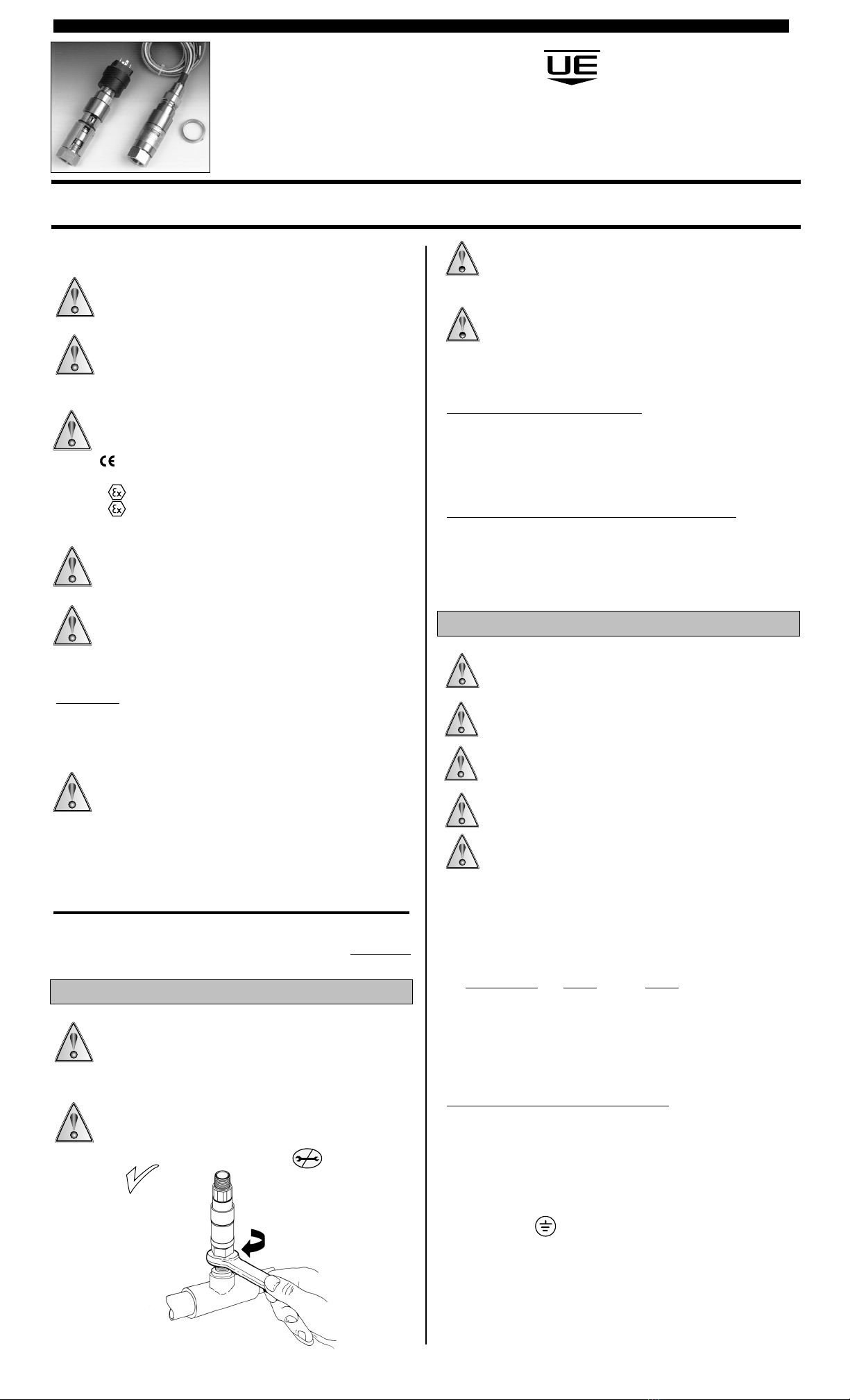
FOR PRESSURE MODELS, MOUNT USING PRESSURE CONNECTION: ALWAYS USE A
WRENCH ON PRESSURE CONNECTION WRENCH FLAT. (SEE FIGURE 1)
FOR DIFFERENTIAL PRESSURE MODELS, MOUNT UNIT AGAINST A RIGID
SUPPORT USING THE MOUNTING BRACKET ATTACHED TO THE SENSOR
ASSEMBLY. THEN CONNECT THE HIGH AND LOW PRESSURE CONNECTIONS
(HIGH PRESSURE PORT IS ON THE LEFT, WHEN FACING THE UNIT).
UNIT MAY BE MOUNTED IN ANY POSITION. HOWEVER, IF INSTAL-
LATION LOCATION RESULTS IN FREQUENT EXPOSURE TO
LIQUID IT IS RECOMMENDED THAT THE UNIT BE MOUNTED VERTICALLY WITH
THE PRESSURE CONNECTION DOWN. IF UNIT IS TO BE SET AFTER MOUNTING, VERIFY
THAT ADJUSTMENT OPENING IS ACCESSIBLE. “FRONT” MARKING ON NAMEPLATE MUST
FACE THE OPERATOR.
1/2” NPTM or M20 Electrical Connection
When panel mounting, mount through 7/8” clearance hole in panel. Hold
in place with serrated 1/2” or M20 conduit nut. Always support the unit by
holding a wrench on the hex.
TO ATTACH CONDUIT CONNECTION, HOLD ELECTRICAL CONNECTION STEADY WITH WRENCH ON
HEX, THEN THREAD ON CONDUIT.
Surface Mounting Bracket Kit (P/N 62169-13), Option M449
Open the adjustment cover and orient the unit so that adjustment opening will be acces-
sible when the switch is mounted. Close the adjustment cover ensuring that the bracket
does not interfere with the cover. Failure to do so may result in improper sealing of
adjustment cover. Mount assembly in desired location, following instructions included with
mounting bracket kit.
WIRING
DISCONNECT ALL SUPPLY CIRCUITS BEFORE WIRING UNIT. ELECTRICAL RAT-
INGS STATED IN LITERATURE AND ON NAMEPLATE MUST NOT BE EXCEED-
ED. OVERLOAD ON A SWITCH CAN CAUSE FAILURE ON THE FIRST CYCLE.
EXTERNAL GROUNDING SCREW (OPTION M460) IS REQUIRED FOR NON-
METALLIC CONDUIT SYSTEMS.
WIRE IN ACCORDANCE WITH LOCAL AND NATIONAL ELECTRICAL CODES. BY
THE INSTALLATION, THE WIRES SHALL BE PROTECTED AGAINST MECHANI-
CAL DAMAGE. E.G. BY USE OF A CONDUIT.
DIN CONNECTOR (OPTION M515) IS NOT APPROVED FOR CLASS I, DIV.
1/HAZARDOUS LOCATIONS/FLAMEPROOF ATMOSPHERES.
THE WIRING TO THE PRESSURE SWITCH MUST ONLY BE CONNECTED IN THE
SAFE AREA OR BY AN APPROVED TERMINAL BOX CERTIFIED TO EN 50 018
OR EN 50 019 FOR HAZARDOUS LOCATIONS/FLAMEPROOF ATMOSPHERES.
1/2" NPTM or M20 conduit connection is provided on top of the unit with 72” lead-
wires. Unit is available with SPDT or DPDT operation. External grounding screw and
clamp is provided with option M460.
Factory Sealed Leadwires are color coded:
TERMINALS
SPDT DPDT
SWT1 SWT2
Common Brown Brown Yellow
Normally Closed Red Red Black
Normally Open Blue Blue Violet
Ground Green Green
DIN Connector with 4 Male Terminals (figure 3)
Wire in accordance with local and national electrical codes. Connector conforms to
DIN 43650. Use a mating DIN connector (female type). Coding:
TERMINALS
Terminal #1 Common
Terminal #2 Normally Closed
Terminal #3 Normally Open
Ground
IM12-03
Spectra 12 Series
Explosion Proof, Pressure and
Differential Pressure Switches
Part I - Installation
figure 1
DO NOT TURN
SWITCH HOUSING
MOUNT VIA
PRESSURE
CONNECTION
Please read all instructional literature carefully and thoroughly before starting. Refer to the final page for the listing of
Recommended Practices, Liabilities and Warranties.
UNITED ELECTRIC
CONTROLS
Installation and Maintenance
Instructions
figure 1
RECOMMENDED PRACTICES AND WARNINGS
United Electric Controls Company recommends careful consideration
of the following factors when specifying and installing UE pressure
and temperature units. Before installing a unit, the Installation and
Maintenance instructions provided with unit must be read and under-
stood.
• To avoid damaging unit, proof pressure and maximum temperature
limits stated in literature and on nameplates must never be exceeded,
even by surges in the system. Operation of the unit up to maximum
pressure or temperature is acceptable on a limited basis (e.g., start-up,
testing) but continuous operation must be restricted to the designated
adjustable range. Excessive cycling at maximum pressure or tempera-
ture limits could reduce sensor life.
• A back-up unit is necessary for applications where damage to a pri-
mary unit could endanger life, limb or property. A high or low limit
switch is necessary for applications where a dangerous runaway
condition could result.
• The adjustable range must be selected so that incorrect, inadvertent
or malicious setting at any range point cannot result in an unsafe
system condition.
• Install unit where shock, vibration and ambient temperature fluc-
tuations will not damage unit or affect operation. Orient unit so that
moisture does not enter the enclosure via the electrical connection.
When appropriate, this entry point should be sealed to prevent mois-
ture entry.
• Unit must not be altered or modified after shipment. Consult UE if
modification is necessary.
• Monitor operation to observe warning signs of possible damage to
unit, such as drift in set point or faulty display. Check unit immedi-
ately.
• Preventative maintenance and periodic testing is necessary for criti-
cal applications where damage could endanger property or person-
nel.
• For all applications, a factory set unit should be tested before use.
• Electrical ratings stated in literature and on nameplate must not be
exceeded. Overload on a switch can cause damage, even on the first
cycle. Wire unit according to local and national electrical codes,
using wire size recommended in installation sheet.
• Do not mount unit in ambient temp. exceeding published limits.
LIMITED WARRANTY
Seller warrants that the product hereby purchased is, upon delivery,
free from defects in material and workmanship and that any such
product which is found to be defective in such workmanship or mate-
rial will be repaired or replaced by Seller (Ex-works, Factory, Watertown,
Massachusetts. INCOTERMS); provided, however, that this warranty applies
only to equipment found to be so defective within a period of 36 months
from the date of manufacture by the Seller. Seller shall not be obligated
under this warranty for alleged defects which examination discloses are
due to tampering, misuse, neglect, improper storage, and in any case
where products are disassembled by anyone other than authorized Seller’s
representatives. EXCEPT FOR THE LIMITED WARRANTY OF REPAIR AND
REPLACEMENT STATED ABOVE, SELLER DISCLAIMS ALL WARRANTIES
WHATSOEVER WITH RESPECT TO THE PRODUCT, INCLUDING ALL
IMPLIED WARRANTIES OF MERCHANTABILITY OR FITNESS FOR ANY
PARTICULAR PURPOSE.
LIMITATION OF SELLER’S LIABILITY
Seller’s liability to Buyer for any loss or claim, including liability incurred
in connection with (i) breach of any warranty whatsoever, expressed or
implied, (ii) a breach of contract, (iii) a negligent act or acts (or negligent
failure to act) committed by Seller, or (iv) an act for which strict liability
will be inputted to seller, is limited to the “limited warranty” of repair
and/or replacement as so stated in our warranty of product. In no event
shall the Seller be liable for any special, indirect, consequential or other
damages of a like general nature, including, without limitation, loss of
profits or production, or loss or expenses of any nature incurred by the
buyer or any third party.
UE specifications subject to change without notice.
EMCO5M503
Part II - Adjustments
figure 2
IM12-03
Tools Needed
Flathead screwdriver with 3/16” or 1/4” wide blade
1. Connect control to pressure source.
2. With power disconnected, slide cover toward electrical terminations while twisting
it to over-come friction.
3. Connect power to terminals or leads.
4. Insert screwdriver into adjustment slot and turn left (clockwise) to increase
setting or right (counterclock-wise) to decrease setting.(See figure 2).
For setting on RISE, apply desired pressure and turn adjustment left (clockwise) until
switch clicks (circuit across N.O. and COM terminals closes).
For setting on FALL, apply pressure equal to normal system operating pressure.
Reduce source pressure to setpoint value. Turn adjustment right (counter clockwise)
until switch clicks (circuit across N.C. and COM terminals closes).
Dimensions
Pressure
Type 2, 3, 5 Sensor Type 4, 6, 8, P1-P3 Sensor Type 7, 9 Sensor
Dimension A
Types Inches mm NPT
2 47∕8" 123.9 1/2"
3 47∕8" 123.9 1/2"
4 47∕8" 123.9 1/4"
5 47∕8" 123.9 1/2"
6 47∕8" 123.9 1/4"
7 513∕32" 137.5 1/2"
8 47∕8" 123.9 1/4"
9 513∕32" 137.5 1/2"
K1-K3 611∕16" 169.9 1/8"
K4-K6 615∕16" 176.2 1/8"
P1-P3 53/8" 136.5 1/4"
Standard Configuration
Type K4-K6Type K1-K3
Differential Pressure
Types K1-K3 and K4-K6 shown with mounting bracket attached
Option M515 DIN Connection
figure 3
UNITED ELECTRIC
CONTROLS
180 Dexter Avenue, P.O. Box 9143
Watertown, MA 02471-9143 USA
Telephone: 617 926-1000 Fax: 617 926-2568
http://www.ueonline.com

Other United Electric Controls Switch manuals

United Electric Controls J21K User manual

United Electric Controls

United Electric Controls J21K User manual

United Electric Controls ONE Series User manual

United Electric Controls

United Electric Controls ONE Series User manual

United Electric Controls 54 Series Owner's manual

United Electric Controls

United Electric Controls 54 Series Owner's manual

United Electric Controls 12 Series Owner's manual

United Electric Controls

United Electric Controls 12 Series Owner's manual

United Electric Controls J120 User manual

United Electric Controls

United Electric Controls J120 User manual

United Electric Controls ONE Series User manual

United Electric Controls

United Electric Controls ONE Series User manual

United Electric Controls 54 Series Owner's manual

United Electric Controls

United Electric Controls 54 Series Owner's manual

United Electric Controls 105 Series User manual

United Electric Controls

United Electric Controls 105 Series User manual

United Electric Controls 100 Series User manual

United Electric Controls

United Electric Controls 100 Series User manual

United Electric Controls 12 Series User manual

United Electric Controls

United Electric Controls 12 Series User manual

United Electric Controls 54 Series User manual

United Electric Controls

United Electric Controls 54 Series User manual

United Electric Controls H119 User manual

United Electric Controls

United Electric Controls H119 User manual

United Electric Controls J21K User manual

United Electric Controls

United Electric Controls J21K User manual

United Electric Controls 117 Series Owner's manual

United Electric Controls

United Electric Controls 117 Series Owner's manual

United Electric Controls Excela 1GSWLL User manual

United Electric Controls

United Electric Controls Excela 1GSWLL User manual

United Electric Controls B117 User manual

United Electric Controls

United Electric Controls B117 User manual

United Electric Controls 117 Series User manual

United Electric Controls

United Electric Controls 117 Series User manual

United Electric Controls 100 Series User manual

United Electric Controls

United Electric Controls 100 Series User manual

United Electric Controls 360 Series User manual

United Electric Controls

United Electric Controls 360 Series User manual

Popular Switch manuals by other brands

TRENDnet TPE-S80 Quick installation guide

TRENDnet

TRENDnet TPE-S80 Quick installation guide

NLS CAT5-A2 user guide

NLS

NLS CAT5-A2 user guide

Vivo Link VL120000 user manual

Vivo Link

Vivo Link VL120000 user manual

CSL 301107 user manual

CSL

CSL 301107 user manual

Sensor Switch WSXA JOT installation instructions

Sensor Switch

Sensor Switch WSXA JOT installation instructions

Black Box KVT1IP1UV user guide

Black Box

Black Box KVT1IP1UV user guide

Xantech RS41AV installation instructions

Xantech

Xantech RS41AV installation instructions

NETGEAR ProSafe Plus JFS524E installation guide

NETGEAR

NETGEAR ProSafe Plus JFS524E installation guide

ReadyLinks GL Series user guide

ReadyLinks

ReadyLinks GL Series user guide

Rocket Fish RF-G1185 Guide d'installation rapide

Rocket Fish

Rocket Fish RF-G1185 Guide d'installation rapide

Azbil C6097A user manual

Azbil

Azbil C6097A user manual

Allied Telesis AT-9900 Series release note

Allied Telesis

Allied Telesis AT-9900 Series release note

Redback A 4931 operating manual

Redback

Redback A 4931 operating manual

Garland EdgeSafe M10GMSBPv2 user guide

Garland

Garland EdgeSafe M10GMSBPv2 user guide

Acnodes KP802 user manual

Acnodes

Acnodes KP802 user manual

H3C S9820-8C-SAN installation guide

H3C

H3C S9820-8C-SAN installation guide

Extron electronics SVS 100 user manual

Extron electronics

Extron electronics SVS 100 user manual

Transition Networks PSV-2/14-45 user guide

Transition Networks

Transition Networks PSV-2/14-45 user guide

manuals.online logo
manuals.online logoBrands
  • About & Mission
  • Contact us
  • Privacy Policy
  • Terms and Conditions

Copyright 2025 Manuals.Online. All Rights Reserved.