INRAD FT-920 User manual
© 2008 International Radio Corporation. Modifications are done at your own risk; seek assistance if you
are not qualified to make these modifications. International Radio assumes no responsibility for any
damages or injuries resulting from improper installation of this modification kit.
Revised 2008-10-15
FT-920: Installing the Inrad Roofing Filter Mod
The FT-920 roofing filter mod consists of a 6 pole, 4 to 5 kHz wide filter
followed by a high dynamic range feedback amplifier. The amplifier provides
enough gain to overcome the filter insertion loss.
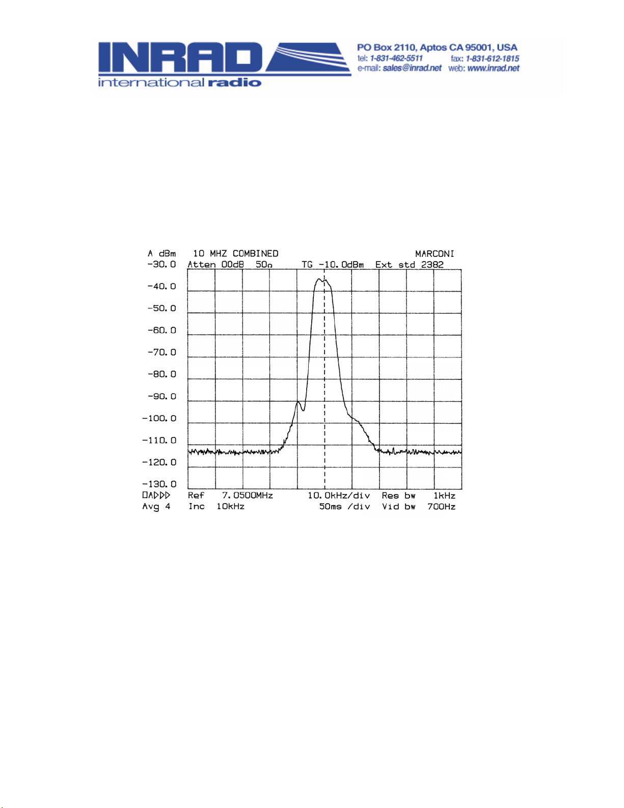
The plot below shows the sweep frequency response of the front end with the
Inrad roofing filter mod in place. For comparison, the OEM filter is about 20
kHz wide at the -6 dB points.
The result of the bandwidth improvement is the reduction of close in
intermodulation from multiple signals. The IMD dynamic range will be
improved up to 20 dB for signal spacings from 2 to 20 kHz. Also, the blocking
dynamic range will be improved for close in signals.

Frequently Asked Questions
1. What can you expect from this mod?
Less IMD in crowded band conditions, particularly from stations at offset
frequencies of 2 to 20 kHz on either side of the operating frequency.
2. Will it defeat the noise blanker?
There will be some change in the NB performance due to the narrower
bandwidth of the mod. In practice, it may not be noticeable.
3. Will this mod allow for wide band SSB, AM and FM reception?
The overall widest bandwidth will be determined by the roofing filter, which is
about 5 kHz. AM and FM will be degraded, but not excessively. Normal 2400
Hz SSB will not be affected.
Description of Operation
The roofing filter mod inserts a narrow band crystal filter after the first mixer
and before the OEM roofing filter. An amplifier is included to compensate for
the filter loss. Reducing the bandwidth at this point in the radio helps to keep
strong off-frequency signals out of the second mixer, where they can cause
intermodulation. Transmission is not changed, as it does not pass through
the roofing filter.
Installation Instructions
Warning: Modern radios contain components which may be damaged by
static discharge. Precautions must be taken to eliminate any static
electricity buildup between the operator and the radio before any of the
internal circuits are touched. If you are not familiar with the proper
techniques for this, consult the Radio Amateurs Handbook.
Warning: This modification requires a high level of soldering skill, possibly
beyond that normally possessed by the average radio amateur.
Professional assistance is advised if you are not confident that you have
this ability.
Note: If you have a known test signal available before you start, note the
S meter reading for the main and sub receivers. After the installation, the
S meter should read about the same as before.
© 2008 International Radio Corporation - 2 -

Preparing the Inrad Mod for Installation
1. Prepare one side of each coax cable by stripping ½ inch of outer
covering and shield from the end. Strip approximately 1/8 inch of
insulation from the center conductor.
2. Next, prepare the opposite side of each coax cable to accept a TMP
connector by stripping ½ inch of outer covering and shield. Strip
approximately 1/4 inch of insulation from the center conductor. Insert
the center conductor into the TMP connector center pin and solder it
in. Then take the dressed braid and solder it to the connector outer
shield. The cables should now be ready for the installation. See Figure
1 for more information on the cable preparation.
3. Set prepared cables aside.
Preparing the Radio for Installation
If you haven't already read the instructions completely, please do so now
before continuing.
1. Remove the DC power cord from the transceiver.
2. Place the radio upside down on a soft surface such as a towel, with the
front panel facing you.
3. Loosen the four screws on the sides of the upper case, but do not
remove them.
4. Remove the six screws holding the bottom cover in place. Remove the
bottom cover.
5. Turn the radio over and remove 9 screws in the top cover. Remove the
top cover.
6. Turn the radio over again so the bottom of the radio is facing up.
Locate T1013 and T1014 on the right front side of the main pc board.
The modifications will take place on the underside of the pc board in
this area.
7. On the large shielded assembly on the front left side, remove three
screws: two on the edge of the casting and one inserted through the
PC board.
8. Gently lift the assembly to unplug it from its connector. Peel back
enough of the two red tapes in the assembly underside to free the
wires. Unplug the connector from the assembly and leave the wires
© 2008 International Radio Corporation - 3 -

going to the main board. Use care as the wires are fragile. Set the
assembly aside on a soft surface next to the casting.
9. Remove the twelve screws holding the main board to the casting.
Detach the four white strip wire harnesses from the main board. Note
the location and orientation of each strip.
10. Raise the front edge of the PC board and move the cable in the right
front corner to the right. Slide the board toward the front panel and lift
the front edge up and over the casting until the connectors on the rear
edge are clear of the casting holes. Place a towel on the front panel
upper edge to protect it. When the board is free, raise it to the vertical
position and rotate it 90 degrees counterclockwise.
11. Lay the board and assembly on the towel on top of the radio casting.
12. Locate the work area between T1013 and T1014 on the trace side of
the board. Compare it to Figure 2. Note that each transformer has 5
terminals, a group of 3 and a group of 2. T1013 and T1014 have the 2
terminal groups facing each other with C1111 making a connection
between them. Remove C1111. Use a soldering iron tip which is wide
enough to unsolder both sides of the capacitor together. A toothpick
can be used to slide the capacitor off of its pads.
13. Examine Figure 3. Dress the coax cables up and to the center of the pc
board. Connect the coax cable center conductors to the pads left open
by C1111. The pad connecting to T1013 will go to J1 on the Inrad
mod. The pad connecting to T1014 will go to J2 on the Inrad mod.
Ground the shields to the nearest ground pad.
14. Check that the soldering is secure before turning the board over.
15. Reverse the removal procedure to reinstall the PC board and shielded
assembly. Use care to align the assembly pins with their sockets
before applying any pressure.
16. Set the radio on its left side with the panel facing left. The Roofing
Filter mod board will mount on the right side of the casting which is
now facing up.
17. Prepare the mod board by soldering the red wire to the +12V pad.
Ground will return through the coax shields.
18. Press the standoffs into the mod board holes from the bottom side.
19. Remove the safety papers from the sticky ends of the standoffs and
press the mod board assembly onto the top of the radio casting as
shown in Figure 4.
© 2008 International Radio Corporation - 4 -

20. Connect the red wire to the right end of R1305. It is a small power
resistor near the center rear of the radio. See Figure 5. Note: If the
Inrad Switchboard Mod is installed, the red wire can go directly to the
red +12V terminal on that unit.
21. Plug the two coax cables into J1 and J2 on the mod board. Note the
proper connections as pointed out in Step 13.
22. Turn the radio upside down. Dress the coaxes and red wire through
the opening in the casting near the front panel on the right side of the
radio as it lies up side down and through the opening in the front
center.
23. Fasten the new wires in place with tie wraps.
24. Turn the radio over. Replace the top cover. It is best to leave the top
cover screws loose. Note: Use extreme care to avoid damage to the
mod board.
25. Turn the radio upside down. Attach the bottom cover with the 5 black
screws. Use care to route the new wires so they are not pinched by the
cover.
26. Finish tightening all screws.
© 2008 International Radio Corporation - 5 -
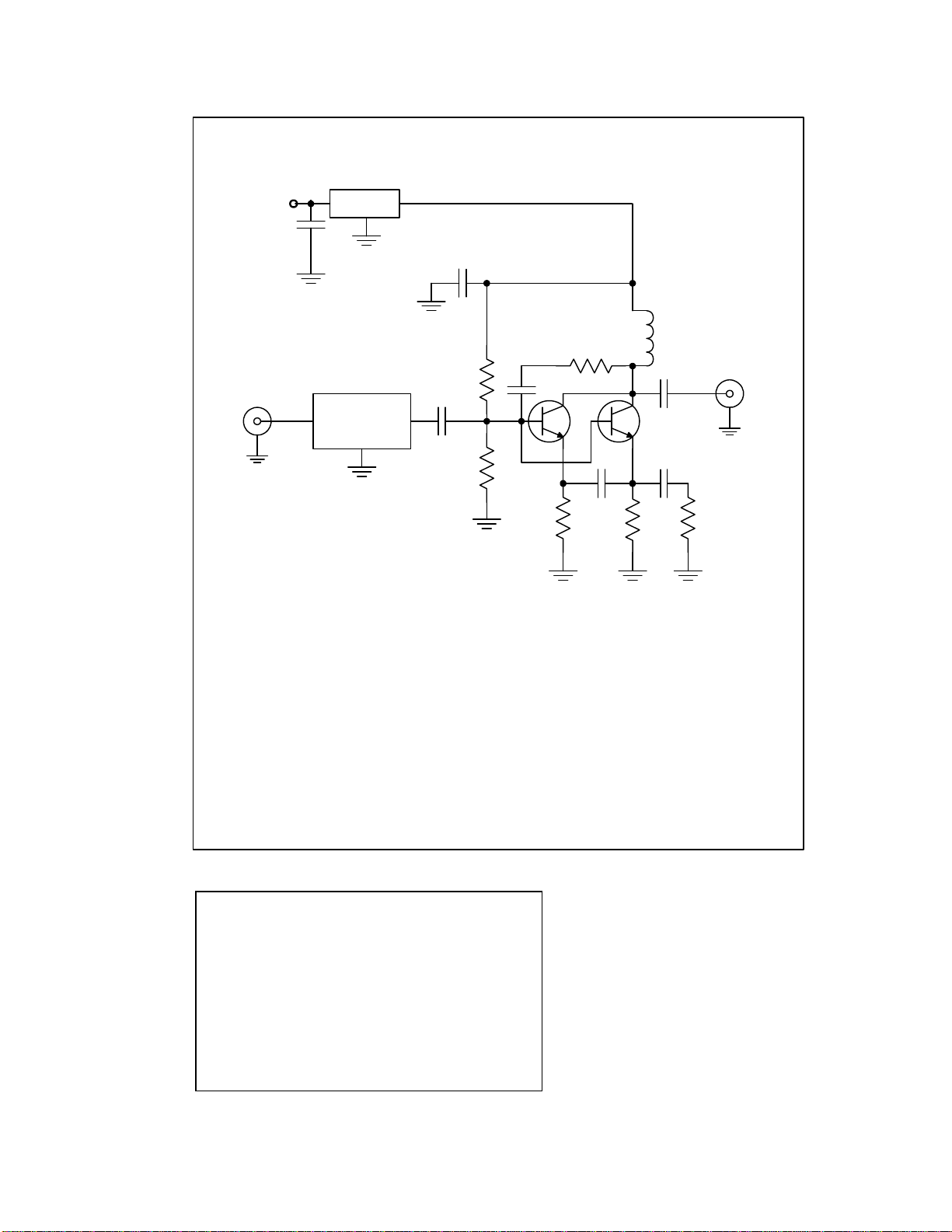
C1,2,3,4,5,6 0.1uF
C7 0.47uF
L1 2.2uH
R1 3.9K
R2 2.2K
R3,4 68
R5 12
R6 220
Q1,2 MPS5179
68.985 MHz
Xtal Filter
J1 C1
C2
C3
C4 C5
C6
J2
FL1
L1
R1
R2
R3 R4 R5
R6
Q1 Q2
78L05
C7
+12V
FT 920 Roofing Filter Mod W2VJN 3/22/08
Parts List
•Assembled Inrad 117 board
•2 RG-178 coax cables, 32” each
•2 male TMP connectors
•Red and black wire-18” each, #26
•2 stick-on standoffs
•2 tie wraps
© 2008 International Radio Corporation - 6 -
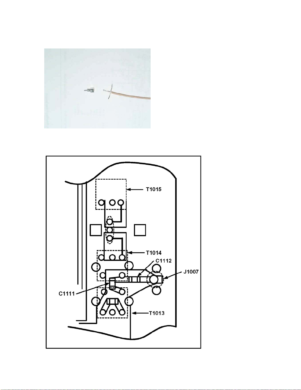
Figure 1. Preparation of coax cable.
Figure 2. Area for modification. Bottom of pc board.
© 2008 International Radio Corporation - 7 -

Figure 3. View of the board modification.
© 2008 International Radio Corporation - 8 -
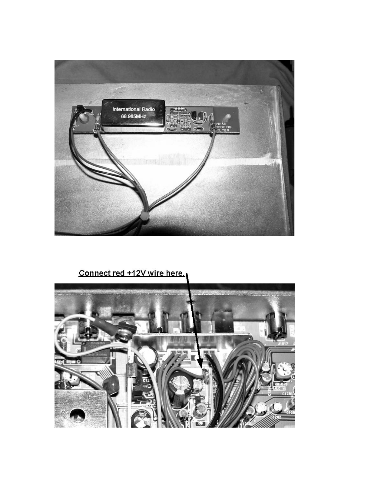
Figure 4. Mounting the modification board.
Figure 5. +12V connection point.
© 2008 International Radio Corporation - 9 -
Table of contents
Popular Water Filtration System manuals by other brands


Milli-Q
Milli-Q IX 7003 user manual

Beko
Beko CLEARPOINT S040 Installation & operation instructions

ControlOMatic
ControlOMatic MegaChlor Installation & operation manual

VEVOR
VEVOR CPF-2500 instruction manual

Lancaster
Lancaster 7-LXDAN-1 Installation, operating and service manual

Watts
Watts Big Bubba BB-S101 Installation, operation and maintenance manual

UV Pure Technologies
UV Pure Technologies UPSTREAM instruction manual

Vulcan-Hart
Vulcan-Hart 85MF Specifications

Clean Water
Clean Water Living Water VORTEXer user guide

Sentera Controls
Sentera Controls FIMX8 Mounting and operating instructions

EHEIM
EHEIM Professionel-3 2080 operating instructions

Master
Master MBA-MM-1040 Installation and operation manual