Master MBA-MM-1040 User manual

Installation and Operation Manual
MBA-MM-1040/10/13/1665
MULTI MEDIA FILTERS
with the
263/742 Logix Control Valve
MASTER
Water Conditioning Corp.
www.masterwater.com
June 2010

Table of Contents
Page
No.
Topic Description
1
Model # and Packaging
Packaging Information
2
Component Packaging
Description
Packaging Description
System Description
Valve Description
Filter Positioning
System Positioning
3
Multi Media Filter Tank Loading
Filling with Media
4
Logix 263/742 Control Valve
Attaching Valve to Tank
Figure 1 & Figure 2
5
Logix 263/742 Control Valve,
cont’d
Attaching Valve to Tank
Figure 1 & Figure 2
Service & Drain Piping
Drain Piping
Figure 3
6
Service & Drain Piping, cont’d
Drain Piping
Figure 3
7
System Schematic
Piping Layout
8
Electrical Supply
Electrical Requirements
Logix 263/742 Control Valve
Electrical Connection
Instructions on Logix 742
Electrical Connection
9
Filling Multi Media filter with
Water
Details for Filling Multi media filter
Tank with Water
10
Logix 263/742 Control Valve
Timer
Instructions on Logix 742
Timer Settings
11
Logix 263/742 Control Valve
Timer cont’d
Instructions on Logix 742
Timer Settings
Final Check
Final Installation Check
Specification Table
Flow rates and regeneration times
12
Troubleshooting
Symptom / Cause / Solution
13
ERR Troubleshooting
Error Troubleshooting
14
263/742 Valve Body Schematic
Parts View
15
Valve Body Parts List
Part Numbers List
16
Valve Parts List
Part Numbers List
17
Warranty
Warranty

1
Installation and Operating Instructions for
263/742 Logix
Top Mount Multi Media Filter
Model #:
_______ MBA-MM-1040 1.0 CF Multi Media Filter
_______ MBA-MM-10-1 1.5 CF Multi Media Filter
_______ MBA-MM-13-1 2.5 CF Multi Media Filter
_______ MBA-MM-1665-1 4.0 CF Multi Media Filter
NOTE: Product Change
The brine plug (1030334) was added, and the brine line
connection has an orange cap plug (191 Orange Cap). See
Figure below. DO NOT REMOVE CAPS OR PLUGS.

2
Shipping Carton Description / unit:
# of
cartons
Contents Description
1
Mineral tank
Distributor pipe installed
1
263/742
Logix control
valve
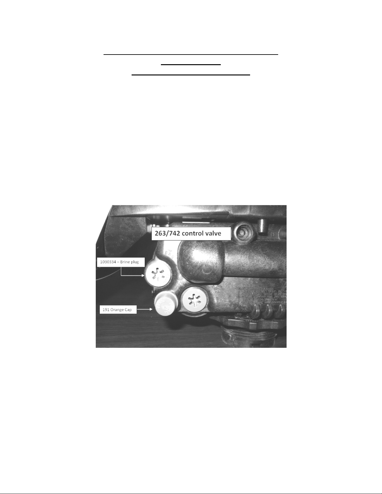
263/742 timer and backwash flow
control and bypass with 1” copper or
pvc connection
#1 Sand
Box
#0 Sand
Box
#45 Sand
Box
#0 Sand
Box
Philterkol
Box
Note: all units have a Vortech distributor and do not require
gravel.
System Description:
The multi media filter tank has a Logix top mounted automatic
control valve with an electronic time clock to initiate regeneration.
The Logix Valve is constructed of non-corrosive Norylmaterial and
is rated at a maximum working water pressure of 100 psi. It uses a
742 microprocessor based timer to actuate regeneration in the
following ways:
a.Manual regeneration button to start an emergency
regeneration
b.Regeneration day setting
NOTE: THIS FILTER IS NOT INTENDED TO BE USED FOR TREATING WATER THAT
IS MICROBIOLOGICALLY UNSAFE OR OF UNKNOWN QUALITY WITHOUT
ADEQUATE DISINFECTION WHETHER BEFORE OR AFTER THE SYSTEM.
Multi Media Filter Positioning:
1. Place Multi Media Filter in desired position, far enough from walls
and other obstructions to allow for servicing the unit.
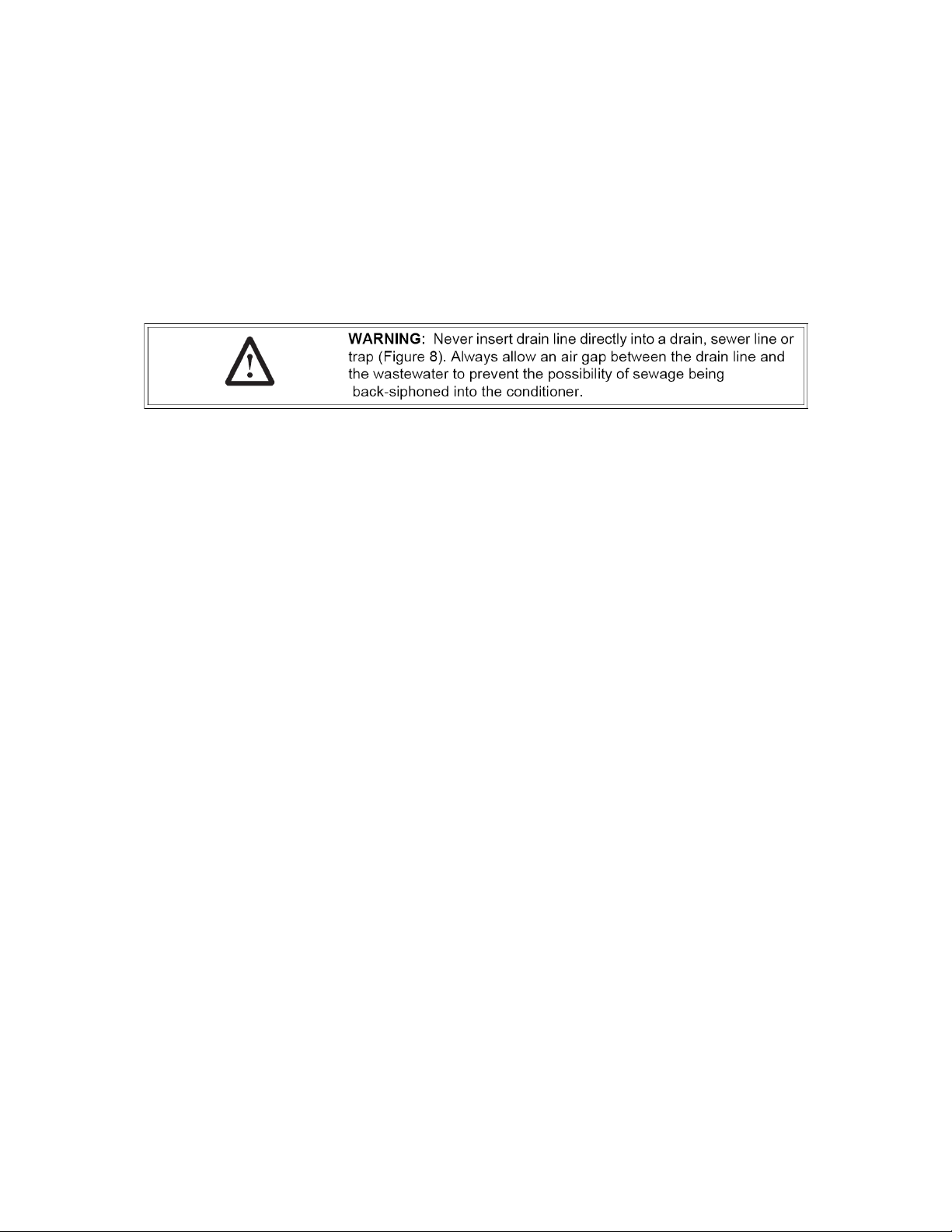
2. Place the Multi Media Filter within reasonable access to a
grounded 115V/60 HZ circuit and a legal drain line connection.

3
Multi Media Filter Tank Loading:
1. Remove yellow caplug from top of tank. DO NOT CUT white
riser tube. Tube was prefitted at the factory.
2. The distributor is permantly attached to the vortech----centering
is not necessary.
3. Cover the top opening of the distributor pipe before filling the
tank with media.
Model #
Gravel
1 Sand
0 Sand
45 Sand
0 Sand
Philterkol
MBA-MM-1040
n/a
12 lbs.
8 lbs.
25 lbs.
17 lbs.
13 lbs.
MBA-MM-10
n/a
20 lbs.
12 lbs.
37 lbs.
25 lbs.
19 lbs.
MBA-MM-13
n/a
25 lbs.
16 lbs.
50 lbs.
35 lbs.
25 lbs.
MBA-MM-1665
n/a
50 lbs.
50 lbs.
100 lbs.
80 lbs.
50 lbs.
4. Pour all filter media provided with the unit into the top of the tank.
See page one for your specific model number of unit to
determine the amount of media to load into the mineral tank.
5. Remove the material used to cover the top opening of the
distributor pipe.
Logix Control Valve:
Philterkol
0 Sand
0 Sand
45 Sand
1 Sand

4
1. When facing the front of the Logix timer, the inlet connection
(Figure 1) is located on the left and the outlet connection is on the
right. The control valve's inlet and outlet connections are either
1” copper or PVC equipped with gasket and nut.
Figure 1
Install the 263 bypass valve (See Figure 2) with inlet and outlet
handles facing upward. Place gasket into nut and secure 1” copper
or PVC tail piece with a nut. Repeat the procedure for the outlet
connection.
DO NOT OVERTIGHTEN THE NUT.
Figure 2
2. The control valve's drain connection is 3/4" npt and is located on
the back of the control valve.
3. Turn the control valve upside down and ensure that the control
valve distributor o'rings are in place. Use silicone lubricant on
the o'rings.
4. Place the control valve onto the distributor pipe.
5. Thread the control valve hand tight to 20 foot pounds!

5
DO NOT OVERTIGHTEN!
**DO NOT USE PETROLEUM!**
**USE ONLY SILICONE **
Service and Drain Piping:
1. Pipe Multi Media Filter into the service lines .The inlet and outlet
connections of the control valve are 1” copper or PVC and are
located on the back of the valve body. As you face the timer the
inlet is on the left and the outlet is on the right. Always follow
local plumbing codes when installing our water treatment
equipment.
2. If sweat fittings are used, be sure soldering is done in such a
manner as not to allow heat to reach the control valve or bypass.
(If Schedule 80 PVC is used make sure to follow the proper
primer and solvent instructions.)
3. The drain line connection is located on the back of the valve as
you face the timer. It is recommended you install a ¾” union on
the drain line for servicing. The drain line must be of adequate
size to allow for full regeneration flow.
Figure 3
•The control valve drain connection is 3/4" npt.

6
•Never decrease the drain piping size to below ¾”
•Maximum drain line length is 30 feet.
•Maximum drain line height is 6 feet above the
control valve.
•The drain line must be piped to an open air gap
(See Figure 3)
•Always follow local plumbing codes.

7
Well Tank
Untreated
water from well
NOTE: All Master Water Conditioners must be
installed after the well tank or water meter if its
public water supply.
Master Water
Conditioner
Air Gap Drain
Treated water
Untreated to outside
224 Shoemaker Rd.
Pottstown, PA 19464
Typical Piping Layout

8
Electrical Requirements:
Always follow all local electrical codes when installing our water
treatment equipment.
1. Provide an 115v/60Hz properly grounded dedicated electrical
Outlet. (It’s very important that the polarity be correct)
Avoid using outlets that are switch controlled.
2. Maximum amperage required is 5 amps.
3. Make sure the electrical service provides power 24 hours per day.
We recommend installing a surge protector to protect unit from
power surges, which are not covered by warranty.
Logix Control Valve Electrical Connection:
Note: Do not touch the wiring harness between the Logix
timer and the motor, it’s positioning is critical and therefore
already installed at the factory.
1. Remove plastic control valve cover by spreading sides while
lifting.
2. Plug transformer into back of timer following existing wires.
3. Plug transformer into a properly grounded 120V/60 HZ electrical
outlet.
4. The screen will now display “263” then the “Time of Day”.

9
Filling Multi Media Filter with Water:
Figure 4
1. Push the FOR REGENERATION button (Figure 4) on the
controller down for 5 seconds. This will initiate a manual
regeneration. You will notice a flashing hour glass during
regeneration.
The controller will indicate that the motor is turning the camshaft
to cycle C1 (BACKWASH). The controller will indicate the total
regeneration time remaining. Filling tank in this position allows air
to escape from drain.
Open the bypass inlet valve ¼ turn and allow water to flow into the
mineral tank at a slow rate.
Warning: IF WATER ENTERS THE TANK TOO FAST, ALL THE
MEDIA WILL BE FLUSHED TO DRAIN DURING START UP.
2. When water is running steadily at the drain, open the bypass
valve’s inlet and outlet to their maximum position.
3. Simultaneously press the SET and UP buttons on the controller
for 1 second then release, the motor will advance the cam to C2.
4. Once C2 is displayed simultaneously press the SET and UP
buttons on the controller for 1 second then release, the motor will
advance the cam to C3.
5. Repeat this procedure until the timer enters the C7 (FAST RINSE)
position. The multi media filter will go through the rinsing cycle
and then automatically advance to (REGENERATION
COMPLETE) C0 and Time of Day will be displayed. This is
treated water.

10
Logix Control Valve Timer Settings:
Note: The control valve is set at the factory. You only need to set
the time of day and regeneration time if required, which is preset
at 1 am.
Figure 5
Time of Day Setting
1) Press the SET button. The screen will show the Time of Day
in blinking numbers.
2) To change the Time of Day, use the UP or DOWN arrows.
3) Press the SET button.
Day of Week Setting
1) Press the SET button. The screen will show the Day of Week
in blinking triangle.
2) To change the Day of Week, use the UP or DOWN arrows.
3) Press the SET button.
Time of Regeneration Setting (the factory default is 1 AM)
1) Press the SET button. The screen will show the Time of
Regeneration in blinking numbers.
2) To change the Time of Regeneration, use the UP or DOWN
arrows.
3) Press the SET button.

11
Regeneration Frequency Setting (the factory default is 7)
1) Press the SET button. The screen will show the Regeneration
frequency in blinking numbers.
2) To change the number, use the UP or DOWN arrows.
3) Press the SET button.
If you wish to regenerate on certain days ot the week, do
the following:
a. First, do steps above, but set at zero.
b. Press SET button until you reach the day you wish
to regenerate.
c. Press the UP or Down arrows to set the day.
d. Press the SET button to lock the day in.
e. Repeat process to select the next day of
regeneration.
NOTE: The days of Regeneration will be highlighted on the
screen.
Final Check:
1. Inspect the treated water to assure that the media fines (color)
have been flushed from the unit. Make sure the drain line
connection meets all plumbing codes and that the drain line size
can handle the backwash flow rate of the multi media filter.
2. Make sure the Inlet and Outlet on bypass valve are open.
3. Make sure the control valve timer is plugged into an electrical
outlet with power 24 hours per day.
4. Check all piping for leaks.
Specification Reference Table
Model #
Conditioned
Water Flow
Rate
Backwash
Required
Backwash
Timing
Slow Rinse
Timing
Fast Rinse
Timing
MBA-MM-1040
5.0 gpm
6.0 gpm
15
Minutes
0 Minutes
10 Minutes
MBA-MM-10
5.0 gpm
6.0 gpm
15
Minutes
0 Minutes
10 Minutes
MBA-MM-13
8.0 gpm
10.0 gpm
15
Minutes
0 Minutes
10 Minutes
MBA-MM-1665
12.0 gpm
15.0 gpm
15
Minutes
0 Minutes
10 Minutes

12
Troubleshooting
Symptom: Water conditioner fails to regenerate. Dirty water.
Possible Cause
Solution
Power supply to 742 control has
been interrupted.
Determine reason for power
interruption and correct. Reset time of
day.
Water pressure lost.
Restore water pressure.
Corrupted programming of 742
Logix timer.
Reprogram timer assembly.
Defective 742 Logix timer.
Replace timer assembly.
Manual bypass valve is open.
Close manual bypass valve.
Leak at riser pipe seal.
Insure that riser pipe is properly
sealed at o’ring seal. Inspect pipe for
cracks.
Symptom: Loss of Media to Drain
Possible Cause
Solution
No flow control installed in drain
line.
Install drain line flow control.
Symptom: Leak to Drain
Possible Cause
Solution
No flow control installed in drain
line.
Install drain line flow control.
Insufficient water pressure.
Increase water pressure above 25
psig (172kPa) minimum.
Damaged valve disk or obstruction
in valve disk.
Inspect and if damaged, replace all
valve disks or remove obstruction.
Symptom: Loss of Water Pressure
Possible Cause
Solution
Fouled filter media bed due to iron
accumulation.
Clean control valve and rebed mineral
tank with new media.
Slots in riser pipe or laterals are
filled with media fines.
Inspect and clean distributor pipe slots
as needed.

13

14

15

16

12 YEAR LIMITED WARRANTY
As of November 2022
This Residential Water Conditioner is warranted for a period of one year from date of
purchase by first user against defects in materials and workmanship. In addition, the complete
control valve is warranted for five years. The control valve body (excluding internals and electrical
parts) is warranted for six years. The mineral tank, plastic brine tank or cabinet tank (excluding
mineral) is warranted against rust, corrosion or bursting for a period of twelve years from date of
manufacture. Except, as specifically set forth in this paragraph, Master Water Conditioning
Corporation makes no other warranties, express or implied.
This warranty shall be void if the conditioner is moved from the place of original installation,
or if damage is caused by misuse, misapplication, accident, freezing, flood, fire or if not installed in
accordance with instructions furnished by Master Water Conditioning Corporation.
This warranty shall be void in the event of damages from external sources or where the
conditioner has been operated at pressure in excess of 100 pounds per square inch or at a temperature
greater than 100 degrees F. or less than 32 degrees F. Incidental costs or consequential damages are
not covered by this warranty.
All defective parts shall be returned prepaid to Master Water Conditioning Corporation for
inspection. Master shall not be liable for labor charges other than Master factory repairs.
This warranty gives you specific legal rights, and you may have other rights which vary from
state to state. Some states do not allow limitations on duration of implied warranties or exclusion of
incidental or consequential damages, so the above limitations may not apply to you.
All claims must be submitted in writing to Master Water Conditioning Corporation at 224
Shoemaker Road, Pottstown, Pennsylvania 19464 within thirty (30) days from the discovery of the
defect. Master Water Conditioning Corporation thereafter will correct defective parts and
workmanship or rusting, corrosion or bursting within sixty (60) days.
224 Shoemaker Rd. Pottstown, Pa. 19464
MASTER
Water Conditioning Corp.
This manual suits for next models
3
Other Master Water Filtration System manuals
Popular Water Filtration System manuals by other brands

Miele professional
Miele professional PG 8595 operating instructions

Excel
Excel XLERATOR 40525 owner's manual

Contech
Contech VortSentry HS Series Maintenance Guide

NTZ
NTZ ALH series instruction manual

Blanca
Blanca Atmospheric Water Maker user manual

Hague Quality Water
Hague Quality Water WaterMax H5000 Owner's manual and installation guide