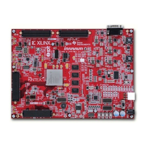
Inrevium TB-7V-2000T-LSI Instructions for use

TB-7V-2000T-LSI Hardware User Manual
1
Rev.1.03
TB-7V-2000T-LSI
Hardware User Manual
Rev.1.03

TB-7V-2000T-LSI Hardware User Manual
2
Rev.1.03
Revision History
Version
Date
Description
Publisher
Rev.1.00
2013/04/25
Release version
Amano
Rev.1.01
2013/06/21
Modify Table 8-28,Table 8-29,Figure 8-33
Amano
Rev.1.02
2013/08/02
Modify Table 8-7,Table 8-15,Table 8-23,Table 9-7,Table 9-17,
Table 9-19
Amano
Rev.1.03
2013/08/12
Modify Table 9-19
Amano

TB-7V-2000T-LSI Hardware User Manual
3
Rev.1.03
Table of Contents
1. Related Documents and Accessories ....................................................................................... 14
2. Overview.................................................................................................................................... 14
3. Feature ...................................................................................................................................... 15
4. Block Diagram........................................................................................................................... 16
4.1.Block diagram of TB-7V-2000T-LSI.......................................................................................... 16
4.2. FPGA Bank Assgin................................................................................................................... 17
4.2.1. Bank assign of XC7V2000T ............................................................................................. 17
4.2.2. Bank assignments of XC7K325T...................................................................................... 18
5. External View of the Board........................................................................................................ 19
6. Board Specifications.................................................................................................................. 20
7. Power Supply/Clock (Virtex-7/Kintex-7).................................................................................... 21
7.1. Power Supply Structure............................................................................................................ 21
7.1.1. Power Input....................................................................................................................... 22
7.1.2. Power Supply Status Checking ........................................................................................ 23
7.1.3. Kintex-7 FPGA Bank Voltage Selection............................................................................ 25
7.1.3.1. XADC Power Supply on Virtex-7 .................................................................................. 27
7.1.3.2. XADC Power Supply on Kintex-7 ................................................................................. 28
7.1.4. PM Bus Interface (CN5).................................................................................................... 29
7.2. Clock Source............................................................................................................................ 30
7.3. Kintex-7 MGT Reference Clock Selector ................................................................................. 34
8. Virtex-7 Interface....................................................................................................................... 35
8.1. DDR3 SDRAM.......................................................................................................................... 35
8.2. QTH Connector ........................................................................................................................ 39
8.2.1. QTH1 Power Supply Pinout.............................................................................................. 39
8.2.2. QTH2 Power Supply Pinout.............................................................................................. 45
8.2.3. QTH3 Power Supply Pinout.............................................................................................. 50
8.3. PCI Express / GTX Connector ................................................................................................. 55
8.4. USB3.0..................................................................................................................................... 62
8.4.1. USB3.0 TYPE-B Connector.............................................................................................. 64
8.4.2. I2S Connector................................................................................................................... 64
8.4.3. SPI Connector and SPI Flash Memory............................................................................. 65
8.4.4. I2C Interface ..................................................................................................................... 66
8.4.5. RS232C Connector........................................................................................................... 67
8.4.6. IFSEL Jumpers................................................................................................................. 67
8.4.7. USB JTAG Connector....................................................................................................... 68
8.4.8. PMODE Jumpers.............................................................................................................. 69
8.4.9. CLK Jumper...................................................................................................................... 70
8.4.10. OTG_ID............................................................................................................................. 70
8.4.11. Reset................................................................................................................................. 71
8.5. DVI............................................................................................................................................ 72
8.5.1. DVI_Rx.............................................................................................................................. 73
8.5.2. DVI_Tx.............................................................................................................................. 74
8.5.3. DVI_Rx- DVI_Tx Connections.......................................................................................... 76

TB-7V-2000T-LSI Hardware User Manual
4
Rev.1.03
8.6. RS-232C................................................................................................................................... 78
8.7. PinHeader ................................................................................................................................ 80
8.8. DipSW ...................................................................................................................................... 82
8.9. PushSW.................................................................................................................................... 84
8.10. Rotary SW ............................................................................................................................ 85
8.11. LED....................................................................................................................................... 86
8.12. Single Digit LED ................................................................................................................... 88
8.13. XADC Pin Header................................................................................................................. 90
8.14. Battery Control...................................................................................................................... 91
8.15. Virtex-7 Config Micro SD/NAND Flash................................................................................. 92
9. Kintex-7 Interfae........................................................................................................................ 93
9.1. QTH Connector ........................................................................................................................ 93
9.1.1. QTH4 Power Supply Pins................................................................................................. 95
9.1.2. Switchover of desctination (Kintex-7/CN33) to which the QTH4 connector is connected
100
9.1.3. QTH5 Power Supply Pinout............................................................................................ 102
9.1.4. Switchover of desctination (Kintex-7/IIC) to which the QTH5 connector is connected .. 107
9.2. FMC Connector...................................................................................................................... 109
9.2.1. HPC Connector (High-Pin Count)....................................................................................110
9.3. RS-232C..................................................................................................................................118
9.4. DipSW .................................................................................................................................... 120
9.5. PushSW.................................................................................................................................. 121
9.6. LED......................................................................................................................................... 122
9.7. XADC Dedicated Pin Header................................................................................................. 123
9.8. Battery Control ....................................................................................................................... 125
9.9. Quad SPI Flash...................................................................................................................... 126
10. Virtex-7 and Kintex-7 Interconnection..................................................................................... 127
11. Generating a Kintex-7 Configuration File................................................................................ 136
11.1. How to Generate a Configuration File (bit file)................................................................... 136
11.2. Required Configuration Time.............................................................................................. 137
11.3. Unused Pin Settings........................................................................................................... 137
11.4. How to Generate a Configuration File (mcs file) ................................................................ 138
11.5. Loading a Configuration File to Flash Memory .................................................................. 143
12. QTH-FMC Conversion Board.................................................................................................. 148
12.1. Power Supply to FMC Card................................................................................................ 149
12.1.1. 12V Power Supply.......................................................................................................... 149
12.1.2. 3.3V Power Supply......................................................................................................... 150
12.1.3. VADJ Power Supply........................................................................................................ 151
12.2. How to Attach Spacers ....................................................................................................... 152
13. Default Switch Settings ........................................................................................................... 153

TB-7V-2000T-LSI Hardware User Manual
5
Rev.1.03
List of Figures
Figure 4-1 Block Diagram ................................................................................................................ 16
Figure 4-2 Bank Assignments of XC7V2000T.................................................................................. 17
Figure 4-3 Bank Assignments of XC7K325T.................................................................................... 18
Figure 5-1 Component Side............................................................................................................. 19
Figure 5-2 Solder Side ..................................................................................................................... 19
Figure 7-1 Power Supply Structure.................................................................................................. 22
Figure 7-2 Power Supply Structure.................................................................................................. 22
Figure 7-3 Power Status LEDs (Virtex-7/Spartan-3AN) ................................................................... 23
Figure 7-4 Power Sutatus LEDs (Kintex-7)...................................................................................... 24
Figure 7-5 Kintex-7 Banks and Peripheral Devices......................................................................... 25
Figure 7-6 Bank Voltage Setting Location on FPGA (Kintex-7) ....................................................... 26
Figure 7-7 VCCADC/VREFP Voltage Selection on Virtex-7 ............................................................ 27
Figure 7-8 VCCADC/VREFP Selection Location on Virtex-7........................................................... 27
Figure 7-9 VCCADC/VREFP Selection on Kintex-7 ........................................................................ 28
Figure 7-10 VCCADC/VREFP Selection Location on Kintex-7........................................................ 29
Figure 7-11 Clock Structure.............................................................................................................. 31
Figure 7-12 Strucure of Kintex-7 MGT Reference Clock Selector IC Peripherals........................... 34
Figure 8-1 Onboard DDR3 SDRAMs ............................................................................................... 35
Figure 8-2 DDR3 SDRAM Connections........................................................................................... 36
Figure 8-3 Virtex-7 QTH Connector ................................................................................................. 39
Figure 8-4 PCI Express Connector [CN23] / GTX Connector [CN24] ............................................. 55
Figure 8-5 USB3.0 Structure............................................................................................................ 62
Figure 8-6 USB3.0 TYPE-B Connector............................................................................................ 64
Figure 8-7 I2S Connector................................................................................................................. 64
Figure 8-8 Onboard SPI Connector ................................................................................................. 65
Figure 8-9 Onboard SPI Flash Memory........................................................................................... 65
Figure 8-10 I2C Interface Structure.................................................................................................. 66
Figure 8-11 Onboard I2C Interface .................................................................................................. 66
Figure 8-12 RS232C Connector....................................................................................................... 67
Figure 8-13 Onboard IFSEL Jumpers.............................................................................................. 67
Figure 8-14 Onboard USB JTAG Connector.................................................................................... 68
Figure 8-15 Onboard PMODE Jumpers........................................................................................... 69
Figure 8-16 Onboard CLK Jumper [JP54]........................................................................................ 70
Figure 8-17 Onboard OTG ID Jumper [JP55].................................................................................. 70
Figure 8-18 Reset Structure............................................................................................................. 71
Figure 8-19 Onboard Reset Circuits ................................................................................................ 71
Figure 8-20 DVI Interface Structure (Rx/Tx) .................................................................................... 72
Figure 8-21 Onboard DVI Interface (Rx/Tx)..................................................................................... 72
Figure 8-22 DVI Interface Structure (Rx).......................................................................................... 73
Figure 8-23 DVI Interface Structure (Tx).......................................................................................... 74
Figure 8-24 SW5/SW6 Structure...................................................................................................... 76
Figure 8-25 Onboard SW5 and SW6............................................................................................... 76
Figure 8-26 RS-232C Structure........................................................................................................ 78
Figure 8-27 Onboard D-sub Connector............................................................................................ 78
Figure 8-28 Onboard FPGA Switching Jumpers.............................................................................. 79
Figure 8-29 PinHeader Structure ..................................................................................................... 80

TB-7V-2000T-LSI Hardware User Manual
6
Rev.1.03
Figure 8-30 Onboard PinHeaders.................................................................................................... 80
Figure 8-31 Virtex-7 DIPSW Structure............................................................................................. 82
Figure 8-32 Onboard DIPSWs......................................................................................................... 82
Figure 8-33 Virtex-7 PushSW Sructure............................................................................................ 84
Figure 8-34 Onboard PushSWs....................................................................................................... 84
Figure 8-35 Rotary SW Structure..................................................................................................... 85
Figure 8-36 Onboard Rotary SW ..................................................................................................... 85
Figure 8-37 Virtex-7 LED Structure.................................................................................................. 86
Figure 8-38 Onboard LEDs.............................................................................................................. 86
Figure 8-39 Single Digit LED(LED64) Structure............................................................................... 88
Figure 8-40 Onboard Single Digit LEDs........................................................................................... 88
Figure 8-41 Virtex-7 XADC PinHeader Structure............................................................................. 90
Figure 8-42 Onboard XADC PinHeader........................................................................................... 90
Figure 8-43 Virtex-7 Battery Structure.............................................................................................. 91
Figure 8-44 Onboard Battery ........................................................................................................... 91
Figure 8-45 Virtex-7 Configuration Circuit Structure ........................................................................ 92
Figure 9-1 Kintex-7 QTH Connector ................................................................................................ 93
Figure 9-2 Bank Voltage Setting Location on FPGA (Kintex-7) ....................................................... 94
Figure 9-3 Structure of switchover of destination (Kintex-7/IIC) to which the QTH4 connector is
connected................................................................................................................................ 100
Figure 9-4 Structure of switchover of destination (Kintex-7/IIC) to which the QTH5 connector is
connected................................................................................................................................ 107
Figure 9-5 HPC (High-Pin Count) Pin Assignments....................................................................... 109
Figure 9-6 LPC (Low-Pin Count) Pin Assignments........................................................................ 109
Figure 9-7 SDA,SCL,GA1/0 TDI/TDO Circuit Structure..................................................................116
Figure 9-8 PG_C2M Circuit Structure .............................................................................................116
Figure 9-9 RS-232C Circuit Structure .............................................................................................118
Figure 9-10 Onboad D-sub Connector............................................................................................118
Figure 9-11 Onboard FPGA Connectivity Jumpers.........................................................................119
Figure 9-12 Onboad Kintex-7 dedicated DIPSW ........................................................................... 120
Figure 9-13 Kintex-7 Dedicated PushSW Structure....................................................................... 121
Figure 9-14 Onboard PushSWs..................................................................................................... 121
Figure 9-15 Kintex-7 Dedicated LED Structure.............................................................................. 122
Figure 9-16 Onboard Kintex-7 Dedicated LEDs ............................................................................ 122
Figure 9-17 Kintex-7 XADC Dedicated PinHeader Sructure ......................................................... 123
Figure 9-18 Onboard XADC Dedicated PinHeader ....................................................................... 123
Figure 9-19 Kintex-7 Battery Structure........................................................................................... 125
Figure 9-20 Onboard Kintex-7 Battery........................................................................................... 125
Figure 9-21 QSPI Flash Memory Structure.................................................................................... 126
Figure 10-1 FPGA Interconnections............................................................................................... 127
Figure 11-1 Process Properties Window........................................................................................ 136
Figure 11-2 Options available when generating a bit file ............................................................... 136
Figure 11-3 Changing Configuration Time ..................................................................................... 137
Figure 11-4 Unused Pin Settings ................................................................................................... 137
Figure 11-5 Generating a Configurtion File on ISE........................................................................ 138
Figure 11-6 Warning Message....................................................................................................... 138
Figure 11-7 iMPACT Window - 1.................................................................................................... 139

TB-7V-2000T-LSI Hardware User Manual
7
Rev.1.03
Figure 11-8 iMPACT Window - 2.................................................................................................... 139
Figure 11-9 iMPACT Window - 3.................................................................................................... 140
Figure 11-10 iMPACT Window - 4.................................................................................................. 140
Figure 11-11 iMPACT Window - 5 .................................................................................................. 141
Figure 11-12 iMPACT Window - 6.................................................................................................. 141
Figure 11-13 iMPACT Window - 7.................................................................................................. 141
Figure 11-14 iMPACT Window - 8.................................................................................................. 141
Figure 11-15 iMPACT Window - 9.................................................................................................. 142
Figure 11-16 iMPACT Window –10............................................................................................... 142
Figure 11-17 Onboard JTAG Connector ........................................................................................ 143
Figure 11-18 Loading a Configuration File to Device (1) ............................................................... 143
Figure 11-19 Loading a Configuration File to Device (2) ............................................................... 144
Figure 11-20 Loading a Configuration File to Device (3) ............................................................... 144
Figure 11-21 Loading a Configuration File to Device (4) ............................................................... 145
Figure 11-22 Loading a Configuration File to Device (5) ............................................................... 145
Figure 11-23 Loading a Configuration File to Device (6) ............................................................... 146
Figure 11-24 Loading a Configuration File to Device (7) ............................................................... 146
Figure 11-25 Loading a Configuration File to Device (8) ............................................................... 147
Figure 11-26 Onboard Reconfiguration Switch.............................................................................. 147
Figure 11-27 Configuration Status.................................................................................................. 147
Figure 12-1 QTH-FMC Conversion Boards ................................................................................... 148
Figure 12-2 An Example of QTH-FMC Connection........................................................................ 149
Figure 12-3 How to Attach Spacers................................................................................................ 152
Figure 13-1 Default Switch Settings on Component Side of the Board......................................... 153

TB-7V-2000T-LSI Hardware User Manual
8
Rev.1.03
List of Tables
Table 7-1 Power Status LEDs (Virtex-7/Spartan-3AN)..................................................................... 23
Table 7-2 Power Status LED (Kintex-7)............................................................................................ 24
Table 7-3 Kintex-7 Bank –Peripheral Device Voltage Selection...................................................... 26
Table 7-4 VCCADC/VREFP Voltage Selection on Virtex-7.............................................................. 27
Table 7-5 VCCADC/VREFP Selection on Kintex-7.......................................................................... 28
Table 7-6 Clock Source.................................................................................................................... 31
Table 7-7 Kintex-7 MGT Reference Clock Configuration Table ....................................................... 34
Table 7-8 SW26 Setting Table.......................................................................................................... 34
Table 8-1 DDR3 SDRAM and Virtex-7 Pin Assignment Table.......................................................... 37
Table 8-2 QTH1 B54 Pin Assignments............................................................................................. 39
Table 8-3 QTH1 B55 Pin Assignments............................................................................................. 40
Table 8-4 QTH1 B56 Pin Assignments............................................................................................. 40
Table 8-5 QTH1 B57 Pin Assignments............................................................................................. 40
Table 8-6 QTH1 B58 Pin Assignments............................................................................................. 40
Table 8-7 QTH1 B59 Pin Assignments............................................................................................. 41
Table 8-8 QTH1 B60 Pin Assignments............................................................................................. 41
Table 8-9 QTH1 Connector (CN20) Pin Assignments...................................................................... 42
Table 8-10 QTH2 B54 Pin Assignments........................................................................................... 45
Table 8-11 QTH2 B55 Pin Assignments........................................................................................... 45
Table 8-12 QTH2 B56 Pin Assignments........................................................................................... 45
Table 8-13 QTH2 B57 Pin Assignments........................................................................................... 46
Table 8-14 QTH2 B58 Pin Assignments........................................................................................... 46
Table 8-15 QTH2 B59 Pin Assignments........................................................................................... 46
Table 8-16 QTH2 B60 Pin Assignments........................................................................................... 46
Table 8-17 QTH2 Connector (CN21) Pin Assignments.................................................................... 47
Table 8-18 QTH3 B54 Pin Assignments........................................................................................... 50
Table 8-19 QTH3 B55 Pin Assignments........................................................................................... 50
Table 8-20 QTH3 B56 Pin Assignments........................................................................................... 50
Table 8-21 QTH3 B57 Pin Assignments........................................................................................... 50
Table 8-22 QTH3 B58 Pin Assignments........................................................................................... 51
Table 8-23 QTH3 B59 Pin Assignments........................................................................................... 51
Table 8-24 QTH3 B60 Pin Assignments........................................................................................... 51
Table 8-25 QTH3 Connector (CN22) Pin Assignments.................................................................... 52
Table 8-26 Virtex-7 - PCI Express Connector [CN23] Signal Connections...................................... 56
Table 8-27 PCI Express Connector [CN23] Pin Assignments.......................................................... 57
Table 8-28 Signal Connections between Virtex-7 and GTX Connector [CN24]............................... 59
Table 8-29 GTX Connector [CN24] Pin Assignments ...................................................................... 60
Table 8-30 USB3.0 Controller Pin Assignments............................................................................... 63
Table 8-31 I2S Connector Pin Assignments..................................................................................... 64
Table 8-32 SPI Connector Pin Assignments .................................................................................... 65
Table 8-33 SW PinAssignments for I2C Device Configuration........................................................ 66
Table 8-34 Jumper Settings for FPGAAccess................................................................................. 66
Table 8-35 RS232C Connector Pin Assignments ............................................................................ 67
Table 8-36 IFSEL Jumper Settings .................................................................................................. 67
Table 8-37 USB JTAG Connector Pin Assignments......................................................................... 68
Table 8-38 RTCK SEL Jumper Settings........................................................................................... 68

TB-7V-2000T-LSI Hardware User Manual
9
Rev.1.03
Table 8-39 PMODE Jumper Settings............................................................................................... 69
Table 8-40 CLK Jumper [JP54] Settings.......................................................................................... 70
Table 8-41 OTG ID Jumper [JP55] Settings..................................................................................... 70
Table 8-42 DVI Rx Pin Assignments ................................................................................................ 73
Table 8-43 DVI Tx Pin Assignments................................................................................................. 75
Table 8-44 DVI_Rx- DVI_Tx Connections........................................................................................ 77
Table 8-45 FPGA Signal Connections.............................................................................................. 78
Table 8-46 FPGA(Virtex-7) Switching Jumper Settings ................................................................... 79
Table 8-47 FPGA(Kintex-7) Switching Jumper Setting.................................................................... 79
Table 8-48 PinHeader (CN25) Pin Assignments.............................................................................. 81
Table 8-49 PinHeader (CN26) Pin Assignments.............................................................................. 81
Table 8-50 Virtex-7 DIPSW Pin Assignments................................................................................... 83
Table 8-51 Virtex-7 PushSW Pin Assignments ................................................................................ 84
Table 8-52 Rotary SW Pin Assignments .......................................................................................... 85
Table 8-53 Rotary SW Output Signal Values ................................................................................... 85
Table 8-54 Virtex-7 LED Pin Assignments ....................................................................................... 87
Table 8-55 Single Digit LED(LED64) Pin Assignments.................................................................... 89
Table 8-56 Single Digit LED(LED65) Pin Assignments.................................................................... 89
Table 8-57 Virtex-7 XADC PinHeader Pin Assignments .................................................................. 90
Table 9-1 Voltage Selection for Kintex-7 Banks and Peripheral Devices......................................... 94
Table 9-2 QTH4 B54 Pin Assignments............................................................................................. 95
Table 9-3 QTH4 B55 Pin Assignments............................................................................................. 95
Table 9-4 QTH4 B56 Pin Assignments............................................................................................. 95
Table 9-5 QTH4 B57 Pin Assignments............................................................................................. 95
Table 9-6 QTH4 B58 Pin Assignments............................................................................................. 96
Table 9-7 QTH4 B59 Pin Assignments............................................................................................. 96
Table 9-8 QTH4 B60 Pin Assignments............................................................................................. 96
Table 9-9 QTH4 Connector (CN31) Pin Assignments...................................................................... 97
Table 9-10 Switchover of desctination (Kintex-7/CN33) to which the QTH4 connector is connected
................................................................................................................................................ 100
Table 9-11 IIC Pullup On/OFF Switchover ..................................................................................... 101
Table 9-12 QTH5 B54 Pin Assignments......................................................................................... 102
Table 9-13 QTH5 B5 Pin Assignments........................................................................................... 102
Table 9-14 QTH5 B5 Pin Assignments........................................................................................... 102
Table 9-15 QTH5 B57 Pin Assignments......................................................................................... 102
Table 9-16 QTH5 B5 Pin Assignments........................................................................................... 103
Table 9-17 QTH5 B59 Pin Assignments......................................................................................... 103
Table 9-18 QTH5 B6 Pin Assignments........................................................................................... 103
Table 9-19 QTH5 Connector (CN32) Pin Assignments.................................................................. 104
Table 9-20 Switchover of destination (Kintex-7/CN33) to which the QTH5 connector is connected
................................................................................................................................................ 107
Table 9-21 IIC Pullup On/Off Switchover........................................................................................ 108
Table 9-22 HPC Connector (CN34) Pin Assignments.....................................................................111
Table 9-23 PG_C2M,PG_M2C,PRSNT_M2C_L Level Settings .....................................................116
Table 9-24 FPGA Signal Connections.............................................................................................118
Table 9-25 FPGA (Virtex-7) Connectdivity Jumper Settings ...........................................................119
Table 9-26 FPGA (Kintex-7) Connectivity Jumper Settings ............................................................119

TB-7V-2000T-LSI Hardware User Manual
10
Rev.1.03
Table 9-27 Kintex-7 Dedicted DIPSW Pin Assignments ................................................................ 120
Table 9-28 Kintex-7 Dedicated PushSW Pin Assignments............................................................ 121
Table 9-29 Kintex-7 Dedicated LED Pin Assignments ................................................................... 122
Table 9-30 Kintex-7 XADC Dedicated PinHeader Pin Assignments.............................................. 124
Table 9-31 QSPI Flash Memory for Configuration ......................................................................... 126
Table 10-1 Pin Assignments for FPGA Interconnection ([IC26] Bank19 - [IC72] Bank12)............. 128
Table 10-2 Pin Assignments for FPGA Interconnection ([IC26] Bank20 - [IC72] Bank32)............. 130
Table 10-3 Pin Assignments for FPGA Interconnection ([IC26] Bank39 - [IC72] Bank33)............. 132
Table 10-4 Pin Assignments for FPGA Interconnection ([IC26] Bank40-[IC72] Bank34)............... 134
Table 12-1 Jumpers (Ref No.) for B54 Switching Pin on QTH Connector ..................................... 149
Table 12-2 Setting B54 Pin on QTH Connector to +12V................................................................ 149
Table 12-3 Jumpers (Ref No.) for B55/B56/B57 Switching Pins on QTH Connector .................... 150
Table 12-4 Setting All B55/B56/B57 Pins on QTH Connector to OP+5V....................................... 150
Table 12-5 JP Settings in Case of Using QTH1 (CN20) ................................................................ 151
Table 12-6 JP Settings in Case of Using QTH2 (CN21) ................................................................ 151
Table 12-7 JP Settings in Case of Using QTH3 (CN22) ................................................................ 151
Table 12-8 JP Settings in Case of Using QTH4 (CN31) ................................................................ 151
Table 12-9 JP Settings in Case of Using QTH5 (CN32) ................................................................ 151
Table 13-1 Default Settings............................................................................................................ 153

TB-7V-2000T-LSI Hardware User Manual
11
Rev.1.03
Introduction
Thank you for purchasing the TB-7V-2000T-LSI board. Before using the product, be sure to carefully
read this user manual and fully understand how to correctly use the product. First read through this
manual, then always keep it handy.
SAFETY PRECAUTIONS Be sure to observe these precautions
Observe the precautions listed below to prevent injuries to you or other personnel or damage to property.
Before using the product, read these safety precautions carefully to assure correct use.
These precautions contain serious safety instructions that must be observed.
After reading through this manual, be sure to always keep it handy.
The following conventions are used to indicate the possibility of injury/damage and classify precautions if
the product is handled incorrectly.
Indicates the high possibility of serious injury or death if the product is handled
incorrectly.
Indicates the possibility of serious injury or death if the product is handled
incorrectly.
Indicates the possibility of injury or physical damage in connection with houses or
household goods if the product is handled incorrectly.
The following graphical symbols are used to indicate and classify precautions in this manual.
(Examples)
Turn off the power switch.
Do not disassemble the product.
Do not attempt this.
Danger
Warning
Caution
!

TB-7V-2000T-LSI Hardware User Manual
12
Rev.1.03
In the event of a failure, disconnect the power supply.
If the product is used as is, a fire or electric shock may occur. Disconnect the power supply
immediately and contact our sales personnel for repair.
If an unpleasant smell or smoking occurs, disconnect the power supply.
If the product is used as is, a fire or electric shock may occur. Disconnect the power supply
immediately. After verifying that no smoking is observed, contact our sales personnel for
repair.
Do not disassemble, repair or modify the product.
Otherwise, a fire or electric shock may occur due to a short circuit or heat generation. For
inspection, modification or repair, contact our sales personnel.
Do not touch a cooling fan.
As a cooling fan rotates in high speed, do not put your hand close to it. Otherwise, it may
cause injury to persons. Never touch a rotating cooling fan.
Do not place the product on unstable locations.
Otherwise, it may drop or fall, resulting in injury to persons or failure.
If the product is dropped or damaged, do not use it as is.
Otherwise, a fire or electric shock may occur.
Do not touch the product with a metallic object.
Otherwise, a fire or electric shock may occur.
Do not place the product in dusty or humid locations or where water may
splash.
Otherwise, a fire or electric shock may occur.
Do not get the product wet or touch it with a wet hand.
Otherwise, the product may break down or it may cause a fire, smoking or electric shock.
Do not touch a connector on the product (gold-plated portion).
Otherwise, the surface of a connector may be contaminated with sweat or skin oil, resulting
in contact failure of a connector or it may cause a malfunction, fire or electric shock due to
static electricity.
Warning
!
!
!
!
!
!
!

TB-7V-2000T-LSI Hardware User Manual
13
Rev.1.03
Do not use or place the product in the following locations.
Humid and dusty locations
Airless locations such as closet or bookshelf
Locations which receive oily smoke or steam
Locations exposed to direct sunlight
Locations close to heating equipment
Closed inside of a car where the temperature becomes high
Staticky locations
Locations close to water or chemicals
Otherwise, a fire, electric shock, accident or deformation may occur due to a short circuit or heat
generation.
Do not place heavy things on the product.
Otherwise, the product may be damaged.
■Disclaimer
This product is a board intended for evaluation of Xilinx FPGA, Virtex-7 and Kintex-7 functions. Tokyo
Electron Device Limited assumes no responsibility for any damages resulting from the use of this
product for purposes other than those stated.
Even if the product is used properly, Tokyo Electron Device Limited assumes no responsibility for any
damages caused by:
(1) Earthquake, thunder, natural disaster or fire resulting from the use beyond our responsibility, acts by
a third party or other accidents, the customer’s willful or accidental misuse or use under other
abnormal conditions.
(2) Secondary impact arising from use of this product or its unusable state (business interruption or
others)
(3) Use of this product against the instructions given in this manual.
(4) Malfunctions due to connection to other devices.
Tokyo Electron Device Limited assumes no responsibility or liability for:
(1) Erasure or corruption of data arising from use of this product.
(2) Any consequences or other abnormalities arising from use of this product, or
(3) Damage of this product not due to our responsibility or failure due to modification
This product has been developed by assuming its use for research, testing or evaluation. It is not
authorized for use in any system or application that requires high reliability.
Repair of this product is carried out by replacing it on a chargeable basis, not repairing the faulty devices.
However, non-chargeable replacement is offered for initial failure if such notification is received within
two weeks after delivery of the product.
The specification of this product is subject to change without prior notice.
The product is subject to discontinuation without prior notice.
Caution
!
!

TB-7V-2000T-LSI Hardware User Manual
14
Rev.1.03
1. Related Documents and Accessories
Related Documents:
All documents relating to this board can be downloaded from our website. Please see attached paper on
the products.
Xilinx FPGA document: http://japan.xilinx.com/support/
DS180: 7 Series Overview
UG473: 7 Series FPGAs Memory Resources User Guide
UG474: 7 Series FPGAs Configurable Logic Block User Guide
UG471: 7 Series FPGAs SelectIO Resources User Guide
UG472: 7 Series FPGAs Clocking Resources User Guide
UG470: 7 Series FPGAs Configuration User Guide
UG476: 7 Series FPGAs GTX/GTH Transceivers User Guide
UG480: 7 Series FPGAs XADC User Guide
PG054: 7 Series FPGAs Integrated Block v1.7 for PCI Express Product Guide (AXI)
UG475: 7 Series FPGAs Packaging and Pinout Specifications
Board Fixtures:
74.25MHz Oscillator (Mita Denpa: MXO-50B 74.25MHz), X2 IC socket)
DVI Rx Serial EEPROM (Microchip: 24LC16B-I/P)
CYUSB3014 (USB3.0 Controller) Serial EEPROM (Microchip: 24LC256-E/P)
FAN/Heat Sink
Kintex-7 325T FAN/ Heat Sink (ALPHA: FS40-15M42: x1
Board Foot Set
Rubber foot: 27, M3 x6 screws: 54, M3 x10 spacers: 27
Short-circuit socket (SAMTEC: 2SN-BK-G): 66
Accessories:
FAN/Heat Sink
Virtex-7 2000T FAN/heat sink (ALPHA: S08BMJ05): 1, TIM: 1
SD card (2GB), Adaptor
QTH-FMC conversion board (2 sets of TB-OP-FMCL L/R2): 1
Conversion board and Option Board fixing spacer set
M2.6x8.5 spacer: 4, M2.6x19 spacer: 8, M2.6x27 spacer: 8, M2.6x10 screw with washer: 12
Switching power supply (Cosel: PLA600F-12 with a power supply cable: 1
2. Overview
The TB-7V-2000T-LSI board is an LSI development platform equipped with Xilinx FPGA Virtex-7 Series
“2000T”and Kintex-7 Series “325T”.
The TB-7V-2000T-LSI board is also equipped with speed grade "-2" FPGA(XC7V2000T-2FLG1925) and
speed grade "-2" FPGA (XC7K325T-2FFG900).

TB-7V-2000T-LSI Hardware User Manual
15
Rev.1.03
3. Feature
FPGA : Virtex-7 FPGA “XC7V2000T-2FLG1925”
Kintex-7 FPGA “XC7K325T-2FFG900”
Spartan-3AN FPGA “XC3S700AN-4FGG484C”for configuration only.
Connectors : Samtec QTH connectors (120pin) x5
FMC HPC x1 (TED TB-FMCH-VBY1 only)(*1)
Memory : 1600Mbps DDR3 SDRAM 2Gbit x8
Address shard connection 16 bit data width x2, 4set
Interfaces : DVI TX/RX single mode, Max 165MHz pixel clock
USB2.0/3.0 (device mode) Type B connector
PCIexpress Gen2 x8, 1 connector
UART RS-232C Dsub9pin
Clock(Virtex-7/Kintex-7):
74.25MHz OSC on the socket.
Clock(Virtex-7) : 200MHz for DDR3 memory controller
250MHZ for PCIexpress interface
50MHz for XC3S700AN configuration controller
MMCX single-end/differential, input/output
OSC socket x3 (used one socket for 74.25MHz OSC)
Clock(Kintex-7) : 250MHz for SERDES reference clock
Configuration Method
Virtex7 : Configuration from Spartan3AN, microSD card and NAND Flash Memory, JTAG
Kintex-7 : QSPI Flash Memory, JTAG
Other peripherals
LED
Dip Switch
Push Switch
Pin Header
Power Supply : ATX 12V
Cooling : FAN, Heat sink
(*1)
Because of available number of pins on FPGA, all pins defined for the FMC connector are not connected.
For details, refer to the connector pin layout table contained in this manual.

TB-7V-2000T-LSI Hardware User Manual
16
Rev.1.03
4. Block Diagram
4.1. Block diagram of TB-7V-2000T-LSI
FPGA Virtex-7
[Xilinx]
XC7V2000T
-2FLG1925
FPGA Kintex-7
[Xilinx]
XC7K325T
-2FFG900
DIP SW×8
[Omron]
A6H-8101
LED×6
[STANLEY]
AA1111C-TR
Push SW×4
[Omron]
B3SN-3012
JTAG Connector
[Molex]
87832-1420
FMC (High-pin count)
[SAMTEC]
ASP-134486-01
IC Socket
[Omron]
XR2A-0811-N
Reset Push Swicth
[Omron]
B3SN-3012
<Config>
FPGA
[Xilinx]
Spartan-3AN
XC3S700AN
SDHC Card Connector
[HRS]
DM3AT-SF-PEJM5
NAND Flash
[Micron]
MT29F4G16ABADAWP
OSC
[多摩デバイス]
CX104BC 50.000MHz
Config LED x2
[STANLEY]
BR1111C-TR/BG1111C-TR
USB3.0 Connector
[SAMTEC]
USB3-B-S-S-TH
1:2 LVDS Buffer
[TI]
CDCLVD2102RGT
OSC
[三田電波]
MXO-50B 74.25MHz Mode Select Rotary-SW
[COPAL]
SA-7050B
Area Select Rotary-SW
[COPAL]
SA-7050B
Reconfig Push-SW
[Omron]
B3SN-3012
Single-end or LVDS
DIP SW×3
[Omron]
A6H-8101
LED×10
[STANLEY]
AA1111C-TR
Push SW×4
[Omron]
B3SN-3012
ADR,CLK,CMD
Data[31:0],DQS[3:0],DM[3:0]
Monitor LED x3
[STANLEY]
BR1111C-TR
Config LED x2
[STANLEY]
BR1111C-TR/
BG1111C-TR
IC Socket
[Omron]
XR2A-0811-N
IC Socket
[Omron]
XR2A-0811-N
1:2 LVDS Buffer
[TI]
CDCLVD2102RGT
LVDS
LVDS
LVDS
LVDS
Option OSC1
Option OSC2
DDR3 SDRAM x 2
[Elpida]
EDJ2116DEBG
QTH Connector x 3
[SAMTEC]
QTH-060-05-L-D-A
PCI_Express_Connector
[SAMTEC]
PCIE-098-02-F-D-TH
USB Controller
[Cypress]
CYUSB3014-BZXI
USB JTAG Connector
[3M]
N2520-6V0C-RB-WE
水晶振動子
[TXC]
7M-19.200MEEQ-T
ADR,CLK,CMD
Data[31:0],DQS[3:0],DM[3:0]
DDR3 SDRAM x 2
[Elpida]
EDJ2116DEBG
ADR,CLK,CMD
Data[31:0],DQS[3:0],DM[3:0]
DDR3 SDRAM x 2
[Elpida]
EDJ2116DEBG
ADR,CLK,CMD
Data[31:0],DQS[3:0],DM[3:0]
DDR3 SDRAM x 2
[Elpida]
EDJ2116DEBG
OSC
[三田電波]
MX18-7050B 19.2MHz
6pin PinHeader(SPI)
[SAMTEC]
TSM-106-01-L-SV
Serial Flash Memory
[Micron]
M25P128-VMF6TPB
5pin PinHeader(UART)
[SAMTEC]
TSM-105-01-L-SV
RS-232C Transceivers
[Maxim]
MAX3232ECUE
6pin PinHeader(I2S)
[SAMTEC]
TSM-106-01-L-SV
Level Translator
[TI]
TXB0104PWR
DVI Connector
[Molex]
74320-1007
HDMI Interface Protection
[NXP]
IP4776CZ38
DVI Transmitter
[TI]
TFP410PAP
DVI Connector
[Molex]
74320-1007
HDMI Interface Protection
[NXP]
IP4776CZ38
DVI Receiver
[TI]
TFP401PZP
16pin PinHeader x 2
[SAMTEC]
TSM-108-01-L-DV
Single Digit LED x 2
[Rohm]
LA-301VB
pair
MMCX Connector
[SAMTEC]
MMCX-J-P-H-ST-TH1
MMCX Connector
[SAMTEC]
MMCX-J-P-H-ST-TH1
pair
MMCX Connector
[SAMTEC]
MMCX-J-P-H-ST-TH1
MMCX Connector
[SAMTEC]
MMCX-J-P-H-ST-TH1
QTH Connector x 2
[SAMTEC]
QTH-060-05-L-D-A
JTAG Connector
[Molex]
87832-1420
pair
MMCX Connector
[SAMTEC]
MMCX-J-P-H-ST-TH1
MMCX Connector
[SAMTEC]
MMCX-J-P-H-ST-TH1
pair
MMCX Connector
[SAMTEC]
MMCX-J-P-H-ST-TH1
MMCX Connector
[SAMTEC]
MMCX-J-P-H-ST-TH1
D-Sub Connector
[Omron]
XM2C-0942-112L
RS-232C Line
Driver/Receiver
[TI]
TRS3221ECPWR
Level Translator
[TI]
TXB0102DCUR
Level Translator
[TI]
TXB0102DCUR
QSPI FLASH
[Micron]
N25Q128A13BSF40G
Level Translator
[TI]
TXS0108EPWR
TB-7V-2000T-LSI
Rotary SW
[COPAL]
SA-7050B
GTX_Connector
[SAMTEC]
PCIE-098-02-F-D-TH
Figure 4-1 Block Diagram

TB-7V-2000T-LSI Hardware User Manual
17
Rev.1.03
4.2. FPGA Bank Assgin
The following subsections describes the FPGA bank assignments.
4.2.1. Bank assign of XC7V2000T
DDR3_A(32bit)
DDR3_B(32bit)
DDR3_D(32bit)
DDR3_C(32bit)
DVI TX
DVI RX
KINTEX_7
KINTEX_7
USB3.0
Config
PSW/LED/
PinHeader
DIPSW
QTH1(CN20)
QTH2(CN21)
QTH1(CN20)
QTH2(CN21)
QTH3(CN22)
QTH3(CN22)
PinHeader
PSW
PinHeader
Figure 4-2 Bank Assignments of XC7V2000T

TB-7V-2000T-LSI Hardware User Manual
18
Rev.1.03
4.2.2. Bank assignments of XC7K325T
Virtex_7
QTH5(CN32)
DIPSW
Config
(QSPI)
QTH4(CN31)
Virtex_7
FMC
PSW/LED
Figure 4-3 Bank Assignments of XC7K325T

TB-7V-2000T-LSI Hardware User Manual
19
Rev.1.03
5. External View of the Board
Figures 5-1 and 5-2 show the external view of the TB-7V-2000T-LSI board.
Figure 5-1 Component Side
Figure 5-2 Solder Side
Power
Connector
FMC Connector
(High Pin)
Power
LED
Single Digit
LED
PCI Express
Connector
QTH Connector
USB JTAG
Connector
USB Connector
QTH Connector
D-sub
Connector
DVI TX
Connector
DVI RX
Connector
V7 PinHeader
V7 JTAG
Connector
V7 XADC
PinHeader
V7 Dip SW
V7 LED
V7 Rotary SW
V7 Push SW
FPGA Virtex-7
DDR3 SDRAM
S3 Rotary SW
V7 ReConfig SW
SDHC Card
Connector
QTH Connector
OSC 200M
V7 Option
OSC 1/2
V7 MMCX
LVDS 1/2
OSC 74.25M
FPGA Spartan-3AN
FPGA Kintex-7
OSC 250M
K7 JTAG Connector
K7 XADC PinHeader
QSPI Flash Memory
K7 MMCX LVDS 1/2
K7 Push SW
K7 ReConfig SW
K7 Dip SW
K7 LED
GTX
Connector

TB-7V-2000T-LSI Hardware User Manual
20
Rev.1.03
6. Board Specifications
The following shows the board specifications.
External dimensions: W:400.00mm x H:300.00mm
Number of layers: 20
Board Thickness: 2.4mm
Material: FR-5 or equivalent
Weight: About 1.2kg (excluding FAN/heat sink and power supply)
*For board dimensions, refer to Appendix “TB-7V-2000T-LSI Board Dimensions.pdf“.
Table of contents
Other Inrevium Computer Hardware manuals
Popular Computer Hardware manuals by other brands

molex
molex Impel Operation manual
EK
EK EK-Quantum Vector Red Devil RX 6800/6900 user guide

Optoma
Optoma WPS-Dongle Quick installation guide
Intel
Intel E2180 - Pentium Dual-Core 2.00GHz 800MHz 1MB Socket 775... Design guidelines
SIIG
SIIG FireWire Home DV Kit Quick installation guide
OSS
OSS OSS-KIT-EXP-3500-2M user manual

Belkin
Belkin F8T002 user manual

Western Digital
Western Digital WDAT-140 manual
Sharp
Sharp AN-WC11B Operation manual
Delta Electronics
Delta Electronics Ignition Coil IGT002 Specification sheet
Zotac
Zotac ZBOX C NANO Series quick start guide
Maple Systems
Maple Systems iR-ETN Series Installation instruction
