INSBUD IB-Tron 3100FAN-230V User manual

Electronic controller
IB–Tron 3100FAN-230V
for Air Handling Units (AHU)

THIS PRODUCT HAS THE MARK
AND HAS BEEN MANUFACTURED IN ACCORDANCE WITH ISO 9001 STANDARD
INSBUD ul. Niepodległości 16a
32-300 Olkusz
Polska
+48 503 166 906
e-mail: [email protected]
The manufacturer promotes development policy. The right to make changes and improvements to products
and instructions without prior notice is reserved!
The contents of this manual - texts and graphics are the property of the manufacturer or its subcontractors
and are protected by law.
manual version: 2.13.0
rmware version: 07

IB–Tron 3100FAN-230V
1 General information ............................................ 4
2 Properties ................................................... 4
3 Compatibility ................................................. 4
4 Technical data ................................................ 5
5 General thoughts .............................................. 5
6 Scope of delivery ............................................... 5
7 Principle of operation ........................................... 5
8 Controller design .............................................. 5
9 Dimensions .................................................. 6
10 Control panel of the controller ...................................... 6
11 LCD display ................................................. 7
12 Mounting ................................................... 8
13 Connection module ............................................. 9
14 FAN digital input .............................................. 10
15 Connection example ............................................ 10
16 Connection - Zehnder Basic, AERIS 350 i 450 STANDARD, ITHO Daalderop Aure Vent
D250 ...................................................... 11
17 Connection - replacement of LEGRAND ............................... 11
18 Connection - single phase fan with autotransformer ........................ 11
19 Connection - low voltage cable ...................................... 13
20 Installation notes .............................................. 14
21 Turning the controller on ......................................... 14
3

22 Conguration menu ............................................. 14
23 Conguration of outputs .......................................... 14
24 FAN input operation ............................................ 16
25 Temporary ventilation level ........................................ 16
26 Ventilation time ............................................... 17
27 Calibration .................................................. 17
28 Idle time .................................................... 17
29 Backlight time ................................................ 17
30 Backlight intensity ............................................. 17
31 Temperature unit .............................................. 18
32 Time format ................................................. 18
33 Filter change reminder ........................................... 18
34 Alarm states ................................................. 18
35 Firmware version .............................................. 18
36 Time and day of the week ......................................... 19
37 Factory settings ............................................... 19
38 Keypad lock .................................................. 19
39 Operating schedule - AUTO mode ................................... 19
40 Manual mode ................................................. 20
41 Semi-automatic mode ........................................... 21
42 Errors ..................................................... 21
43 Operation instructions ........................................... 21
44 Warranty terms and conditions ..................................... 21

WWW.INSBUD.NET
1General information
The IB–Tron 3100FAN-230V controller is an in-
dependent microprocessor regulator equipped with
a large liquid crystal LCD display, dedicated to ope-
rating air handling units (AHUs). The controller al-
lows to control 3 ventilation levels, for which the si-
gnal of switching on is a short circuit of the corre-
sponding lines to the common screw terminal.
The IB–Tron 3100FAN-230V controller allows to
regulate the ventilation level in the building based
on the programmed operating schedule or in manual
mode.
The IB–Tron 3100FAN-230V controllers save
energy costs by adjusting the ventilation level ac-
cording to needs. They thus contribute to environ-
mental protection and nancial savings. Can be wi-
dely used in hotels, oces, supermarkets, factories,
hospitals, residential homes and other buildings.
2Properties
Large backlit liquid crystal display showing
current ventilation level, temperature, set-
tings, day of the week and other information.
3 ventilation level to choose from.
Possibility of dening the time after which the
control panel switches to the lter change re-
minder mode (FILTER sign and acoustic si-
gnal).
Aesthetic and modern design.
Blue backlighting of the screen (backlighting
is activated when any button is pressed and
deactivated after some time of inactivity).
Easy, intuitive operation and programming.
Operating schedule of the process in a weekly
cycle with the accuracy of 1 minute and the
possibility of programming 4 time periods each
day.
Manual or automatic operating mode.
Temperature displayed with 0,1◦Cresolution.
Support for an additional digital input (three
operating modes to choose from).
Input for connecting a dirty lter signal from
AHU. When this input is shorted to the neu-
tral wire, the AHU will be turned o as a prio-
rity and an audible signal will sound.
Power supply from 230V mains with battery
backup of settings memory.
3Compatibility
The controller can be installed in place of manual
ventilation capacity switches, e.g:
Legrand SISTENA LIFE switch for ventila-
tion control 4 positions (0-1-2-3) 20A 250V
cat. 775958.
Zehnder ventilation switch SA 1-3V 4 positions
(0-1-2-3) 20A 250V cat. 775958.
The controller is compatible with the following
AHUs, among others:
Zehnder ComfoAir 300, 350, 450, 550 Basic
Tywent B3B, ZWC-B
StorkAir
NED AIR WTA HR 300, 400
Aeris 350 Standard VV
Mistral 300, 400, 250 ECONO
Mistral Mini 250 (AC 230 )
Vasco D300EII, D400II, D400EPII, D500II,
D500EII, DX4 E, DX5 E, DX6 E, X350, X425,
X500, D275EP III
Harmann Requra 20, 30, 40, 50
ITHO ECO4, HRU-3 BVH-004, Daalderop
Aure Vent D250
Mitsubishi LGH Lossnay
Dospel Luna
Orcon HRC EcoMax, MaxComfort 300, 400,
500
CLIMA Xtract ECO Plus Flat
Connection to sample AHUs later in this manual.
The controller can also be connected directly to the
fans:
single phase fans with „taps” controlling the
fan speed. Such a fan can be recognized by the
fact that it has PE, N wires and a few wires for
supplying the control phase, e.g. L1, L2, L3.
If the fan has only three wires, PE, N and L,
it means that the fan is not factory set for
speed change. In order to control such a fan,
additional electrical components are required,
e.g. inverter or autotransformer. An example
of connection with such a fan using an auto-
transformer is given later in this manual.
three-phase fans - the appropriate connection
should be designed depending on the fan used.
5

WWW.INSBUD.NET
4Technical data
Power supply: 230 V AC
Max. contact load:
3A/240V≈700 W
Ventilation level signal: short circuit with
COM1
Filter signal: short circuit with C2
Digital input: short circuit with C2
Number of ventilation levels: 3
Housing: ABS
Display: LCD (3,2”)
Control: Electronic
Ingress Protection Code: IP30
Settings memory: 36 months
Dimensions
(height ×width ×depth):
Control panel: 86 ×86 ×15 mm
Connection module: 62 ×45 ×27 mm
Energy consumption: <2W
Storage temp.: −5÷50◦C
Display temp.: −20 ÷140◦C
5General thoughts
The power supply should be turned o when
installing the controller. It is recommended to
entrust the installation of the controller to spe-
cialized personnel.
The controller is designed to work with devices
for which the active signal of switching on ven-
tilation levels is shorting the appropriate lines
to the common screw terminal (COM1).
The common screw terminal (COM1) and the
screw terminal of the individual ventilation le-
vels are isolated from the power supply - the-
se are the so called potential-free outputs (dry
contact).
6Scope of delivery
1x Controller
1x User Manual
7Principle of operation
When operating in automatic (operating schedule)
mode, at the beginning of each time periods the con-
troller switches on the ventilation level programmed
for that time period. It is possible to program 4 time
periods per day and to assign one of the available
ventilation level to each of them.
In manual mode, the user sets the ventilation level of
the air handling unit (AHU) by himself. The air han-
dling unit (AHU) works in this mode all the time,
until another ventilation level is set or the controller
is switched o.
All ventilation level outputs are disconnected from
the common screw terminal when the controller is
o.
8Controller design
The IB–Tron 3100FAN-230V controller consists
of two parts: main panel with LCD display with key-
pad and connection module with screw terminal for
connection of air handling unit, additional button,
lter signal and power supply.
Both modules are connected with each other by a at
cable, several centimeters long.
6


WWW.INSBUD.NET
11 LCD display
1- day of the week.
2- current ventilation level or information.
3- visible symbol means keypad lock.
4- temperature or setting value.
5- visible symbol means active ventilation mo-
de.
6- graphic representation of the current ven-
tilation level.
7- visible symbol means manual mode.
8- time.
9- time period.
10 - visible symbol means active semi-
automatic mode.
11 - graphic representation of the current ven-
tilation level. The animated fan rotates with
dierent speed or is not visible.
8

WWW.INSBUD.NET
12 Mounting
Separate the two parts of the main panel housing of
the controller. To do this, insert a at screwdriver
into the two slots visible in the bottom part of the
panel and lever the plastic catches.
After levering the catches, carefully separate the two
halves of the main panel. To avoid damaging the ca-
se, start from the lower part of the panel (from the
catches side).
After separating both parts, disconnect the at ca-
ble connecting the main panel with the connection
module by pulling the plug from the socket in the
front part of the panel.
The controller wiring, led to the electrical installa-
tion box, should be connected to appropriate termi-
nals of the controller, according to the manual.
Make the connections with power o.
Carefully lay down excess wires in the cable instal-
lation box, avoiding stresses that could break wires
from their terminals.
Place the connection module in the electrical instal-
lation box and screw the back part of the main panel
casing with two screws.
9

WWW.INSBUD.NET
Connect the at cable to the socket in the front part
of the main panel.
Connect the two parts of the controller, starting with
the catches at the top of the controller and ending
with the catches at the bottom.
For mounting, a rectangular mounting box of
80x80x50mm is recommended.
13 Connection module
L- 230 V AC power supply phase.
N- neutral wire 230 V AC.
HI - high, third ventilation level output. This
output is shorted to the common output when
the controller wants to turn on the 3rd venti-
lation level of the panel.
MED - medium, second ventilation level. This
output is shorted to the common output when
the controller wants to turn on the 2nd venti-
lation level of the panel.
LO - low, rst ventilation level. This output is
shorted to the common output when the con-
troller wants to turn on the 1st ventilation level
of the panel.
COM1 - common output of ventilation level..
SI - clogged lter signal input. When this in-
put is shorted to C2, the alarm is activated.
FAN - digital input. Shorting this input to C2
activates the input.
C2 - common input to SI and FAN.
The described situation of shorting HI, MED,
LO to COM1 refers to the situation when the
setting parameter CFG=4. A detailed descrip-
tion of other relay states for other CFG value
settings is described in the further part of the
manual.
10

WWW.INSBUD.NET
14 FAN digital input
The controller is equipped with an additional digi-
tal input FAN there can be connected e.g. a carbon
monoxide, carbon dioxide, gas or air quality sensor
(must have NO output). The active signal for this
input is shorting the FAN output with C2. Typi-
cally a monostable button is connected to this input
(so-called „bell” switch), is short-circuited when the
button is pressed and returns to the open position
when the button is released (used, for example, on
doorbells). Alternatively, one of the modes of ope-
ration of the FAN input provides for connection of
a bistable switch (standard, „on/o” type, e.g. for
lighting). Depending on the selected function (de-
scription later in this manual), the controller chan-
ges the ventilation level accordingly after shorting
the digital input (pressing the button).
15 Connection example
1- main panel
2- connection module
3- monostable buttons
4- clogged lter sensor; dierential pressure
switch, etc.
11
WWW.INSBUD.NET
16 Connection - Zehnder Ba-
sic, AERIS 350 i 450
STANDARD, ITHO Daal-
derop Aure Vent D250
1- the IB–Tron 3100FAN-230V controller
2- AHU
In the conguration menu, set the parameter
CFG=6.
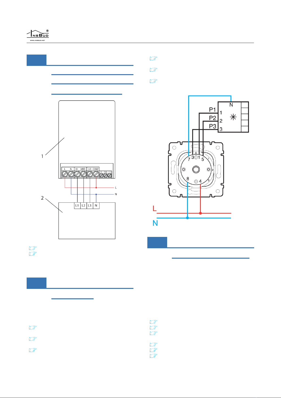
17 Connection - replacement
of LEGRAND
To replace the Legrand SISTENA LIFE switch for
ventilation control 4 positions 0-1-2-3 (part number
775958) switch:
3 from Legrand switch - to HI screw terminal
in controller
5 from Legrand switch - to MED screw termi-
nal in controller
1 from Legrand switch - to LO screw terminal
in controller
4 from Legrand switch - to L screw terminal
in controller
8 from Legrand switch - to N screw terminal
in controller
7 from Legrand switch (if connected) - to N
screw terminal in controller
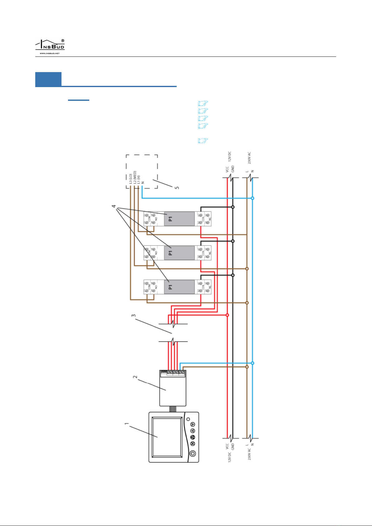
18 Connection - single phase
fan with autotransformer
Below is an example of how to connect a IB–Tron
3100FAN-230V controller with a single-phase fan
using an autotransformer. The example shows the
connection of two fans connected on separate auto-
transformers with full isolation. In addition, there is
a solution that turns o the autotransformer when
the fans are about to be turned o, so that the auto-
transformer does not consume electricity during „idle
state”.
1- main panel
2- connection module
3- 230V AC relay with a TH35 rail mounting
base
4- autotransformer
5- supply fan
6- exhaust fan
12

WWW.INSBUD.NET
19 Connection - low voltage
cable
If there is a low voltage cable between the AHU and
the controller, e.g. if the control signal is a UTP ca-
ble and the control signal is a 230V phase, additional
relays and a 12V power supply have to be used. The
controller still requires a 230V power supply. If 230V
power supply is not available, use a low voltage con-
troller. Below is an example of connection.
1- main panel
2- connection module
3- low voltage cable, e.g. UTP cable
4- 12V DC relay with TH35 rail mounting
base
5- AHU
14

WWW.INSBUD.NET
20 Installation notes
The main panel together with the connection modu-
le is usually installed in a generally accessible room,
e.g. in the living room. The controller is connected
to the AHU with a multi-wire cable.
In addition, one to several push buttons/switches
can be connected in parallel to the connection mo-
dule for remote ventilation level control.
Such buttons will be usually installed in rooms,
which require temporary increase of ventilation le-
vel from time to time, e.g. in a toilet or a kitchen
Additional push buttons should be connected with
a two-wire cable. Ideally, it should also be a twisted
pair of wires, but this is not an absolute requirement.
You can use a telephone cable or a two-wire cable of
the „link” type.
The installation of additional buttons is optional. If
buttons are not to be mounted, leave the button in-
put terminal unconnected.
21 Turning the controller on
To turn the controller on or o, press the P
button.
When the controller is o, the display shows only
the current temperature. All ventilation level out-
puts are deactivated (open circuit). When the con-
troller is o, the clogged lter detection function is
still active.
22 Conguration menu
The conguration menu is used to set the operating
parameters of the controller. To enter the congura-
tion menu:
If the controller is on, turn it o by pressing
the Pbutton.
With the controller o, press and hold the M
button for about 3seconds.
The controller is in the conguration mode. Menu,
setting number, setting label, setting value and unit
are displayed.
To change the value of the setting shown, press
the DOWN or UP button.
To move to the next setting, press the Mbut-
ton. When the last setting is reached, pressing
the Mbutton again returns to the rst setting.
The controller exits the conguration menu after the
set time of inactivity has elapsed or after pressing
either of the buttons: Por FAN. Pressing the FAN
button or the inactivity time expires saves the chan-
ges and exits the conguration menu. Pressing the
Pbutton cancels the changes and exits the congu-
ration menu.
23 Conguration of outputs
For dierent air handling units available on the mar-
ket, particular ventilation levels may be switched on
according to dierent standards. For example, for
many air handling units lack of any signal from the
controller means that the unit is switched on in the
rst ventilation level. For another type, to switch
on the rst ventilation level, it is necessary to give
a signal to the appropriate input. Also, some AHUs
allow the ventilation to be switched o by means of
an attached controller, while others do not.
The IB–Tron 3100FAN-230V controller can con-
trol dierent types of air handling units. The user
has a possibility to choose the proper signal stan-
dard for the air handling unit. This is done by the
CFG parameter in the conguration menu.
6 types of AHUs have been dened, for which the
LO, MED and HI outputs are switched on for par-
ticular ventilation levels as shown in the table:
15

WWW.INSBUD.NET
CFG = 1
O Ventilation level 1 Ventilation level 2 Ventilation level 3
Possible to set from the controller No Yes Yes Yes
Relay output states
LO
N/A
On O O
MED O On O
HI O O On
The above settings means:
it is not possible to switch the AHU o from the controller (it is not possible to set „o” value in the
operating schedule or in the manual mode). Other ventilation levels are available for setting.
if the controller wants to switch on the rst ventilation level of the air handling unit then relays will be
set as follows: LO = On (short circuit to COM1); MED = O (open circuit with COM1); HI = O (open
circuit with COM1).
if the controller wants to switch on the second ventilation level of the air handling unit then relays will
be set as follows: LO = O (open circuit to COM1); MED = On (short circuit with COM1); HI = O
(open circuit with COM1).
if the controller wants to switch on the third ventilation level of the air handling unit then relays will be
set as follows: LO = O (open circuit to COM1); MED = O (open circuit with COM1); HI = On (short
circuit with COM1).
CFG = 2
O Ventilation level 1 Ventilation level 2 Ventilation level 3
Possible to set from the controller No Yes Yes Yes
Relay output states
LO
N/A
O O O
MED O On O
HI O O On
CFG = 3
O Ventilation level 1 Ventilation level 2 Ventilation level 3
Possible to set from the controller Yes Yes Yes Yes
Relay output states
LO On O O O
MED O O On O
HI O O O On
CFG = 4
O Ventilation level 1 Ventilation level 2 Ventilation level 3
Possible to set from the controller Yes Yes Yes Yes
Relay output states
LO O On O O
MED O O On O
HI O O O On
CFG = 5
O Ventilation level 1 Ventilation level 2 Ventilation level 3
Possible to set from the controller Yes Yes Yes Yes
Relay output states
LO O On On On
MED O O On O
HI O O O On
16

WWW.INSBUD.NET
CFG = 6
O Ventilation level 1 Ventilation level 2 Ventilation level 3
Possible to set from the controller Yes Yes Yes Yes
Relay output states
LO O O O On
MED O O On O
HI O On On On
To set the appropriate output signal standard:
Enter the conguration menu. Press the M
button until the setting number 01, labeled
CFG, appears on the display.
Set the value. Exit the conguration menu or
move to another setting.
24 FAN input operation
The user can choose one of the three modes of ope-
rating the additional digital input FAN.Mode 1 and
2 enables the use of a monostable button, mode 3 -
a bistable switch.
1. Ventilation. After short pressing of the additio-
nal button, connected to the FAN input, tem-
porary change of the ventilation level takes place
(temporary ventilation). The user decides which
ventilation level should be switched on at that
moment, as well as the time how long this venti-
lation level is switched on. For example, if the but-
ton is placed in the kitchen, the user can tempo-
rarily set the highest ventilation level by pressing
the button. Another example would be a button
in the bathroom, which allows to temporarily stop
ventilation while taking a bath to raise the tem-
perature in the bathroom. After the ventilation
time has elapsed, the controller will switch back
to the mode the AHU was in before the button
was pressed. To exit the ventilation mode before
the expiry of the set ventilation time, press and
hold the additional button for about 3seconds.
When the ventilation mode is active, the ventila-
tion icon is shown on the control panel.
2. Increasing ventilation level. Each short press
of the button increases the ventilation level. If
the AHU is in the highest ventilation level, pres-
sing the button switches on the lowest ventila-
tion level (for AHU without the possibility to
switch o) or switches o (for AHU with the
possibility to switch o). The sequence is repe-
ated. If the controller operates in manual mode
(MANUAL), pressing an additional button cau-
ses permanent change of ventilation level.If the
controller operates in automatic mode (AUTO),
pressing the additional button causes switching to
semi-automatic mode (OVERRIDE), i.e. venti-
lation level change until the end of the current
time period. To return to automatic mode, press
and hold the additional button for about 3se-
conds.
3. Ventilation level override. This mode allows
connecting a bistable switch to the digital input
FAN. The switch can be placed e.g. near a kit-
chen hood. When this switch is activated (short-
circuited), the programmed ventilation level is
started and it lasts as long as the switch is ac-
tivated. After deactivation of the switch (open-
circuited), ventilation level returns to the mode,
in which it was before the switch was activated.
In this mode when digital input is short-circuited
the ventilation icon is displayed on the screen.
To set FAN input operation:
Enter the conguration menu. Press the M
button until the setting number 02, labeled
INMOD, appears on the display.
Set value 1 to set the ventilation function. Set
value 2 to set increasing ventilation level func-
tion. Set value 3 to set the ventilation level
override. Exit the conguration menu or move
to another setting.
25 Temporary ventilation
level
When an additional digital input FAN has been as-
signed a ventilate function (parameter INMOD =
1) or a ventilation level override function (parameter
INMOD = 3), the user should dene which ventila-
tion level will be activated when the additional but-
17

WWW.INSBUD.NET
ton is pressed in ventilate mode or when the switch
is shorted in ventilation level override mode. To set
the temporary ventilation level:
Enter the conguration menu.Press the M
button until the setting number 03, labeled
b_SPd, appears on the display.
Set the ventilation level that will be started
when the external button is pressed. Exit the
conguration menu or move to another setting.
26 Ventilation time
When an additional digital input FAN has been assi-
gned with ventilation function (parameter INMOD
= 1), the user should dene how long after pressing
additional button ventilation should last. To set the
ventilation time:
Enter the conguration menu. Press the M
button until the setting number 04, labeled
bTIME, appears on the display.
Set the ventilation time in minutes (from 1 to
30). Exit the conguration menu or move to
another setting.
27 Calibration
If the temperature indicated by the controller diers
from the actual temperature, the temperature sensor
should be calibrated. To set the calibration:
Enter the conguration menu. Press the M
button until the setting number 05, labeled
CALIB, appears on the display.
Set the value by which the current tempera-
ture indication should be changed in order to
obtain the correct indication. For example, if
20◦C is displayed and the actual temperatu-
re is 18◦C, set −2◦C. Exit the conguration
menu or move to another setting.
28 Idle time
Idle time is the time after which the controller exits
parameter setting mode to default operating mode,
calculated from the last time any of the buttons were
pressed. A larger value gives the user more time to
enter settings.
To set the idle time:
Enter the conguration menu. Press the M
button until the setting number 06, labeled
PTD, appears on the display.
Set the appropriate value. It can be selected
from the range of 5÷30 s, with a step of 5s.
Exit the conguration menu or move to ano-
ther setting.
29 Backlight time
Backlight time is the time after which the LCD bac-
klight tuns o, calculated from the last time any of
the buttons were pressed. To set the backlight time:
Enter the conguration menu. Press the M
button until the setting number 07, labeled
LIGHT, appears on the display.
Set the appropriate value. It can be selected
from the range of 10 ÷60 s, with a step of 10s.
It can also be set to OFF - backlight always
o or On - backlight always on Exit the con-
guration menu or move to another setting.
30 Backlight intensity
The IB–Tron 3100FAN-230V controller is pro-
grammed to automatically turn o the screen bac-
klight when the backlight time expires. By default,
the backlight is then turned o completely. However
user can set the controller not to turn o the bac-
klight completely, but only to decrease its intensity.
User can also set the backlight intensity when the
controller is active.
To set the intensity of the backlight when the con-
troller is active:
Enter the conguration menu. Press the M
button until the setting number 08, labeled
LT_oN, appears on the display.
Set the intensity of the backlight (in percent)
that will be maintained when the controller is
active. Exit the conguration menu or move to
another setting.
18

WWW.INSBUD.NET
To set the intensity of the backlight when the con-
troller is inactive:
Enter the conguration menu. Press the M
button until the setting number 09, labeled
LT_oFF, appears on the display.
Set the backlight intensity (in percent) that
will be maintained after the backlight timeout
(instead of turning it o completely). Exit the
conguration menu or move to another setting.
31 Temperature unit
The user can choose whether to display the tempe-
rature in degrees Celsius ◦C or Fahrenheit ◦F.
To set the temperature unit:
Enter the conguration menu. Press the M
button until the setting number 10, labeled
UNIT, appears on the display.
Set the temperature unit. Exit the congura-
tion menu or move to another setting.
32 Time format
The user can choose whether to display the time in
12 or 24 hour format. To set the time format:
Enter the conguration menu. Press the M
button until the setting number 11, labeled
CLOCK, appears on the display.
Set 12 or 24 hour format. Exit the congura-
tion menu or move to another setting.
33 Filter change reminder
The user can set a reminder to change the lter. User
need to specify the time after which the control pa-
nel enters the reminder mode. To set the lter change
reminder:
Enter the conguration menu. Press the M
button until the setting number 12, labeled
FILTR, appears on the display.
Set the number of days after which the lter
change reminder is activated or set „OFF” to
disable the reminder. Exit the conguration
menu or move to another setting.
When the time limit expires, repeat the step of
setting the number of days, otherwise the alarm
is still active.
34 Alarm states
The controller can report alarms (e.g. lter change)
both when it is on and when it is o. To set whether
the alarm information is to be displayed also when
the controller is switched o:
Enter the conguration menu. Press the M
button until the setting number 13, labeled
ALoFF, appears on the display.
Set the appropriate setting:
YES - alarms are always reported.
NO - no alarms are reported when the con-
troller is in the o mode.
Exit the conguration menu or move to another set-
ting.
35 Firmware version
To check the rmware version:
Enter the conguration menu. Press the M
button until the setting number 14, labeled
VER, appears on the display.
The manufacturer promotes a policy of development
and therefore reserves the right to make changes to
the controllers and manuals without prior notice.
The manufacturer is open to all kinds of suggestions
that will improve our controllers. If you have an idea
for adding a new feature or need an unusual solution,
please contact us.
This manual is valid for IB–Tron 3100FAN-230V
controller with rmware version 07.
19

WWW.INSBUD.NET
36 Time and day of the week
To set the current time and day of the week:
Turn on the controller.
Press and hold the FAN button for about 3
seconds. The displayed time starts ashing.
Set the current time.
Press the FAN button again. The day of the
week will start ashing.
Set the day of the week:
Mon - Monday.
Tue - Tuesday.
Wed - Wednesday.
Thu - Thursday.
Fri - Friday.
Sat - Saturday.
Sun - Sunday.
Conrm the settings.
37 Factory settings
To reset the controller and return to the factory set-
tings:
Turn o the controller.
Press and hold for about 3 seconds both but-
tons: Mand FAN simultaneously.
The display will show RESET for about 5 se-
conds.
38 Keypad lock
To protect the controller from unwanted changes to
settings, user can lock the keypad.
When the keypad lock is active, the display shows
a padlock symbol and the keypad does not respond
to the pressed keys.
To enable/disable the keypad lock:
Press and hold for about 3 seconds both keys:
DOWN and UP simultaneously.
39 Operating schedule
- AUTO mode
In automatic mode, user can set an operating sche-
dule. It means that the programmed ventilation level
of the AHU is automatically set at certain time.
Thanks to the operating schedule it is possible to set
ventilation level lower in the periods when, for exam-
ple, the building is not used or during the night, and
higher when the building is used.
Four time periods can be programmed for each day
of the week, which are symbolically represented on
the display:
Time period no. 1.
e.g. 7:00 - wake-up call
Time period no. 2.
e.g. 9:00 - leaving home
Time period no. 3.
e.g. 15:00 - returning home
Time period no. 4.
e.g. 21:00 - sleep
To set the operating schedule:
Turn on the controller. Make sure that the
controller is set to automatic mode (time pe-
riods and AUTO symbols are visible on the
display).
If the hand symbol (manual mode) appears on
the display instead of the time periods sym-
bol, press the Mbutton. Pressing this button
when the controller is turned on switches be-
tween manual and automatic mode.
20
Table of contents
Popular Controllers manuals by other brands


Glentronics
Glentronics USC3 installation instructions

YASKAWA
YASKAWA JOHB-GA50 installation manual

Syntec
Syntec S08-SMD-33B Series installation instructions

Johnson Controls
Johnson Controls TC-8902 installation instructions

Vacon
Vacon 100X series Installation and maintenance manual

Skov
Skov DOL 834 Technical manual