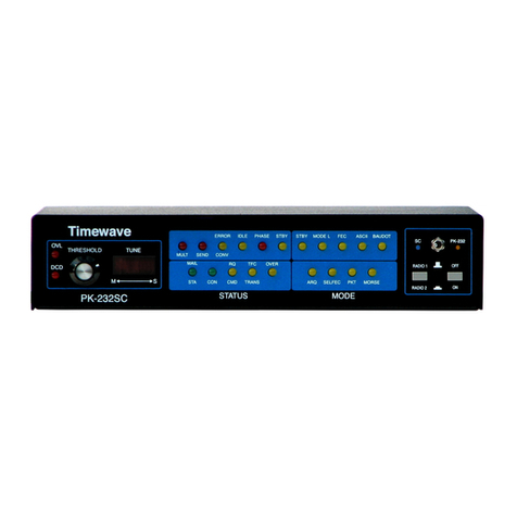
Timewave DSP-232 User manual

DSP-232 Multi-Mode Operating Manual
Welcome
Thank you for purchasing a Timewave product! Before you go any further, please fill out and return the enclosed
Warranty Registration Card. Only a portion of all warranty cards are return, which makes it hard to keep Timewave
customers up to date. From time to time, Timewave offers updates to its products--we can only tell you about these
updates if we have your warranty card on file, so send it in if you haven’t already done so. Returning your warranty
card also places you on Timewave’s catalog mailing list.
FCC Regulations
This device complies with Part 15 of the FCC rules. These rules are designed to provide reasonable protection
against harmful interference in a residential installation. This device generates, uses, and can radiate radio frequency
energy and, if not installed and used in accordance with the instructions, may cause harmful interference to radio
communications. However, these is no guarantee that interference will not occur in particular installation. If this
device does cause harmful interference to radio or television reception, which can be determined by turning the
device on and off, the user is encouraged to try to correct the interference by one or more of the following measures:
• Reorient or relocate the receiving antenna.
• Increase the separation between the device and receiver.
• Connect the device into an outlet on a circuit different from that to which the receiver is connected.
• Consult the dealer or an experienced radio/TV technician for help.
Changes or modifications not expressly approved by the manufacturer will void the user’s authority to operate the
device.
You must use shielded cables for all device connections, then tie all grounding wires/shields to a single point,
normally the radio. You need an effective station ground or you’ll have problems when RFI infiltrates your
equipment and causes all kinds of unexpected problems.
Disclaimer
As part of its continuing program of product improvement, AEA reserves the right to make changes in this
product’s specifications or documentation. AEA also reserves the right to incorporate and issue any information
thus supplied in whatever manner it deems suitable, without incurring any obligation whatsoever.
Copyright
© 1995, 2005 by Timewave Technology Inc. All rights reserved.
Under copyright laws, this manual can not be reproduced in any form without prior written permission from Timewave Technology
Inc. No patent liability is assumed, however, with respect to the use of the
information contained herein.
This manual may contain errors, omissions or “typos.” Please send your comments, suggestions, and corrections to: Timewave
Technology Inc., 1025 Selby Ave, Suite 101, St. Paul, MN 55104
Table of Contents
ii September, 05

DSP-232 Multi-Mode Operating Manual
FCC Regulations ................................................................................................................................ii
Chapter 1 - DSP-232
Capabilities .....................................................................................................................................1-1
What did & didn’t come in the box ..................................................................................................1-2
A Tour of the DSP-232....................................................................................................................1-3
The Front ................................................................................................................................1-3
Mode Indicators ......................................................................................................................1-3
Status Indicators.....................................................................................................................1-5
Other Indicators ......................................................................................................................1-6
The Back.................................................................................................................................1-7
Chapter 2 - Power Supply and Computer Installation
Connecting Power...........................................................................................................................2-1
Turning it On ...................................................................................................................................2-1
Re-Initialization ...............................................................................................................................2-2
Connecting Your Computer to the DSP..........................................................................................2-2
The Cable ...............................................................................................................................2-2
Peripherals and IRQ Conflicts ................................................................................................2-4
The Control Program..............................................................................................................2-4
System Start-up and Loop-back Tests ...........................................................................................2-6
Radio Port 1 Test....................................................................................................................2-6
Radio Port 2 Test....................................................................................................................2-8
Chapter 3 - Radio Installation
Radio Connection Requirements....................................................................................................3-1
Connections for Specific Transceiver Models ................................................................................3-2
Basic Connections and Adjustments..............................................................................................3-2
Connections for Direct FSK on RTTY.....................................................................................3-4
Transceiver Adjustments ................................................................................................................3-4
FM Transceiver Adjustments..................................................................................................3-5
SSB Transceiver Adjustments................................................................................................3-7
Chapter 4 - Terminal Commands
Command Mode .............................................................................................................................4-1
Converse Mode...............................................................................................................................4-1
Transparent Mode...........................................................................................................................4-2
Host Mode.......................................................................................................................................4-2
Kiss Mode .......................................................................................................................................4-2
Parameters and Arguments............................................................................................................4-2
List of General and Terminal Related Commands .........................................................................4-3
Complete DSP-232 Command List.................................................................................................4-29
Chapter 5 - Packet Operation
Switching Between Radio Ports......................................................................................................5-1
Tuning in Packet Stations VHF/UHF ..............................................................................................5-2
What it Means.........................................................................................................................5-5
Who’s Out There?...................................................................................................................5-6
Talking to Yourself..........................................................................................................................5-7
Connecting..............................................................................................................................5-7
CTEXT....................................................................................................................................5-8
Setting Up for Transmitting.............................................................................................................5-8
Calling CQ.......................................................................................................................................5-8
September, 05 iii

DSP-232 Multi-Mode Operating Manual
Going on the Air......................................................................................................................5-9
I’m having Trouble Connecting...............................................................................................5-9
More Packet Features.....................................................................................................................5-10
Nodes and Node Operation....................................................................................................5-10
Your DSP acts as a Node!..............................................................................................................5-10
Operating Your Node..............................................................................................................5-11
Digipeating..............................................................................................................................5-13
Are Your a Digipeater?...........................................................................................................5-13
Identifying as a Digipeater......................................................................................................5-14
Time-stamping Packet Messages ..........................................................................................5-14
Multiple Connection Operation .......................................................................................................5-14
Setting Up...............................................................................................................................5-14
The Channel Switching Character..........................................................................................5-14
CHCALL..................................................................................................................................5-15
HF Packet Operation ......................................................................................................................5-15
Where to Operate...................................................................................................................5-15
Settings...................................................................................................................................5-16
Tuning in HF Packet Stations.................................................................................................5-16
Transmitter Adjustments.........................................................................................................5-16
Going on the air ......................................................................................................................5-16
Packet Meteor Scatter Extension ...................................................................................................5-17
Immediate and Advanced Packet Commands ...............................................................................5-18
Packeting Through Voice Repeaters..............................................................................................5-19
Packet Formatting and Editing........................................................................................................5-19
Packet Protocol Basics...................................................................................................................5-20
Packet Mail......................................................................................................................................5-23
Packet Commands..........................................................................................................................5-23
Chapter 6 - Global Positioning System Applications
Why do GPS in the DSP-232?........................................................................................................6-1
What is APRS? ...............................................................................................................................6-1
Hardware Configurations................................................................................................................6-2
Setting Up the DSP-232 for GPS Operation...................................................................................6-3
Stand Alone Tracking Device Set Up.....................................................................................6-4
Connecting the GPS Receiver to the DSP-232..............................................................6-5
Hardware Single Port Mode....................................................................................................6-5
Dual Port Mode Set Up...........................................................................................................6-6
Building your own APRS cable.......................................................................................................6-6
Schematic Diagram for the APRS Adapter Cable..................................................................6-7
DSP-232/ULTIMETER II Stand Alone Weather Set Up .................................................................6-7
GPS Specific Commands ...............................................................................................................6-8
Chapter 7 - MailDrop Operation
MailDrop Memory............................................................................................................................7-1
Expanding Your MailDrop...............................................................................................................7-2
Setting Up Your MailDrop...............................................................................................................7-2
Accessing and Commanding Your MailDrop..................................................................................7-2
Monitoring Your MailDrop...............................................................................................................7-3
Packet MailDrop Prompts and Operation.......................................................................................7-3
Packet MailDrop command summary.....................................................................................7-3
Sending Mail ...................................................................................................................................7-5
Sending Other Types of Messages........................................................................................7-6
Message Numbers..................................................................................................................7-9
Forwarding and Reverse-Forwarding.....................................................................................7-9
Settings for Auto-forwarding...................................................................................................7-9
Entering a Message for Reverse Forwarding.........................................................................7-9
AMTOR MailDrop............................................................................................................................7-10
iv September, 05

DSP-232 Multi-Mode Operating Manual
Command Definitions for AMTOR..........................................................................................7-11
PACTOR MailDrop..........................................................................................................................7-12
Command Definitions for PACTOR........................................................................................7-12
MailDrop Commands......................................................................................................................7-13
Chapter 8 - ASCII and BAUDOT Operation
Setting Up for ASCII........................................................................................................................8-1
Setting Up for BAUSDOT................................................................................................................8-2
Receiving ASCII & BAUDOT ..........................................................................................................8-2
Going on the Air..............................................................................................................................8-3
Calling CQ.......................................................................................................................................8-3
Answering a CQ..............................................................................................................................8-4
The QSO ........................................................................................................................................8-4
Roundtable QSOs and Nets...........................................................................................................8-4
Operating Tips and Options............................................................................................................8-5
BAUDOT and ASCII Commands....................................................................................................8-7
Chapter 9 - AMTOR Operation
Setting Up .......................................................................................................................................9-2
Receiving AMTOR..........................................................................................................................9-2
Going on the Air..............................................................................................................................9-3
Calling CQ...............................................................................................................................9-4
Answering Another Station’s CQ............................................................................................9-4
Beginning a QSO....................................................................................................................9-4
Ending a QSO.........................................................................................................................9-4
Seizing the Link ......................................................................................................................9-5
Killing the Link.........................................................................................................................9-5
Roundtable QSOs...........................................................................................................................9-5
“Hidden” QSOs ...............................................................................................................................9-5
Operating Tips and Options............................................................................................................9-6
MailDrop Operation.........................................................................................................................9-7
LED Status and Mode Indicators....................................................................................................9-8
AMTOR Commands........................................................................................................................9-10
Chapter 10 - Morse Operation
Special Morse Characters ..............................................................................................................10-1
Setting Up .......................................................................................................................................10-1
Tuning in Morse Stations................................................................................................................10-2
Going on the Air..............................................................................................................................10-2
Calling CQ...............................................................................................................................10-2
Operating Tips ................................................................................................................................10-3
Type Ahead Buffer..................................................................................................................10-3
Operating QSK........................................................................................................................10-3
Morse Commands...........................................................................................................................10-4
Chapter 11 - SIAM and NAVTEX Operation
Setting Up for SIAM........................................................................................................................11-1
Reception........................................................................................................................................11-2
Copying Encoded RTTY Transmissions.........................................................................................11-2
About NAVTEX ...............................................................................................................................11-3
Setting Up for NAVTEX...................................................................................................................11-3
Receiving NAVTEX Signals............................................................................................................11-3
SIAM and NAVTEX Commands .....................................................................................................11-4
Chapter 12 - PACTOR Operation
Setting Up .......................................................................................................................................12-2
September, 05 v

DSP-232 Multi-Mode Operating Manual
Receiving PACTOR........................................................................................................................12-2
Going on the Air..............................................................................................................................12-3
Roundtable QSOs...........................................................................................................................12-4
Calling CQ...............................................................................................................................12-4
Answering Another Station’s CQ............................................................................................12-4
Beginning a QSO....................................................................................................................12-4
Ending a QSO.........................................................................................................................12-5
Killing the Link.........................................................................................................................12-5
Seizing the Link ......................................................................................................................12-5
File Transfers..................................................................................................................................12-5
MailDrop Operation.........................................................................................................................12-5
Operating Tips and Options............................................................................................................12-6
Status and Mode Indicators............................................................................................................12-7
PACTOR Commands ....................................................................................................................12-8
Chapter 13 - Troubleshooting
A Troubleshooting Primer...............................................................................................................13-1
Power Supply..........................................................................................................................13-2
Power Supply Cable...............................................................................................................13-2
The DSP-232..........................................................................................................................13-2
Cable from the DSP-232 to Computer....................................................................................13-2
Computer/Software.................................................................................................................13-2
Cable from DSP-232 to Radio................................................................................................13-2
Radio.......................................................................................................................................13-3
General Error Messages.................................................................................................................13-4
Packet Error Messages ..................................................................................................................13-5
MailDrop Error Messages...............................................................................................................13-7
DSP-232 Status and Error Messages.............................................................................................13-7
Out of the Box Problems.................................................................................................................13-9
Computer to DSP-232 Problems....................................................................................................13-9
Radio to DSP-232 Problems...........................................................................................................13-10
Morse Problems..............................................................................................................................13-10
ASCII/BAUDOT Problems ..............................................................................................................13-11
SIAM Problems...............................................................................................................................13-12
MailDrop Problems .........................................................................................................................13-13
Packet Problems.............................................................................................................................13-14
AMTOR & PACTOR Problems .......................................................................................................13-17
DSP-232 Problems.........................................................................................................................13-19
Index
Appendix A - Specific Radio Connections
Radio Connection Notes.................................................................................................................A-1
Radio ListA-2
Radio Connection Figures..............................................................................................................A-6
Appendix B - Specifications
Appendix C - Limited Warranty
Appendix D - 256K RAM upgrade
Appendix E - Schematics and Pictorial
vi September, 05

Chapter 1 The DSP-232
Chapter 1
The DSP-232
Overview
The DSP-232 was designed by Timewave Technology Inc. to be the ultimate digital operating platform
when coupled to your computer or “dumb” terminal. The DSP couples your HF, VHF, UHF transceiver(s) or short-
wave receiver to your computer so you can “talk” to other Amateurs or listen in to their—or a utility station’s—
digital and Morse communications. This unit is state-of-the-art and has been designed with an eye toward the future.
The architecture and parts used in the DSP-232 allow room for future technological enhancements. Timewaves’s PK-
232MBX left a decade long legacy of dependability and high-performance digital communication, the DSP-232 will
carry you through the next decade, and well into the next century.
Capabilities
With the DSP you can transmit and receive all the popular amateur digital modes. You can receive other modes
such as NAVTEX and bit-inverted Baudot RTTY. These capabilities, along with SIAM (Signal Identification and
Acquisition Mode), make the DSP ideal for the digital signal short-wave listeners (SWL) as well as the active
digital communication users. New modes will become popular and you can be assured this unit will be able to
handle them.
The DSP will transceive in the following modes:
♦AX.25 packet on HF (300 bps), VHF and UHF (9600 bps and 1200 bps)
♦Baudot and ASCII RTTY
♦AMTOR/SITOR CCIR Rec. 476 and 625
♦Morse Code
♦PACTOR
In addition, the DSP receives the following modes:
♦NAVTEX marine broadcasts and AMTEX amateur bulletins
♦Bit-inverted Baudot RTTY
The DSP also has the following special features:
♦Gateway firmware which allows the DSP-232 to operate as a node and identify TCP/IP, TheNet, and
NET/ROM stations. There are two heard lists with Gateway, one for nodes heard and one for stations heard.
♦Memory ARQ for better HF throughput in marginal conditions.
DSP-232 features continued. . .
September, 05 1-1

Chapter 1 The DSP-232
♦Numerous external adjustments, ports, and connectors.
♦The ultimate in digital filtering with the high-power, high-speed Digital Signal Processor.
♦The unique LED display which keeps you informed of system activity. This display allows for future modes
and features as no other display can. After all, we designed this unit for growth.
♦Packet/AMTOR/PACTOR MailDrop message handling.
♦A Mailbox that can expanded to 242K (256K RAM).
♦KISS mode for TCP/IP packet applications.
♦Host mode for popular Host application programs.
What Did—and Didn’t—Come In the Box
Besides this manual, the following items are enclosed:
♦two 5-pin DIN radio cable
♦one 8-pin DIN connector
♦two RX audio cables
♦one 2.1mm power cable
♦one wire loop-back jumper
♦an RS-232 serial cable with DB-9 connectors (pins 1-3 and 5-8 connected)
Here’s what isn’t enclosed:
♦DOS, MacIntosh, or other computer platform software to operate your DSP
♦microphone connectors for your radio(s)
♦a power supply
♦a computer and a radio!
The DSP will work with practically any telephone modem or terminal emulation program that your computer can run
as long as it uses the full ASCII character set. However, PK-Term for Windows is powerful
programs offered by CSS that istailor-made for its controller products. These programs offer many operating and
utility features—and conveniences—that simply aren’t found in typical modem and 3rd party controller programs.
But, if you do run Windows, PK-Term for Windows is the best amateur radio
has to offer in Windows control software. Visit http;//www.cssincorp.com
for more details about PK-Term programs.
We also didn’t enclose any mike connectors because we don’t know which brand or model of radio you plan to use
with your DSP.
Finally, we didn’t include a power supply since many owners simply connect their DSP to the same 12 VDC supply
that powers their radio and station accessories. If you want to operate your DSP from a “power cube” that plugs into
your wall outlet, you can purchase one locally or you can purchase the AC-5power supply from Timewave
or through your favorite electronic equipment dealer.
Your Radio...
We presume that you have an operating radio transceiver or short-wave receiver that you’ll use with your DSP. In
the Amateur bands, most of the VHF packet activity occurs on the 2-meter FM band while most of the HF digital
activity occurs on the 20-meter band. By convention, an HF receiver or transceiver must be capable of SSB
operation in order to communicate digitally to other stations. While no specific brand of transceiver is required, we
recommend that a modern transceiver (built in the last 20 years) be used. Specific transceiver connections are
described in Appendix A of this manual.
1-2 September, 05

Chapter 1 The DSP-232
Most modern radio transceivers are capable of excellent performance in Morse, Baudot and ASCII RTTY,
AMTOR, PACTOR, and packet radio. Although AMTOR Mode A (ARQ) and PACTOR operation imposes more
demanding switching speed requirements than the other operating modes, most radios will operate in both AMTOR
and PACTOR modes without any modifications. (See the AMTOR operating section for further details on timing
requirements.) The DSP has software-controlled timing variations that permits operation with nearly all the HF,
VHF and UHF radios in general use today.
...and Computer
You’ll need a computer or “dumb” terminal that has an RS-232 serial communications port in order to have it
communicate with your DSP. The most popular computers are IBM™-PC compatibles, PC laptops, and Apple
Macintosh™ (and Powerbooks™).
For the sake of brevity in this manual, instead of using both the phrases “dumb terminal” and “computer”
interchangeably we’ll just use the word, computer.
A Tour of the DSP-232
Before you leap ahead into the next chapter to see how to hook up your DSP, you should read this section to find
out what all those LEDs, adjustment levels and connectors are on the unit and what they do. If their functions or
terms sound cryptic to you now, don’t worry about it—they’ll be explained fully in later chapters.
Carefully remove the DSP from its box and plastic bag and inspect the it for signs of damage that may have
occurred during shipment. If there’s visible damage, please contact the dealer or shipper. Don’t install or use a
damaged controller.
The Front
Front view of the DSP-232
Now, set it on the table or hold it in your hands and take a few minutes here to take a guided tour of your controller,
starting with the blacked-out display on the left-hand side of the front of the DSP labeled Mode and Status. Under
this black display are two, seven-segment LED indicators. These lights tell you which mode you’re using and
what’s going on while you’re in that mode. Let’s start with the ones in the MODE box.
Mode Indicators
In the Mode area, there are twelve possible symbols that can appear. Below is a rundown of these symbols. You will
find a legend on the front of the DSP-232 which tells you what symbols stand for what mode.
‘P’ will light when you’re using VHF/UHF or HF Packet at 9600, 1200, or 300 bps.
‘A’ will light when you’re in the AMTOR mode.
September, 05 1-3

Chapter 1 The DSP-232
‘C’ will light when you’re using the DSP to decode Morse code signals.
‘b’ will light when you’re in the Baudot mode.
‘E’ will light when you’re in the ASCII mode.
‘S’ will light when you’re using Signal Identification and Acquisition mode (SIAM™) to
identify signals.
‘d’ doesn’t stand for an actual mode, but will light during special telemetry and data
conversion applications.
‘n’ will light when you’re copying NAVTEX data.
‘L’ will light when calibrating the DSP.
‘r’ will light when you’re working PACTOR.
‘II’ is an optional symbol which will be used for future applications.
‘F’ is an optional symbol which will be used for future applications.
Status Indicators
Now, let’s move on to the Status Indicators. There are ten symbols which may appear in the Status area. Below is
an explanation of these symbols. The legend on the front of the DSP-232 tells you what the symbols mean as well.
1-4 September, 05

Chapter 1 The DSP-232
‘F’ lights when you’re in FEC mode in AMTOR or PACTOR.
‘A’ comes on when you’re in ARQ mode in AMTOR.
‘L’ comes on when you’re in Listen mode in AMTOR or PACTOR
‘t’ comes on when sending “traffic” in AMTOR.
‘E’ This stands for ERROR. When not in packet, it’ll glow when it has trouble receiving—
or when it has received—a bad “block” of data while in PACTOR or AMTOR .
‘P’ Stands for PHASE and indicates that while in AMTOR or PACTOR, your transmitter is
trying to lock onto and synchronize with another station’s signal.
‘S’ Stands for SELFEC and will glow when you’re operating SELFEC AMTOR.
‘I’ IDLE is next. When on—while in AMTOR or PACTOR—it indicates that although
you’re connected to another station, no traffic is being transmitted or received.
‘r’ comes on when an error has occurred and the DSP ‘Requests’ a re-transmission.
‘o’ Stands for OVER and lights up when the DSP goes from transmit to receive while in
AMTOR or PACTOR.
Other Indicators
September, 05 1-5

Chapter 1 The DSP-232
To the left of the Mode LCD display is ‘MAX’. This is the abbreviation for Maximum
Throughput. This will light when PACTOR data is being throughput as fast as the mode
allows. When in PACTOR, with the ‘P’ showing in the Mode area, you will be able to
distinguish the top line of the ‘P’ from this slash because the ‘MAX’ slash will blink.
Also on the left is ‘CMPS.’ This is the abbreviation for Compression. This will light when
data is compressed in PACTOR.
There are three abbreviations to the left of the STATUS portion of the window: CON, STA, and MULT.
CON is the abbreviation for CONnected, and glows while you’re connected to another
station while in packet.
STA is the abbreviation for STAtus, and glows while in packet when you’ve sent a packet
that hasn’t been acknowledged (acked) by another station, yet.
MULT is the abbreviation for MULTiple. It glows constantly while you’re chatting
(connected) with more than one station at a given time while in packet. When the MULT
light blinks, it means that the DSP’s memory (32K standard, expandable to 256K) buffer is
full.
Note: the buffer can be filled with or without the computer connected to the controller since the DSP’s buffer
stores whatever it hears from the radio—not just the computer.
At the bottom of seven-segment LCD displays are two dots labeled: TX and MAIL.
TX stands for Transmit. This LCD dot will glow when you are transmitting data in any
mode.
Mail stands for Mailbox. This LCD dot will blink when you have mail waiting for you in
your mailbox.
Moving to the right is the tuning indicator. When you tune a signal, the LEDs behind the tune window will light a
certain way to tell you whether you’re tuned above or below the frequency of the signal you’re trying to receive.
The ‘Mark’ and ‘Space’ above the TUNE window denotes which way the Mark and Space tones are. With the
LEDs glowing, you’ll refer to the Mark and Space to see if the tones are above or below frequency.
Next is DCD, which means Data Carrier Detect. In HF, whenever your DSP hears anything—be it noise or someone
else’s signal—the LED will glow providing that the threshold is adjusted correctly. If it doesn’t glow, then it means
that the DSP can’t ‘hear’ any signals. In 1200 and 9600bps VHF packet, the light only glows if a valid packet signal
is heard.
1-6 September, 05

Chapter 1 The DSP-232
Just to the right is OVL, which means Overload. When the DSP’s threshold is too high, the Overload LED will
glow. Too much volume will allow an excessive amount of noise into the DSP. If this occurs, turn the volume on
the receiver down.
The last LED on the right is the ON indicator. When this LED is glowing, your DSP is being supplied with power.
To the right is the ON/OFF power switch. With it in, the DSP powers up; out, it’s off.
The Back
Rear view of the DSP-232
Turn the DSP around so you can see the back. AEA feels that the back of the unit is just as important as the front.
The attention to the back of the unit makes the DSP compatible with the equipment you have now, the equipment
you will buy in the future, offers convenient adjusting, and provides upgradability for future applications.
Starting from the left again and moving to the right is the station ground stud. This convenient stud provides a
ground for the equipment in your station.
Next is the 12 VDC POWER receptacle. The center pin is (+) and the ring, or outside, is (−).
Moving to the right are three transmit level adjustments. One for 9600 bps on radio port two, one for radio port one,
and one for radio port two.
RX AUDIO 1 is where the audio output from your receiver or transceiver will go if you don’t (or can’t) use Pin 1 of
the RADIO 1 connector. Use this jack if you have a short-wave receiver or just want to listen with your transceiver.
RX AUDIO 2 has the same function as RX AUDIO 1, but for RADIO 2 port.
The RADIO 1 connector is where you’ll plug in the radio transceiver you plan to designate as Radio 1. (Pins 1 and
5’s locations in that jack are marked under the connector.)
The RADIO 2 connector is where you’ll plug in the radio transceiver you plan to designate as Radio 2. (This is an
eight Pin DIN, equipped to accommodate 9600 bps applications.)
AUX/FSK is used when you want to hook up auxiliary equipment to the controller or want to use FSK (Frequency
Shift Keying) with your HF radio’s accessory port—if it has one.
The RS-232 I/O receptacle is where you’ll plug in the cable that connects to your computer.
Finally, the there is the RESET button which allows you to perform a hard reset on the DSP-232.
This ends your tour of the DSP. Let’s move on to the next chapter to hook up your computer and radio.
September, 05 1-7

Chapter 2 Power Supply and Computer Installation
Chapter 2
Power Supply and
Computer Installation
Overview
In this chapter, you’ll power up the DSP and connect it to the RS-232 serial port of your computer. After the
connection has been made, you’ll perform a quick check of the DSP’s internal firmware. You’ll also check the
DSP’s internal modem by performing the all-important “loop-back” test. When you’ve completed this chapter,
you’ll be ready to connect the DSP to your receiver or transceiver and begin using it on the air.
Connecting Power
Before you hook up to your computer, you need to connect power to your DSP. To prevent any potential accidents,
make sure your power supply is off and unplugged before connecting the DSP to a live power source.
(If you have a ready-made power supply, like AEA’s AC-4, insert the coaxial connector into the DSP’s POWER
receptacle, plug the “power cube” into the wall, skip this rest of the section and go to the Turning it On section
below. DO NOT CONNECT YOUR COMPUTER YET.)
Locate the power cable in the accessory bag—the one that’s black but has a white strip running down the length of
one of its conductors—and strip off just enough insulation from the ends of both conductors to connect it to your
12-14 VDC regulated power supply.
!VERY IMPORTANT: your power supply must provide at least 12 VDC @ 1A under load to the DSP for it to
operate correctly.
Fasten the positive (+) lead—the one which has the white stripe running down its length—to the (+) terminal of
your power supply. Connect the other conductor to the negative (−) terminal of your power supply. Insert the
coaxial power plug into the POWER receptacle on the left rear of the DSP. DO NOT CONNECT YOUR
COMPUTER YET.
Turning it On
With the power connections made, turn on your power supply (or plug in the power cube into the wall outlet) then
depress the POWER switch on the front of the DSP. WATCH CLOSELY FOR THE FOLLOWING: the power
LED to glow, the ‘AU’ (AU stands for Autobaud) to light in the 7-segment Mode and Status windows, and the tune
bar LEDs to become active. If this occurs, then switch off the DSP and move on to the section, Connecting Your
Computer to the DSP. If the above doesn’t happen, then go to Chapter 13 - Troubleshooting.
Note: If something other than ‘AU’ glows, the controller probably has been previously initialized and
should be reinitialized as described below.
Re-Initialization
September, 05 2-1

Chapter 2 Power Supply and Computer Installation
If the DSP has been previously initialized, it’s ready to communicate with a computer or terminal at a specific baud
rate (probably 300, 1200, 2400, 4800, 9600 or 19,200bits/sec) or was shut off in the last mode it was operating in,
like packet or Morse. Reinitializing the controller will make it “forget” all of its user-defined parameters and
will return it to its factory default settings. However, by reinitializing it now you’ll have an easier time getting it
up and running later.
To re-initialize the DSP:
1. Turn power off (power button out.)
2. Press and hold the RESET button on the back panel of the DSP.
3. Continue holding the RESET button and turn the DSP on (power button in.)
4. Continue holding the reset button in for five seconds to insure that the controller’s memory has forgotten
all of its previously set parameters.
5. Release the reset button and the unit has been re-initialized.
If the above procedure didn’t restore the proper start-up operation of the DSP’s front panel LEDs, then refer to
Chapter 13 - Troubleshooting.
Connecting Your Computer to the DSP
Make sure that the DSP and computer are turned off before proceeding.
The Cable
For communication to take place between your computer and the DSP, you need a properly wired, shielded cable
that’ll connect the computer’s serial port to the RS-232 I/O port on the back of the DSP. (The cable that
accompanies your DSP is pinned correctly and is ready to use.)
The style of connector you have on your computer is probably a DB-25F (25-pin), a DB-9 (9-pin), or a mini Din-8
for Apple computers (8-pin).
Here’s a table of pin assignments to wire the DSP’s RS-232 I/O port to a typical computer’s serial port see diagram
on next page:
from Apple
DSP-232 to... mini-
RS-232 I/O DB-25F DB-9 DIN-8P Function
1 8 1 2 (DCD)
2 3 2 5 (RxD)
3 2 3 3 (TxD)
5 7 5 4+8 (GROUND)
6 6 6 (DSR)
7 4 7 (RTS)
8 5 8 (CTS)
2-2 September, 05

Chapter 2 Power Supply and Computer Installation
Don’t use a “null modem” cable. This type of cable flips pins 2 & 3 so that pin 2 on one end of the cable is
connected to pin 3 on the other end (and vice versa.) Use a cable that has “straight through” connections like the
ones used to connect computers to a telephone modem since as far as your computer’s concerned, the DSP is a
modem.
Once you’ve tested the cable to make sure it’s pinned correctly, plug one end into your computer’s serial port and
the other end to the RS-232 I/O port on the back of the DSP, then proceed to the System Start-up and Loopback Test
later in this chapter.
Note: The enclosed computer cable was designed to connect directly to a 9-pin, IBM-PC/XT/AT
compatible computer’s RS-232 port. Some less-common machines are listed below.
Apple Computers
If you own an Apple Macintosh or Powerbook-type computer, simply purchase a standard mini-DIN8 to DB-9
modem cable.
Dumb Terminals
If you have an RS-232 “dumb” computer terminal, you may need to change the gender of the cable provided with
your DSP. This can be done with an inexpensive double-male RS-232 gender changing adapter available from
Radio Shack (part number 26-1388, Radio Shack Port Adapter) as well as other computer dealers.
The Computer
If the type of computer you plan to use with the DSP wasn’t mentioned earlier in this chapter, you may find
specific connection information below. You’ll also need a communications program to use with your computer. See
The Control Program section below for information regarding communication programs for many of the above
machines.
Many computers require a serial port adapter card that incorporates the necessary RS-232-C interface circuitry; The
IBM-PC is a good example of this. Computers that don’t have a serial port or permit use of a suitable adapter or
level converter can’t be used with the DSP.
Other Computers with RS-232 Ports
If your computer has an RS-232 port, consult your computer manuals to see which pins are used for TxD, RxD and
signal ground. Read the manufacturer’s recommendations for connecting the serial port to a telephone-type modem
and connect your DSP the same way.
The DSP-232 is configured as Data Communications Equipment (DCE)—it transmits data on pin-2. Most
computers and terminals are configured as Data Terminal Equipment (DTE) transmitting data on pin-3.
If your computer is configured as Data Terminal Equipment (DTE), use the supplied RS-232 cable with a gender
changing adapter, if necessary. These are available from Radio Shack (part number 26-1388) and other computer
stores.
September, 05 2-3

Chapter 2 Power Supply and Computer Installation
Other Computers with Non-Standard Serial Ports
Computers with non-standard serial ports must meet the following conditions:
♦The signal levels must be compatible with RS-232-C. The DSP requires the voltage levels from the computer
be greater than +3 volts in the “asserted” state and 0 volts or less in the “non-asserted” state.
♦The signal polarity must conform to the RS-232-C standard. The 0 or negative-voltage state must correspond
to logical “1” and the positive-voltage state to logical “0.”
♦The computer must be able to correctly receive a signal that meets asynchronous RS-232-C specifications.
The DSP supplies signals that meet this specification.
Make or buy a cable that provides the following connections:
♦The computer’s serial port signal ground or common pin must be connected to the DSP’s serial port
connector, pin 5.
♦The pin on which the computer SENDS data (TxD) must be connected to the DSP’s RS-232 connector, pin 3.
♦The pin on which the computer RECEIVES data (RxD) must be connected to the DSP’s RS-232 connector,
pin 2.
If your computer requires any other signals, you must arrange to provide them. The DSP has the standard hardware
handshake lines available. As a default, the DSP provides XON/XOFF software flow control to the computer or
terminal. The command, XFLOW, can be turned off, disabling software flow control and enabling hardware
handshake if your computer requires it. Hardware flow control is achieved with RTS/CTS (pins 7 and 8) of the DB-
9 RS-232 I/O connector. The documentation provided with your computer or serial card should clarify any special
requirements.
Peripherals and IRQ Conflicts in IBM-PC Compatibles
On a different note, you need to survey your computer system to see what peripherals are connected to it, both
internally and externally. This is important since you can’t connect the DSP to a COM port that’s shared or
occupied by another device like a modem, fax, or mouse card. For example, you may not be able to connect your
DSP to COM 1 if COM 3 is occupied by another device; the same holds true with COM 2 and COM 4. COM ports
are usually paired, meaning COM 1 “sees” what’s connected to COM 3, and COM 2 sees what’s connected to COM
4.
The reason why you have to be careful with COM port pairs is due to something called an Interrupt ReQuest (IRQ)
conflict—devices and peripherals send a distinct set of signals back to the CPU to interrupt its operation when the
device needs “attention.” When two devices have the same IRQ codes, their signals fight for the CPU’s attention
and cause all kinds of trouble. Therefore, if COM 1 or COM 3 are occupied, connect the DSP-232 to COM 2 or
COM 4 if you can. If you can’t, you’ll have to change the hardware (and software) to another IRQ so the shared
devices can “live together” on the paired port. Changing the device’s IRQ from 3 to 5 usually works. (Refer to the
device’s manual for changing its IRQ setting.)
Along the same lines as conflicts, sometimes a TSR (Terminate and Stay Resident) program can cause a
communication problem between the DSP and your computer. Therefore, when setting up your controller for the
first time, disable all of your TSRs to eliminate any potential start-up problems. An easy way to do this is to create a
system disk on “floppy” (in DOS, type FORMAT A: /Sto create a system disk), start-up your computer from that,
then access the communications program you plan to use with your controller.
To prevent programs from automatically booting in your Macintosh or Powerbook, simply hold down the (SHIFT)
key on power-up until you see the Welcome to Macintosh , Extensions Off message.
The Control Program
If you are going to use the PC PakRatt for Windows program supplied with your DSP-232, you will follow the
instructions in the PC PakRatt for Windows manual to install the software on your computer. If you’ll be using your
DSP with a dumb terminal, you won’t need any software and can skip to the next section, System Start-up and
Loop-back Test.
2-4 September, 05

Chapter 2 Power Supply and Computer Installation
The DSP operates in much the same manner as a telephone modem so most telephone modem terminal programs
will work with your DSP. Some of these programs are in “Public Domain” which means they’re free. Other terminal
programs are “shareware” which means you may get them from a friend and try them before you buy them.
Follow the installation directions that come with the terminal program you plan to use. Once installed on your
computer, you should start the program and set its parameters to:
♦Data Rate = 1200 bits per second (Baud)
♦Data bits/word length = 7
♦Parity = EVEN
♦Stop bits = 1
♦Duplex = FULL
♦Handshake = XON/OFF
Note: Early version of PC PakRatt for Windows 2.0 do not list the DSP-232 in the TNC menu. To operate
your DSP-232, you will select the DSP-1232 from the TNC menu. To PC PakRatt for Windows, your
DSP-232 ‘looks’ just like a DSP-1232. Later versions of PC PakRatt for Windows have the DSP-232 listed
in the TNC menu. THIS IS THE ONLY DIFFERENCE BETWEEN EARLY AND LATE RELEASES
OF PC PAKRATT FOR WINDOWS version 2.0.
Note: as a default, the DSP provides XON/XOFF software flow-control to the computer or terminal. The
DSP command, XFLOW, can be turned OFF to disable software flow control and enable hardware
handshake if your computer requires it. Hardware flow control is achieved with RTS/CTS (pins 7 and 8)
of the DB-9 RS-232 I/O connector.
IBM PCs and Compatibles
Although you can use almost any terminal program with your IBM-PC or compatible computer, AEA currently sells
PC-Pakratt-II for DOS and PC-Pakratt for Windows; programs which provide many features not available in
telephone modem programs. (Call AEA’s 24-hour Literature Request line at 800-432-8873 and leave a message.)
Of course, you already own PC PakRatt for Windows.
If you already have one of AEA’s PakRatt programs, follow the instructions in the program’s manual to install the
software on your computer. For initial checkout of the DSP, use the programs’ Dumb Terminal mode.
A partial list of PC programs tested with the DSP includes: PROCOMM Plus, LANLINK, PC PakRatt for Windows
2.0 and 1.0, PC PakRatt II for DOS, YAPP, and the terminal program included with Microsoft Windows 3.1.
Apple Macintosh and Powerbooks
Although you can use almost any Macintosh-based terminal program with your Macintosh or Powerbook, AEA
presently sells the MacRATT program which provides many features not available in telephone modem-type
programs. Again, call or write AEA for more information.
If you already have MacRATT, follow the program’s manual to install the software on your computer. For initial
checkout of the DSP, use MacRATT’s Dumb Terminal mode.
As we mentioned above, an AEA program is not required to use the DSP with your Macintosh or Powerbook. A
partial list of Macintosh programs tested with the DSP includes: MAC TERMINAL, RED RYDER,
MICROPHONE II, SMARTCOMM II and MOCK TERMINAL.
System Start-up and Loop-back Tests
Make sure that you’ve connected your DSP to an adequate power supply and to the RS-232 port of your computer
or terminal.
Radio Port 1 Test
September, 05 2-5

Chapter 2 Power Supply and Computer Installation
1. Don’t connect any cables to your radio yet!
2. If a loop-back jumper is included with your shipment of the DSP-232, plug one end into the 1 hole (TX)
and the other end into the 4 hole (RX) of Radio 1 port on the back of the DSP-232, and go to step 7. If you
did not receive a loop-back jumper, continue following the steps.
Insert Loop-back jumper in holes 1 and 4
3. Remove one of the 5-wire, shielded radio cables from the DSP accessory bag. If you have a single 10-Ft.
cable with 5-pin connectors on each end, cut the cable to the length you need to reach your primary radio.
4. With your pocket knife or wire strippers, remove about an inch (2.5 cm) of cable jacket exposing the five
colored wires and the shield-wire, being careful not to accidentally nick the wires’ insulation.
5. Strip about 1/4 inch (7 mm) of insulation from the green and white wires and short them together by
twisting gently twisting their ends together.
6. Plug the cable into the 5-pin RADIO-1 socket on the DSP’s rear panel. Make sure that the cable at the
connector end faces downward as it leads away from the controller.
7. Set the RADIO 1 AFSK LEVEL pot on the rear of the DSP to 50% rotation (straight up and down) using a
small screwdriver.
8. Turn on your computer. Load and run your communications program. (Choose the TTY option, if
available.)
If you’re using an AEA program, follow its manual’s instructions to enter the packet mode, then skip to Step 11.
Note: Early version of PC PakRatt for Windows 2.0 do not list the DSP-232 in the TNC menu. To operate
your DSP-232, you will select the DSP-1232 from the TNC menu. To PC PakRatt for Windows, your
DSP-232 ‘looks’ just like a DSP-1232. Later versions of PC PakRatt for Windows have the DSP-232 listed
in the TNC menu. THIS IS THE ONLY DIFFERENCE BETWEEN EARLY AND LATE RELEASES
OF PC PAKRATT FOR WINDOWS version 2.0.
Note: You may use a wide range of terminal baud rates with the DSP, but we recommend 1200 baud now
to keep this procedure easy and consistent.
9. Press the DSP’s power switch to the ON position.
The seven segment LCD symbols ‘AU’ (AU stands for Auto Buad) will light. (If the
above doesn’t happen, then refer to Chapter 13 - Troubleshooting.
If your serial port is operating at 1200 baud (this is the terminal baud rate), 7-bit even parity as recommended, you’ll
see the following message:
Please type a star (*)for autobaud routine.
If your serial port is operating at 2400, 4800, 9600, or 19,200 baud (this is terminal baud), you may see some
“garbage” characters. This is normal and you should proceed with Step 10.
2-6 September, 05

Chapter 2 Power Supply and Computer Installation
10. Type an asterisk (*). When the DSP has recognized your computer’s data rate, its ‘AU’ lights will glow as
in the picture above. Your screen will then display the following sign-on message:
AEA DSP-232 Data Controller
Copyright (C)1995 by
Advanced Electronic Applications, Inc.
Release DD.MMM.YY
cmd:
”cmd:” is the DSP’s system prompt. When you enter (or have entered) a command, you’ll see this prompt.
Important: When you enter a parameter or command, type it after the prompt, press the (SPACE)bar once, enter
the command’s “argument” (the variable or text you’re changing)if appropriate, then press (RETURN).
At this point the DSP-232 is in its default mode: 1200 bps VHF Packet.
11. Set the DSP to RADIO PORT 1by typing RADIO 1 (or RAD 1) at the cmd:like this:
RAD 1
11. Enter the following text after the cmd: prompt to set your test callsign to AAA:
MYCALL AAA
After you’ve entered this, the DSP will print the following on the screen:
MYcall was DSP232
MYcall now AAA
12. Enter the following command to “connect” to AAA: (the DSP-232 recognizes the letter Cto mean “connect
to...”)
C AAA
After a few moments, your monitor should display:
*** CONNECTED to AAA
13. Type Hi, there!, then press (RETURN). Your monitor should echo the same message.
If you’ve gotten this far, then the DSP and its VHF packet modem is working properly. If you’re having difficulties,
see Chapter 13 - Troubleshooting.
14. You’ll now check the DSP’s HF modem. Enter a (CTRL-C) so you’ll return to the Command mode. After
the cmd: prompt, enter:
DISCONNECT
The command HBAUD (or HB for short) controls the data rate of the DSP-232. Currently, the DSP-232 is in 1200
bps (HBAUD 1200) VHF Packet. You want to be in 300 bps HF Packet. After the cmd: prompt, enter:
HB 300
Your monitor should respond with:
HBAUD was 1200
HBAUD now 300
cmd:
15. Enter the following command to “connect” to AAA:
C AAA
16. Type Hi, there!, then press ENTER or RETURN. Your monitor should echo the same message.
September, 05 2-7
Table of contents
Other Timewave Controllers manuals