Insight Vision IV2 User manual

0

1

2
TABLE OF CONTENTS
Regulatory Statement...........................................................3
Warranty ................................................................................4
General Overview..................................................................5
General Operation.................................................................6
Insight Vision Tablet App.....................................................9
Insight Vision Viewer..........................................................15
Insight Vision Mobile App ..................................................16
Base Frame .........................................................................18
Camera Head.......................................................................20
Troubleshooting Guide ......................................................22
Technical Specifications....................................................23
Contact Us...........................................................................24

3
PRELIMINARY Regulatory Statement
This device complies with Part 15 of the FCC Rules. Operation is subject to the following
two conditions: (1) this device may not cause harmful interference, and (2) this device
must accept any interference received, including interference that may cause undesired
operation.
This device complies with Part 18 of the FCC Rules.
Wireless module FCC certification 2AGB8-002
CAUTION:
To reduce the risk of injury, user must read operator’s manual. Wear eye protection and observe all
applicable safety precautions.
NOTICE:
Use only the power supply recommended by Insight Vision. A non-approved 12 volt DC power supply may
cause damage or render equipment non-operable.
WARNING:
To reduce the risk of injury and prevent equipment damage. Do not remove the display and keyboard
cover on this command module without the supervision of a trained service technician.

4
Warranty
Insight Vision warrants to the original purchaser that should any of its products prove to be defective in material
or workmanship in normal use, within one (1) year from the date of delivery, Insight Vision will, at its exclusive
option, repair, replace or exchange the product or any of its parts.
THIS WARRANTY IS SUBJECT TO THE FOLLOWING LIMITATIONS:
1. The warranty does not apply to any product which has been subject to accident, negligence, alteration,
abuse, misuse, overload, repair by anyone other than Insight Vision or its authorized representatives, or not
maintained in accordance with the manufacturer's suggested maintenance schedule.
2. The warranty applies only to components manufactured by Insight Vision. The appropriate manufacturer's
warranty, if any, shall apply to components not manufactured by the company.
3. The warranty does not apply to flex-link connectors, rod, LED light rings, cable, rollers, O-rings, and skids,
or other parts, which are considered consumable. The replacement of these items is part of normal product
maintenance.
4. The warranty shall not apply if the products are used or operated in any manner not consistent with their
intended purpose.
5. The warranty is limited to repair or replacement of defective products and parts during the warranty period,
and shall be the exclusive remedy. Insight Vision shall in no event have any other obligation or liability of
any nature arising from the breakdown, malfunction, defect or other failure of the product, including, without
limitation, any liability for service, maintenance, repairs, personal injury, property damage, loss of profits, loss
of use or other consequential damages.
6. Any action for any claimed breach of this warranty shall be brought within one (1) year from the date of
delivery of the product.
7. The purchaser must return the defective product, part or component to the Insight Vision factory in Saukville,
WI 53080 at the purchaser's expense, properly and adequately packaged, with insurance and transportation
pre-paid. Insight Vision will either repair or replace the defective product, part or component, at its option,
and will return it to the purchaser at the customer's expense. In no event shall Insight Vision be liable for
delay in repair or replacement and return under this wa
rranty. Insight Vision will endeavor to effect
appropriate repairs in the shortest time practical, with respect to the customer having beneficial use of their
equipment.
8. Insight Vision neither assumes nor authorizes any person to assume any other liability or make any other
warranty in connection with the products.
9. THIS WARRANTY IS EXPRESSLY GIVEN IN LIEU OF ALL OTHER WARRANTIES EXPRESSED OR
IMPLIED. INSIGHT VISION EXPRESSLY DISCLAIMS ANY OTHER WARRANTY, INCLUDING, WITHOUT
LIMITATION, ANY WARRANTY OF MERCHANTABILITY OR FITNESS FOR A PARTICULAR PURPOSE.

5
General Overview
SYSTEM MAINTENANCE REQUIREMENTS:
The following maintenance procedures are recommended for all IV2 Systems. Standard warranty policy
dictates that components and accessories subject to wear and tear are not covered under the One (1) year
warranty. Therefore we are strongly recommending that all systems be maintained according to the following
procedures. Please be advised that Insight Vision will not allow warranty coverage for these items if these
procedures are not followed.
IV2 COMMAND MODULE:
The IV2 tablet and laptop command modules incorporate a USB port. If water, dirt or dust become present in
this connector due to extreme conditions in the field, owners/operators will be responsible for the cleaning of
the connector/port area using a Q-tip or other non-abrasive cleaning tool to remove the debris before inserting
a memory stick or USB cable.
IV2 Viewer command module has an SD Card slot as its standard recording device. Do not allow water, dirt,
debris to enter the slot as this will impact recording performance.
IMPORTANT:
Warning: All Insight Vision's command modules are not water proof. Insight Vision assumes no liability for any
water damage, caused directly or indirectly, by improper usage of the system. Damage to the system
components, the internal mother board, and injury to you may result if water is applied to the command module.
Water damage will not be covered under warranty, and may be cause for voiding of command module
warranty.
FAILURE TO FOLLOW THIS PROCEDURE INVALIDATES ANY WARRANTY CLAIM AGAINST
INISIGHT VISION FOR THE FUNCTIONALITY OF THE RECORDING DEVICE AND WARRANTY
COVERAGE WILL NOT BE GRANTED.

6
General Operation
Pre-operation Set Up for Inspection:
The IV-2 full-size reel should be placed on a level surface near the pipe needing inspection. The IV-2 full-size
Reel is designed to be utilized in either a vertical or horizontal configuration. If utilized in the horizontal
configuration assure that there is clearance between the battery and surface that your IV-2 reel is resting on.
The IV-2 full size reel has been designed to utilize
the included 12V power supply or a 18V battery to
provide power to the system. If both power sources
are attached to the unit, the IV-2 full size reel will
default to the 12V power supply (Note: The IV-2 full
size reel will not charge the battery).
The power button is located on the Hub block and
has separate power ON and power OFF buttons.
When the power ON button is pressed the LED
power light will illuminate. If the unit is powered by the 18V battery the LED will flash when low battery power
has been detected. It is advised to complete the inspection and install a fully charged battery or utilize the
included 12V power supply.
The IV-2 full size reel powers on with the 12 camera LEDs at half power. The LED level should be adjusted to
provide optimal viewing in the current pipe. Utilize the LED +/- buttons to adjust the LEDs to the desired level.
How to Release the Brake:
Your IV-2 full size reel has been equipped with a
ratchet style reel brake allowing for adjustment of
drum rotation. Before removing pushrod from the IV-
2 reel the brake must be released, failure to do so will
reduce the accuracy of the distance counter.
POWER
LED +/-
CABLE GUIDE
REEL
BRAKE

7
How to Properly Push Cable Through Pipe and Retrieve:
Your IV-
2 full size reel is equipped with a cable guide to allow for easy spooling and unspooling of the push rod.
Failure to use the cable guide may cause reduced performance of the system.
Centering skids are provided with the IV-2 full size reel providing protection to the camera head and allowing
for better viewing in varying size pipes. Reduced visibility may be noticed when not using a centering skid.
Skids can be attached and removed using the included allen key. (Caution: over tightening centering skid set
screws may prevent the camera from self-leveling)
To operate your IV-2 full size reel, firmly grip the pushrod and insert it into the pipe using a consistent motion.
Water may be run through the pipe during operation to aid in pushing. When nearing an elbow reduce push
speed and maintain a slow but constant speed while navigating the bend.
CAUTION: The IV-2 full size reel has been designed as an industrial inspection tool but at no time should the
camera head be used to clear obstacles or debris in the pipe. This may cause damage to the camera head
and/or cable connections.
Integrated Counter when Used with IV2 Command Module:
The IV-2 full size reel has been equipped with a distance counter (unable to view with IV2 Viewer – Tablet &
Laptop ONLY). This distance counter is activated when the unit is connected to the IV-2 command module.
The distance counter is designed to provide an estimated distance traveled within the pipe and should only be
used to provide general guidance. For advanced location of faults the IV-2 reel is equipped with a 512Hz
sonde which can be located with a locator.
Connection to IV2 Command Module:
The IV-2 full size reel connects to the IV-2 Tablet module with the coiled
interconnect cable provided. This cable provides all data and power links
between the reel and command module. When connected to the IV-2
command module the IV-2 full size reel can provide power to both units by
connecting a M18 battery,12V power supply or DC power connection to
the reel. The Tablet module may also be used as the primary power
COILED INTERCONNECT CABLE

8
supply to the reel by utilizing the 18V battery or 12V power supply on the
Command module. Power functions (ON/OFF) must be performed from
the unit supplying power.
Connection to IV2 Viewer Module:
The IV-2 full size reel connects to the IV-2 Viewer module with the coiled
interconnect cable provided. This cable provides all data and power links between the reel and viewer module.
The IV-2 viewer module is powered by the IV-2 full size reel by connecting a M18 battery,12V power supply or
DC power connection to the reel.
Connection to IV2 Laptop Module:
The IV-2 full size reel connects to the IV-2 Laptop module with the coiled interconnect cable provided. This
cable provides all data and power links between the reel and laptop module. Connect your Windows 7 or
Windows 10 laptop or tablet with the Insight Vision App loaded to the laptop module via the included 10’ USB
cable. The IV-2 laptop module is powered by the IV-2 full size reel by connecting a M18 battery,12V power
supply or DC power connection to the reel but does not provide power to your laptop.
BACK OF IV2 TABLET
BOTTOM OF IV2 VIEWER
INTERCONNECT
CABLE CONNECTION
USB CONNECTION
CONNECT YOUR LAPTOP WITH THE INSIGHT VISION APP VIA THE INCLUDED USB CABLE

9
IV2 Powering Up the System
Insert Battery or connect AC/DC power in to the back of IV2 Tablet module or IV2 Full Size Reel or Both (only
the reel works for the viewer and laptop module.
Press the Power Button on the IV2 Reel (note: IV2 Tablet can power the system on from
the back of the tablet too). The IV2 Viewer, Laptop module and Tablet power on once the
power button is pressed.
Insight Vision App Control
Touch the Insight Vision Icon
on the Main Screen
NOTE - the App is available with both the
IV2 Tablet and the IV2 Laptop Module.
Note – you must be connected to the reel
for the App to launch

10
Insight Vision App Control
1. Expand/ Minimize Menu Window
2. Record/ Pause
3. Stop Recording
4. Snapshot
5. Reset Distance Counter
6. Display User Information
7. Display Project Information
8. Display Additional Notes
9. Display Additional Message 1
10. Display Additional Message 2
11. Display Additional Message 3
12. Display Additional Message 4

11
On-Screen Display (OSD):
Expand Menu Window
Press the Button to expand the On Screen
Display. Screen will now show full display (pic 2).
One Touch Recording
Press the Button to start recording. Display
will now have Pause and Stop buttons present (pic
2) and the top left screen will display that the app
is recording (pic 3).
Minimize OSD Display
Press the Button to minimize the OSD to look
like pic 1.
Stop/Pause Recording
Press the Button to Stop recording. Press
Button to Pause recording.
Pic 1
Pic 2
Pic 3

12
On-Screen Display (OSD):
User Information
Enter user information into the correct field
Icon will display text on screen for 15 seconds
Simply click on, “Clear User” to quickly erase all user
information
Note: The user information will be auto saved until
new changes are made.
Project Information
Enter project information into the correct field
Icon will display text on screen for 15 seconds
Simply click on, “Clear Project”to quickly erase all
project information
Note: The project information will be auto saved until
new changes are made.

13
On Screen Display (OSD):
Notes
•Enter notes, hitting enter will create new line
•Icon will display text on screen for 15 seconds
•Simply click on, “Clear Notes”to quickly erase all
notes
Notice: The notes will be auto saved until new
changes are made.
OSD (On Screen Display) Messages
•Enter up to 4 custom on screen messages
•Touch each number to display the corresponding
message on screen for 15 seconds
•Simply click on, “Clear OSD Msgs”to quickly erase
the desired message
Notice: The messages will be auto saved until new
changes are made.

14
On Screen Display (OSD):
File Links
•To access recorded videos, press “Click to Open
Videos”
•To access recorded pictures, press “Click to Open
Snapshots”
Notice: Videos can be played back using system’s
media player (Windows Media Player). Pictures can be
opened with system’s photo viewer.
Settings Audio
•Turn On/Off audio recording, USB headset with
microphone required to record audio (not included).
Settings Service
•Display Units: Change on screen distance counter
between feet and meters
•Count Direction: Change the direction of the on-
screen distance counter between Forward or
Backward
NOTE: Maintenance Mode is only used by the
manufacturer or authorized service center.

15
IV2 Viewer Module
Once power is pressed on reel, the IV2 Viewer will power up. Insert SD Card in to slot. Then Press “OK”
button on Remote to Record. Screen will look like image below with Recording Time in top right, REC
flashing on bottom left, and Date & Time on bottom right. Press button on remote to stop recording.
IV2 VIEWER – LIGHTS ON WHEN NOT RECORDING
IV2 VIEWER – LIGHTS OFF WHEN RECORDING

16
Insight Vision Mobile App
Your IV2 inspection system has an integrated wireless module built into the command module to stream live
video to a smart phone or tablet. The live streaming application is supported by Apple and Android operating
systems.
Free to download, the Insight Vision Wireless App is on the Apple Store for Apple devices, or the Google Play
Store for Android devices. In the search section enter “Insight Vision” or “Insightvision”. Select the Insight
Vision icon and download to your device.
To operate your wireless streaming to your IV2 command module, you must be powered on. You can then log
into the Insight Vision wireless network on your phone by selecting the wireless option from your phone menu
and chose the “Insight Vision” network. If it is the first time your device is connecting to the IV2 you will be
prompted to enter a password.
The default password is 12345678.
(ONLY ONE DEVICE MAY BE CONNECTED TO THE APP)
(It is not advised to change your SSID or password on the IV2 wireless module, there is no master reset if the
SSID or passwords are changed, and the password is forgotten. The system will have to be sent or brought to
your nearest dealer for factory reset and is not covered under warranty.)

17
Mobile App Controls
1. Record/Stop – Use this function to record and stop recording
2. Snapshot- Use this function to take picture
3. On Android device this function is not active
On Apple device this function stores your recorded inspection videos
4. On Android device this function stores your recorded inspection videos and photos
On Apple device this function stores your captured photos
5. *Settings* Use with caution, changes your Wi-Fi SSID and PASSWORD
Once changes are made, do not lose your password or you will have to send in your camera system
for factory reset. *Not Covered Under Warranty
6. Default password connection is 12345678

18
Base Frame
Vertical Frame
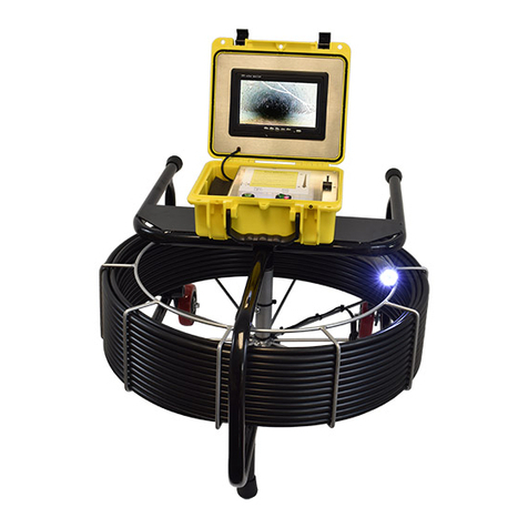
The large base frame is a powder coated steel frame with a
rugged aluminum reel designed to house 200’, 300’ and 400’ of
rigid (A) type rod. The entire IV2 system is powered from the
frame via AC power cord, DC power cord, or M18 Li-Ion battery
plug in and pressing the On button on the reel module. Also on
the module, you can adjust the intensity of the LEDs on the
camera head. The base frame includes an integrated digital
distance counter. The top part of the base frame includes a
mounting bracket for any of the IV2 command modules.
Push Rod
The push rod is .475” in diameter and has been specifically designed for longer pushing distances in 2”-12”
pipe. Attempts should not be made to push this rod type through 2” 90-degree bends as rod breakage may
occur. This rod type is available in 200’, 300’ and 400’ lengths on the large vertical base frame.
Debris Bag
The Debris bag is intended to minimize drippings while working indoors. It is easily removable for cleaning.
Battery (not included)
The IV2 does not come with the M18 battery 18V Li-Ion but it is available at your local home improvement or
hardware store.

19
AC Power Adaptor
The plug in for 110V to power up the system.
DC Power Adapter
The use the car power adapter to start up the system.
Video Interconnect Cord
The video inter-connect cord will need to be connected from the reel to the command module to display video.
Other manuals for IV2
1
Table of contents
Other Insight Vision Digital Camera manuals
