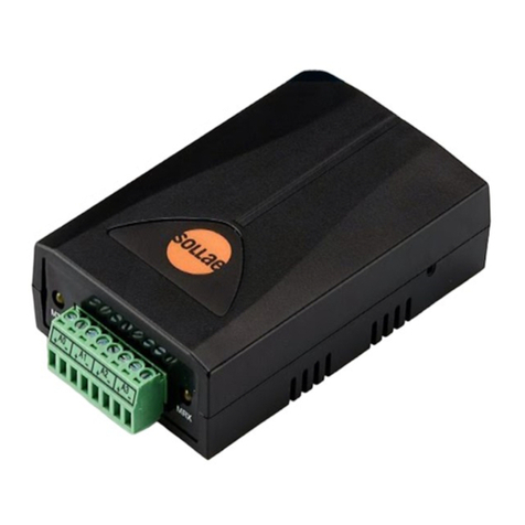
Insta KNX Gateway DMX-Web K.DMXGW.01 User manual

KNX Gateway DMX-Web K.DMXGW.01
KNX Gateway DMX-Web K.DMXGW.01
Art. no.: 135 16 112
Operating instructions
1 Safety instructions
Electrical devices may only be mounted and connected by electrically skilled persons.
Serious injuries, fire or property damage possible. Please read and follow manual fully.
These instructions are an integral part of the product, and must remain with the end customer.
2 Device components
Figure1
(1) DMX input (DMX IN – / DINX IN +)
(2) DMX output (DMX Out – / DMX Out +)
(3) DMX earth (GND)
(4) IP connection
(5) Status LEDs
(6) Programming LED
(7) KNX connection
(8) Programming button
(9) Connection for external supply
(10) Reset button
3 Function
System information
This device is a product of the KNX system and complies with the KNX directives. Detailed tech-
nical knowledge obtained in KNX training courses is a prerequisite to proper understanding.
1 / 7
82575434 06.02.2020

KNX Gateway DMX-Web K.DMXGW.01
Intended use
– Unidirectional data exchange between KNX and a DMX system
– Mounting on DIN rail to EN 60715
Product characteristics
The Gateway has two operating modes:
Operating mode "DMX master"
– Translation of KNX values into DMX data bytes
– Cyclic transmission of KNX values to the assigned DMX channels in the DMX bus with
250 kBit/s
– Control of RGB or RGBW luminaires via special logic modules
– Mapping of the functions switching (1-bit), relative dimming (4-bit) and absolute
dimming (1-byte)
– Master dimming object (1-byte) for channel groups
Operating mode "DMX slave"
– Reception of data bytes from the DMX bus
– Translation of the DMX data bytes into KNX values
Assignment between DMX channels and KNX group addresses is performed using a
table stored in the gateway. Assignment of the KNX group addresses and configuration of
the operating mode are performed using the Windows software DMX-Gate4 (or higher).
The current software as well as a detailed description of the commissioning can always
be found in the Internet.
Status LED (5)
Figure2
Power/Error Lit up green: Normal operation.
Orange flashing: Invalid project or no project.
Red flashing: Invalid firmware.
LAN Lit up yellow: Reception via the IP interface.
DMX Flashing green: Receiving/transmitting via the
DMX interface.
Lit up red: No receiving/transmitting of valid
DMX telegrams for one second.
KNX RX/TX Flashing green: Reception from the KNX bus.
Flashing red: Transmitting to the KNX bus.
Flashing red/green: No KNX bus detected.
Reset button (10)
The gateway is restarted by pressing the reset button (10). All stored configurations remain un-
changed.
2 / 7
82575434 06.02.2020

KNX Gateway DMX-Web K.DMXGW.01
4 Information for electrically skilled persons
4.1 Fitting and electrical connection
DANGER!
Electrical shock on contact with live parts in the installation environment.
Electrical shocks can be fatal.
Before working on the device, disconnect the power supply and cover up live parts
in the working environment.
General notes
Use data cable with 120 ohm characteristic impedance (e.g. CAT 5, 6, 7 network cable) for the
DMX bus.
Use a common wire pair each for the signals DMX In + / - and DMX Out + / -.
Do not use the terminal pairs DMX In and DMX Out to loop through a DMX signal. The terminal
pairs are only used individually depending on the operating mode.
Do not wire DMX bus in a star configuration.
Only use power supply units that supply secure extra low voltage SELV for power supply.
Connecting the device – operating mode "DMX master"
Figure3
In the operating mode "DMX master" the gateway functions as a DMX data generator. The ter-
minals DMX Out and GND are used for connection to the DMX bus.
Connect a maximum of 32 devices per gateway.
Only a single data generator is permitted in a DMX system. In order to combine the gate-
way with an additional DMX data generator (e.g. a DMX lighting console), a so-called
"DMX merger" is required.
■ Connect DMX bus to the terminals DMX Out + and DMX Out - (2) and GND (3).
■ Connect KNX bus to the KNX terminals (7).
3 / 7
82575434 06.02.2020

KNX Gateway DMX-Web K.DMXGW.01
■ Connect external power supply to one of the two terminal pairs AC/DC 24 V (11).
Connecting the device – operating mode "DMX slave"
Figure4
In the operating mode "DMX slave" the gateway functions as a DMX receiver. The terminals
DMX In and GND are used for connection to the DMX bus. When additional receivers are con-
nected to the DMX bus the DMX cable has to be continued over terminals DMX In and GND
(Figure 4). Do not use DMX Out terminals.
■ Connect DMX bus to the terminals DMX In + and DMX In - (2) and GND (3).
■ Connect KNX bus to the KNX terminals (7).
■ Connect external power supply to one of the two terminal pairs AC/DC 24 V (11).
Connecting the terminating resistor
(operating mode "DMX slave" only)
Figure5
A DMX bus should be provided with a terminating resistor at its last device. Otherwise, reflex-
ions at the end of the cable can lead to signal distortions.
4 / 7
82575434 06.02.2020

KNX Gateway DMX-Web K.DMXGW.01
Terminate cables only with the supplied terminating resistor (11).
Only provide a DMX bus with a terminating resistor if the gateway is the last device in the
DMX bus line.
There may never be more than one terminating resistor on a DMX bus.
■ Connect terminating resistor (11) to terminals DMX In + und DMX In - parallel to the DMX
bus line.
Looping through external power supply
Both terminal pairs (9) can be used for looping through the external power supply (Figure 6).
The total power consumption of all looped-through loads must not exceed 1.5 A.
Figure6
4.2 Commissioning
Commissioning
The gateway is commissioned via a Windows PC and the DMX-Gate4 software (or higher). The
current software including the related documentation can always be found in the Internet at
www.insta.de.
The IP interface serves to connect the PC to the gateway. A crosslink-network cable might have
to be used for the direct connection.
■ Connect PC to the gateway via IP connection.
■ Switch on PC.
■ Switch on external power supply.
■ Wait until the status LED Power/Error flashes orange.
■ Start DMX-Gate4 software and follow the instructions on the screen.
Load physical address
The physical address is loaded with ETS or with DMX-Gate4.
When assigning the physical address with ETS, proceed as follows:
■ Switch on the KNX bus voltage.
■ Press the programming button (8) (Figure 1).
■ Download physical address to the device with the ETS.
The KNX group addresses are assigned by means of the software DMX-Gate4. A plug-in
ensures the synchronisation of the group addresses with the associated ETS project
(from ETS4 onwards). Alternatively, use a dummy application for creating the filter tables
correctly.
The assignment of the physical address with DMX-Gate4 is described in the software
documentation.
5 / 7
82575434 06.02.2020

KNX Gateway DMX-Web K.DMXGW.01
5 Technical data
External supply
Rated voltage AC/DC24 V SELV (± 10%)
Mains frequency 50 / 60 Hz
Power consumption max. 2.0 VA
Ambient conditions
Ambient temperature -5 ... +45 °C
Storage/transport temperature -25 ... +70 °C
Protectionclass III
Fitting width 72 mm / 4 module
Weight approx. 175 g
Network communication
IP transmission rate 10 / 100 Mbit/s
IP connection mode RJ45 socket
KNX
KNX medium TP
Commissioning mode S-mode
Rated voltage KNX DC 21 ... 32 V SELV
Connection mode KNX Standard KNX/EIB connection terminals
Current consumption KNX max. 5 mA
DMX
Input interface USITT DMX512-A
Output interface USITT DMX512-A
Connection of power supply and DMX
Connection mode Screw terminal
single stranded 0.5 ... 4 mm²
Finely stranded without conductor sleeve 0.34 ... 4 mm²
Finely stranded with conductor sleeve 0.14 ... 2.5 mm²
6 Warranty
We reserve the right to make technical and formal changes to the product in the interest of tech-
nical progress.
We provide a warranty as provided for by law.
Please send the unit postage-free with a description of the defect to our central customer ser-
vice office:
Insta GmbH
Service Center
Hohe Steinert 10
58509 Lüdenscheid
Germany
6 / 7
82575434 06.02.2020

KNX Gateway DMX-Web K.DMXGW.01
Insta GmbH
Postfach 1830
D-58468 Lüdenscheid
Telefon +49 (0) 2351 936-0
Telefax +49 (0) 2351 936-1780
www.insta.de
7 / 7
82575434 06.02.2020
This manual suits for next models
1
Table of contents

