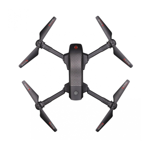
InstantEye Mk-3 GEN4-D1 User manual

InstantEye Mk-3 GEN4-D1 sUAS Technical Manual
Revision
M1.2
August 14, 2019
COPYRIGHT ©2018 InstantEye Robotics, a division of Physical Sciences Inc.
ITAR or EXPORT CONTROLLED
Page 1
InstantEye Mk-3 GEN4-D1
Product Manual
Revision M1.2
August 14, 2019

InstantEye Mk-3 GEN4-D1 sUAS Technical Manual
Revision
M1.2
August 14, 2019
COPYRIGHT ©2018 InstantEye Robotics, a division of Physical Sciences Inc.
ITAR or EXPORT CONTROLLED
Page 2
THE InstantEye Mk-3 GEN4-D1 IS A Small UNMANNED AERIAL SYSTEM
(sUAS) CAPABLE OF CAUSING PROPERTY DAMAGE AND BODILY HARM TO THE
OPERATOR AND OTHER PERSONS IF NOT OPERATED RESPONSIBLY. THIS
PRODUCT IS NOT DESIGNED FOR RECREATIONAL OR SPORT USE. An improperly
maintained aircraft can fail without warning. In manual mode, the InstantEye Mk-3 GEN4-
D11 will not hold position without constant corrections by the operator. Therefore, the
operator must use extra caution in this mode to ensure the aircraft remains under control
to avoid property damage or bodily harm.
High-capacity rechargeable lithium-polymer (Li-Po) batteries are the main power
source for the InstantEye Mk-3 GEN4-D1 system and can cause fire if handled
improperly. Proper handling techniques and precautions must be taken in order to avoid
creating a hazardous situation. READ AND UNDERSTAND THE BATTERY SAFETY
INFORMATION CONTAINED WITHIN THIS MANUAL BEFORE YOU ATTEMPT TO
CHARGE OR USE THE SUPPLIED BATTERIES.
This manual is a supplement to Federal Aviation Administration (FAA) regulations and
other guidelines applicable to unmanned aerial vehicle (UAV) operators. Operators
should be familiar with 14 CFR91.111, Operating Near Other Aircraft, 14 CFR 91.113
Right-of-Way Rules, 14 CFR 91.155 Basic VFR Weather Minimums, and any other
applicable regulations. Additionally, UAV operators may be subject to Department of
Defense (DoD) micro-unmanned aerial system regulations or other installation-specific
regulations.
Certificate of Authorization
It is the responsibility of the operator to obtain necessary authorizations, certifications,
licenses, or permits from the Federal Aviation Administration and local authorities and
jurisdictions as applicable. These agencies may have rules that limit or prohibit the use of
UAVs. Further, the Federal Communications Commission (FCC), state, and local
authorities may have rules prohibiting or limiting the use of video and/or radio
communications equipment.
Limitation of Liability
Your use of the InstantEye system is entirely at your own risk. InstantEye Robotics, a
division of Physical Sciences Inc., will not be responsible to you or to any third parties for
any direct or indirect, consequential, special, or punitive damages or losses you may incur
in connection with the InstantEye system, your use thereof, or any of the data or other
materials transmitted through or residing within the InstantEye system, regardless of the
type of claim or the nature of the cause of action.

InstantEye Mk-3 GEN4-D1 sUAS Technical Manual
Revision
M1.2
August 14, 2019
COPYRIGHT ©2018 InstantEye Robotics, a division of Physical Sciences Inc.
ITAR or EXPORT CONTROLLED
Page 3
Table of Contents
Table of Contents ................................................................................................ 3
1.
System Overview .......................................................................................... 6
1.1.
Aircraft........................................................................................................ 7
1.2.
Ground Control System............................................................................ 8
1.3.
Transit (Hard) Case ................................................................................... 8
1.4.
Soft Case.................................................................................................... 9
1.5.
Battery, 1.3 Ah & 5.7Ah ................................................................................... 9
1.6.
Battery Charger ....................................................................................... 10
1.7.
Charger Interface Cable for Ba-5590 & Bb-2590................................... 11
1.8.
Spares Kit ..............................................................................................12
2.
Safety ........................................................................................................... 13
2.1.
General Operations Safety ..................................................................... 13
2.2.
Aircraft Safety.......................................................................................... 13
2.3.
Battery Safety .......................................................................................... 14
3.
System Operation ....................................................................................... 15
3.1.
Overview .................................................................................................. 15
3.1.1.
Aircraft .................................................................................................... 15
3.1.2.
Ground Control System......................................................................... 16
3.1.3.
GCS Interface ......................................................................................... 17
3.1.4.
Flight Modes Overview .......................................................................... 18
3.1.5.
InstantEye Application On-Screen Display ......................................... 19
3.1.6.
Radio Frequencies ................................................................................. 24
3.2.
Pre-Flight.................................................................................................. 25
3.2.1.
Conditions Check................................................................................... 25
3.2.2.
System Inspection ................................................................................. 26
3.2.3.
Battery and Antenna Orientation.......................................................... 26
3.2.4.
Antenna Positioning .............................................................................. 27
3.2.5.
Video Output........................................................................................... 27
3.2.6.
Power On / Pairing ................................................................................. 27
3.3.
Initialization.............................................................................................. 28
3.4.
Launch...................................................................................................... 29
3.5.
Flight......................................................................................................... 29
3.5.1.
Endurance............................................................................................... 30
3.5.2.
Range ...................................................................................................... 30
3.5.3.
Altitude.................................................................................................... 30

InstantEye Mk-3 GEN4-D1 sUAS Technical Manual
Revision
M1.2
August 14, 2019
COPYRIGHT ©2018 InstantEye Robotics, a division of Physical Sciences Inc.
ITAR or EXPORT CONTROLLED
Page 4
3.5.4.
Video Feed .............................................................................................. 31
3.5.5.
Modes...................................................................................................... 31
3.6.
Landing .................................................................................................... 33
3.7.
Post-Flight................................................................................................ 33
3.8.
Video or Snapshot Playback .................................................................. 33
3.9.
Optional Return-to-Base Waypoint Entry ............................................. 35
3.10.
Optional Preprogrammed Waypoint Mission Entry ............................. 37
3.11.
Execute Preprogrammed Waypoint Mission ........................................ 38
4.
Warnings and Emergency Procedures ..................................................... 41
4.1.
Warning Messages.................................................................................. 41
4.2.
Loss of Video........................................................................................... 42
4.3.
Weak C2 Link ........................................................................................... 42
4.4.
Loss of Aircraft Gps Fix.......................................................................... 43
4.5.
Compass Heading Error ......................................................................... 43
4.6.
Flight Time Remaining is Critically Low ............................................... 43
4.7.
Collision Imminent and Unavoidable .................................................... 44
4.8.
GCS is Powered Off While Aircraft is in Flight ..................................... 44
4.9.
High Wind................................................................................................. 44
5.
Stowage ....................................................................................................... 45
6.
Maintenance ................................................................................................ 47
6.1.
Aircraft Maintenance............................................................................... 47
6.2.
GCS Maintenance .................................................................................... 49
6.3.
Battery and Battery Charger Maintenance ........................................... 49
6.4.
Tablet Charging ....................................................................................... 53
7.
Payloads ...................................................................................................... 54
7.1.
IR Floodlight Payload.............................................................................. 54
7.2.
Tactical Standoff Payload....................................................................... 56
8.
Troubleshooting.......................................................................................... 60
8.1.
Motor Does Not Spin............................................................................... 60
8.2.
Motor Shakes Violently........................................................................... 60
8.3.
Flight Time is Much Lower Than 20 to 30 Minutes ............................... 60
8.4.
Increased Wobble During Flight ............................................................ 60
8.5.
Aircraft is Louder than Usual ................................................................. 61
8.6.
Aircraft Does Not Pair with Gcs ............................................................. 61
8.7.
Limited Video Range............................................................................... 61
8.8.
GCS Powers Off Without Pressing Power Button................................ 61

InstantEye Mk-3 GEN4-D1 sUAS Technical Manual
Revision
M1.2
August 14, 2019
COPYRIGHT ©2018 InstantEye Robotics, a division of Physical Sciences Inc.
ITAR or EXPORT CONTROLLED
Page 5
8.9.
Aircraft Pulls to One Direction Consistently ........................................ 62
9.
Quick Start Guide........................................................................................ 63
9.1.
Prepare Tablet for Use ............................................................................ 63
9.2.
Wait for System to Pair........................................................................... 63
9.3.
View Video Feed ...................................................................................... 64
9.4.
Fly the System ......................................................................................... 64
10.
Warranty....................................................................................................... 65
11.
Revision Log................................................................................................ 66
12.
Reference Material ...................................................................................... 67

InstantEye Mk-3 GEN4-D1 sUAS Technical Manual
Revision
M1.2
August 14, 2019
COPYRIGHT ©2018 InstantEye Robotics, a division of Physical Sciences Inc.
ITAR or EXPORT CONTROLLED
Page 6
1. System Overview
The InstantEye Mk-3 GEN4-D1 sUAS is part of a family of high-performance, low-cost,
autonomous aerial systems that can be hand-launched/recovered by a single operator.
The GEN4-D1 leverages the combat-proven GEN3 and GEN4 systems’ ease of use and
survivability, combined with an encrypted software-defined radio, to provide an almost
silent, small, on-demand, local (approximately 3000 meters) situational awareness. As a
soldier’s end-user device, the InstantEye Mk-3 GEN4-D1 enhances force protection and
mitigates operational risk to everyone within its range.
The aircraft has integrated, gimbaled electro-optical (EO) and Long Wave Infrared (LWIR)
cameras. The aircraft’s small rotor span in flight makes it ideal as an entry robot, providing
the first eyes into an otherwise GPS-denied space. The system typically has
approximately 30 minutes endurance, which is affected by weather conditions (especially
wind, heat, and humidity), and any payload in use. The system is capable of flying in
inclement weather, including winds up to 35 mph, heavy rain/snow, altitudes up to 12,000
feet above mean sea level (MSL), and temperatures between -10°F and 120°F.
The system’s autopilot, flight controls, and human/robot interface have lineage from the
combat-proven InstantEye Mk-2 GEN3 and Mk-2 GEN4 systems. These earlier systems
have thousands of documented flight hours, have Air Worthiness Releases from Army
Special Operations Aviation Command, and are authorized for fielding and use by
Headquarters Department of the Army.
An InstantEye Mk-3 GEN4-D1 (MIL) system consists of the following elements (Figure 1):
•Aircraft, InstantEye Mk-3 GEN4-D1 (MIL) – QTY 2
•Two-Handed Controller (GCS-D) D1 (MIL) – QTY 1
•Ruggedized Ground Control System (GCS) Display (8J) – QTY 1
•GCS Cables w/ USB host adapter (8J) – QTY 1
•Transit (Hard) Case, InstantEye Mk-3 GEN4-D1 System– QTY 1
•Soft Case, InstantEye Mk-3 GEN4-D1*– QTY 1
•Battery, 1.3 Ah- QTY 2 /5.7V– QTY 2
•Battery Charger, InstantEye Mk-3 GEN4-D1 – QTY 1
•Charger Interface Cable for BA-5590 & BB-2590, 4-Pin – QTY 1
•Spares Kit, InstantEye Mk-3 GEN4-D1 – QTY 1
•InstantEye Mk-3 GEN4-D1 sUAS Technical Manual (MIL) – QTY 1
* Soft cases are available in multiple colors.

InstantEye Mk-3 GEN4-D1 sUAS Technical Manual
Revision
M1.2
August 14, 2019
COPYRIGHT ©2018 InstantEye Robotics, a division of Physical Sciences Inc.
ITAR or EXPORT CONTROLLED
Page 7
Figure 1. InstantEye Mk-3 GEN4-D1 system with transit case and soft case.
1.1. Aircraft
The InstantEye Mk-3 GEN4-D1 aircraft is a small, all-electric hand-launched/recovered
unmanned quadrotor aerial vehicle (Figure 2). It comes standard with a gimbaled two-
camera (EO/IR) video camera pod. See Section 7. Payloads (pg. 54) for details on each
payload.
Figure 2. InstantEye Mk-3 GEN4-D1 aircraft.

InstantEye Mk-3 GEN4-D1 sUAS Technical Manual
Revision
M1.2
August 14, 2019
COPYRIGHT ©2018 InstantEye Robotics, a division of Physical Sciences Inc.
ITAR or EXPORT CONTROLLED
Page 8
1.2. Ground Control System
The InstantEye Mk-3 GEN4-D1 Ground Control System (GCS) comprises a two-handed
controller (GCS-D), a ruggedized viewing device, and associated cabling with USB host
adapter. The viewing device in the standard configuration is an 8-inch Android-based
viewing device in a ruggedized case with a sunshade (Figure 3). The system is operable
with Nett Warrior and Android Tactical Assault Kit (ATAK). Video from the aircraft can be
recorded directly to the GCS-D memory.
Figure 3. InstantEye Mk-3 GEN4-D1 Ground Control System.
1.3. Transit (Hard) Case
The transit case (Figure 4), made of high-performance injection-molded plastic with
customized foam inserts, is designed to carry the full InstantEye system and has
provisions for additional batteries, payloads and spares. This ruggedized, water-resistant
case is designed to protect the system during shipment.
Figure 4. InstantEye Mk-3 GEN4-D1 system transit case.

InstantEye Mk-3 GEN4-D1 sUAS Technical Manual
Revision
M1.2
August 14, 2019
COPYRIGHT ©2018 InstantEye Robotics, a division of Physical Sciences Inc.
ITAR or EXPORT CONTROLLED
Page 9
1.4. Soft Case
There is one soft case provided (Figure 5). Each zippered, nylon case comes with
customized padding to protect its contents. The case is designed to carry one aircraft, the
GCS-D, the tablet and cables, and up to six batteries. The case minimizes weight for field
operations, while still providing protection from damage. The cases are available in a
variety of colors, based on the application: multicam, coyote, and black.
Figure 5. InstantEye Mk-3 GEN4 soft case – shown in MultiCam.
1.5. Batteries, 1.3 Ah & 5.7 Ah
The InstantEye Mk-3 GCS-D batteries are Lithium-Polymer (Li-Po) batteries. The 1.3 Ah
battery (Figure 6) is used in the operation of the InstantEye GCS-D. The 5.7 Ah battery
(Figure 7) is the GEN4 aircraft battery.
Figure 6. InstantEye Mk-3 1.3 Ah GCS-D battery.

InstantEye Mk-3 GEN4-D1 sUAS Technical Manual
Revision
M1.2
August 14, 2019
COPYRIGHT ©2018 InstantEye Robotics, a division of Physical Sciences Inc.
ITAR or EXPORT CONTROLLED
Page 10
Figure 7. GEN4-D1 5.7 Ah aircraft battery.
1.6. Battery Charger
The InstantEye Mk-3 GEN4-D1 battery charger consists of a charge module, AC/DC
module, battery charging cradle, battery balancing cable (x2), and a battery charge
adapter (Figure 8).
Figure 8. InstantEye Mk-3 GEN4-D1 battery charger.

InstantEye Mk-3 GEN4-D1 sUAS Technical Manual
Revision
M1.2
August 14, 2019
COPYRIGHT ©2018 InstantEye Robotics, a division of Physical Sciences Inc.
ITAR or EXPORT CONTROLLED
Page 11
1.7. Charger Interface Cable for BA-5590 & BB-2590
This interface cable (Figure 9) enables the InstantEye batteries to be charged directly
from a user-provided BA-5590 or BB-2590 battery instead of the 12 V / 5 A power supply
provided as part of the system.
Figure 9. BA-5590 and BB-2590 charger interface cable.

InstantEye Mk-3 GEN4-D1 sUAS Technical Manual
Revision
M1.2
August 14, 2019
COPYRIGHT ©2018 InstantEye Robotics, a division of Physical Sciences Inc.
ITAR or EXPORT CONTROLLED
Page 12
1.8. Spares Kit
The InstantEye Mk-3 GEN4-D1 spares kit (Figure 10) provides spares for those
components that can be easily replaced by the operator in the field. The kit consists of:
•Replaceable motor assembly “O” (QTY 2)
•Replaceable motor assembly “X” (QTY 2)
•Motor screw (QTY 16) *note these come pre-installed in the motors
•Propeller kit (QTY 1)
–Propeller “O” (QTY 2)
–Propeller “X” (QTY 2)
–Propeller nut (QTY 4)
•Screwdriver, #1 Phillips (QTY 1)
•Nut Driver, 10 mm (QTY 1) for ISR; 8mm for HL
Figure 10. InstantEye Mk-3 GEN4 spares kit. Note that the motor screws ship installed on
the motor assemblies, so they aren’t shown separately above.

InstantEye Mk-3 GEN4-D1 sUAS Technical Manual
Revision
M1.2
August 14, 2019
COPYRIGHT ©2018 InstantEye Robotics, a division of Physical Sciences Inc.
ITAR or EXPORT CONTROLLED
Page 13
2. Safety
2.1. General Operations Safety
The InstantEye Mk-3 GEN4-D1 system should never be used in a scenario where it could
imperil the safety of manned aircraft.
All FAA rules and regulations must be observed while flying in civilian airspace, and all
Department of Defense (DoD) and installation-specific rules and regulations must be
followed in military airspace. Do not fly in controlled airspace or over property without
prior permission from the manager/owner of that airspace/property.
For detailed information about possible emergency scenarios during flight and the
standard recovery procedures, refer to Section 4. Warnings and Emergency Procedures
(pg. 41).
2.2. Aircraft Safety
The aircraft is equipped with four hard-composite propeller blades that spin at or above
6000 RPM. Keep hands and face clear of the propellers at all times while the aircraft is
powered. Loose clothing and long hair could become entangled in spinning propellers and
should be constrained before operation of the aircraft. The aircraft should not be flown
near tree branches, hanging wires, or other obstructions that could catch in the propellers.
When the motors are on the operator must always be able to reach the MOTOR button
located on the GCS to immediately shut them off in an emergency. Never leave the GCS
outside of arm’s reach while the motors are running.
Although the aircraft can maintain position and altitude autonomously, the operator should
never leave the GCS unattended, except to service an unrelated emergency and should
resume operation of the GCS immediately thereafter.
The aircraft is capable of high-speed travel and could cause bodily harm and/or damage
to property should it collide with a person or object in flight. No one should operate the
InstantEye Mk-3 GEN4-D1 system without proper training. Personnel should wear
safety glasses and head protection during training.
If a crash is imminent, turn off the motors as quickly as possible to minimize damage. A
crash with the motors on is much worse than a crash with the motors off. Avoid flying in
close proximity to people and high-value property.
The aircraft is not designed to fly in winds in excess of 35 mph. It is dangerous to fly in
these conditions, as the flight controls may be adversely impacted. Although the aircraft
can fly in rain, for the operator’s own protection, it should never be flown when there is
lightning in close proximity.
Using pre-flight checklists, inspect the aircraft for damage before and after every flight,
and especially following hard landings. Replacement of damaged parts, if possible, should
be done immediately and only with those replacements supplied by the manufacturer.
When flying the aircraft again for the first time after a crash, the operator must be
especially attentive in case of a controls malfunction due to hidden damage.

InstantEye Mk-3 GEN4-D1 sUAS Technical Manual
Revision
M1.2
August 14, 2019
COPYRIGHT ©2018 InstantEye Robotics, a division of Physical Sciences Inc.
ITAR or EXPORT CONTROLLED
Page 14
2.3. Battery Safety
Both the aircraft and the GCS are powered using high-capacity lithium-polymer (Li-Po)
batteries. As with all Li-Po batteries, the following scenarios should be adhered to:
•Stay within the specified temperature range
•Avoid mechanical damage
•Never connect the batteries to any other charger other than those provided by the
manufacturer
•Batteries that appear swollen or have been mechanically damaged must be
disposed of in accordance with local and Federal regulations
•Never leave a battery in a parked vehicle in the sun on a hot day
Use only the batteries provided with the InstantEye Mk-3 GEN4-D1 system and only
charge them with the supplied charger. Batteries should always be monitored while
charging and kept away from flammable materials.
Charge aircraft batteries after every use. Charge the GCS-D battery after every two
aircraft flights, or as indicated by the boot-up screen. Continued use of discharged
batteries can cause permanent damage. Never allow a Li-Po battery to short circuit.
If the battery life of the aircraft runs out during flight, the aircraft will descend rapidly
without input from the operator. If a serious crash occurs, inspect the Li-Po battery from
the aircraft on a non-flammable surface. Look for swelling of the battery or significant
damage to the wiring insulation. If either of these conditions is present, the battery must
be disposed of properly.
Continuing to use a damaged battery could result in a fire. InstantEye’s batteries will
function in temperatures between -10° to 120° Fahrenheit (-23°C to 49°C), but for optimal
performance should be kept between 15° and 100° Fahrenheit. A battery pack at a
temperature of less than 15°F (-9°C) can show noticeably poorer performance until it
warms up with use. In wintertime or in cold climates, store packs in a heated indoor living
space or in contact with your body heat. For outdoor use in cold climates, you should pre-
warm your packs to room temperature by storing in clothing pockets or a heated vehicle.
CAUTION! Never launch an aircraft with a battery that has been stored at a
temperature below 15° Fahrenheit (-9°C).
CAUTION! Li-Po batteries should never be exposed to temperatures in excess of
140° Fahrenheit (60°C).
Shipping Li-Po batteries must be in accordance with the U.S. Department of
Transportation's (DOT's) Hazardous Materials Regulations (HMR; 49 C.F.R., Parts 171-180).

InstantEye Mk-3 GEN4-D1 sUAS Technical Manual
Revision
M1.2
August 14, 2019
COPYRIGHT ©2018 InstantEye Robotics, a division of Physical Sciences Inc.
ITAR or EXPORT CONTROLLED
Page 15
3. System Operation
3.1. Overview
The InstantEye Mk-3 GEN4-D1 system is capable of supervisory (normal) and manual
(emergency) flight, depending on the flight mode selected by the operator. Typical flight
operation is more like positioning a camera in the sky than flying an aircraft. The operator
unpacks and powers the system, sets a flight altitude, and launches the aircraft. While in
the air, the aircraft maintains its altitude and position until the operator commands a change
with the GCS-D. The operator can toggle the current camera feed that is sent down and
displayed on the tablet.
3.1.1.
Aircraft
The InstantEye Mk-3 GEN4-D1 aircraft is a quadrotor configuration, vertical takeoff and
landing (VTOL), small unmanned aerial system (sUAS) designed for single-user
operations. The aircraft consists of two major assemblies: a plastic and carbon-fiber
frame, and a plastic-enclosed electronics body. See Figures 11 & 12 for labeled pictures
of the major aircraft components.
Figure 11. InstantEye Mk-3 GEN4-D1 aircraft components – top and bottom views.
The top surface of the body above the cameras contains the GPS antenna. This region
of the aircraft must be kept clean and free of tape or decals. Hook-pile tape straps are
provided on the bottom of the body for secure attachment of the 5.7 Ah battery.

InstantEye Mk-3 GEN4-D1 sUAS Technical Manual
Revision
M1.2
August 14, 2019
COPYRIGHT ©2018 InstantEye Robotics, a division of Physical Sciences Inc.
ITAR or EXPORT CONTROLLED
Page 16
Figure 12. InstantEye Mk-3 GEN4-D1 aircraft components – front and rear views.
3.1.2.
Ground Control System
The Ground Control System for the InstantEye Mk-3 GEN4-D1 consists of an Android
viewing device, a two handed controller (GCS-D) with battery, and the associatedcables
connecting the GCS-D to the viewing device. The GCS-D is weather-resistant and
connects through Series 80 Mighty Mouse Connectors and cables. Additional power can
be provided by a 10 Ah Li-Po battery soldier’s conformal wearable battery (CWB, not
included). See Figure 13 for a labeled picture of the major GCS components. More details
on the control interface are provided in Section 3.1.3. GCS-D Control Interface (pg.17),
and more details on the display of the viewing device are provided in Section 3.1.5. GCS
On-Screen Display (pg.19).
Figure 13. InstantEye Mk-3 GEN4-D1 GCS components.
8-inch Ruggedized Tablet
USB Host Adapter
Vehicle Specific
Module (GCS-D)
Series 80 Mighty Mouse
USB Connector
USB Cable

InstantEye Mk-3 GEN4-D1 sUAS Technical Manual
Revision
M1.2
August 14, 2019
COPYRIGHT ©2018 InstantEye Robotics, a division of Physical Sciences Inc.
ITAR or EXPORT CONTROLLED
Page 17
3.1.3.
GCS-D Interface
The GCS-D interface can be broken into three main groups: joysticks (QTY 2), wheel
(QTY 1), and buttons (QTY 10). Each of these interfaces (Figures 14 & 15) is described
below.
Figure 15. GCS-D button, wheel and joystick configuration – top view.

InstantEye Mk-3 GEN4-D1 sUAS Technical Manual
Revision
M1.2
August 14, 2019
COPYRIGHT ©2018 InstantEye Robotics, a division of Physical Sciences Inc.
ITAR or EXPORT CONTROLLED
Page 18
3.1.3.1.
Joysticks
There are two, four-position joysticks used to reposition the aircraft once it is airborne:
•The left joystick is the translation joystick. Pushing the translation joystick forward
moves the aircraft forward. Likewise, pushing the translation joystick rearward,
moves the aircraft backward. Pushing the translation joystick left or right moves
the aircraft laterally, left and right.
•The right joystick is the yaw/altitude joystick. Pushing the yaw/altitude joystick left
or right rotates the aircraft heading (yaw). Pushing the yaw/altitude joystick forward
increases the aircraft altitude and pushing the yaw/altitude joystick rearward
decreases the aircraft altitude.
3.1.3.2.
Camera Wheel
There is a wheel on the left underside of the GCS-D. This wheel gimbles the camera.
3.1.3.3.
Primary Control Buttons
The ten control buttons and their function are as follows:
•ALT button enables and disables Altitude Control mode
•NAV button enables and disables Navigation Control mode
•CAMERA button toggles the current video feed that is displayed on the GCS
•MOTOR button turns the aircrafts motors on and off
•HOME button enables Home mode
•UTILITY 1 button tilts the gimbaled camera upward
•UTILITY 2 button tilts the gimbaled camera downward
•UTILITY 3 button controls payload functions
•UTILITY 4 button controls payload functions
•POWER button turns the GCS-D on/off
3.1.4.
Flight Modes Overview
A brief description of the flight modes is given below to provide context for describing
other aspects of the aircraft. A full description of the modes will follow in the section titled
“Flight Modes.” Note the three standard, user-defined modes are shown throughout this
document with black text with green background.
•Navigation – Navigation, or NAV, mode activates the GPS translational position
controller.
•Altitude – Altitude, or ALT, mode activates the vertical position controller.
•Home – Home, or HOME, mode commands the aircraft to return to its home
location.
•Landing – Landing mode lands the aircraft at its home location during lost
communications. Landing mode can be activated by holding down the HOME
button.
•Lost Communications – Lost communications mode is enabled automatically
when the aircraft fails to receive commands from the GCS. Note, this is not a
user-activated mode.

InstantEye Mk-3 GEN4-D1 sUAS Technical Manual
Revision
M1.2
August 14, 2019
COPYRIGHT ©2018 InstantEye Robotics, a division of Physical Sciences Inc.
ITAR or EXPORT CONTROLLED
Page 19
3.1.5.
InstantEye Application On-Screen Display
When the InstantEye application (app) is enabled, the on-screen display (OSD) provides
the operator with important data from the aircraft and GCS in a visual format. This
information is displayed in several graphics, each of which is shown in the following
example image (Figure 16). In this section, the function of each graphic is explained in
detail.
Figure 16. Ground control system on-screen display with graphics.
3.1.5.1.
Range/Bearing
The Range/Bearing graphic (Figure 17) is in the upper left of the display screen. It displays
the distance from the GCS to the aircraft in meters, the direction of the aircraft from the
GCS, and the bearing of the aircraft relative to the operator.
Figure 17. Range/Bearing graphic.

InstantEye Mk-3 GEN4-D1 sUAS Technical Manual
Revision
M1.2
August 14, 2019
COPYRIGHT ©2018 InstantEye Robotics, a division of Physical Sciences Inc.
ITAR or EXPORT CONTROLLED
Page 20
When the aircraft has a GPS fix, a number followed by the unit “m” (meters) will appear
inside the inner circle. This is the approximate range from the GCS to the aircraft. If the
range is less than 5 meters, “<5m” will display. If the aircraft does not have a fix, an “X”
will display in the center of the inner circle.
The line drawn from the outside of the inner circle to the inside of the outer circle indicates
the direction to the aircraft from the GCS. It “points” in the direction of the aircraft (Figure
18). If the aircraft does not have a GPS fix, the direction cannot be calculated and the line
will not be displayed.
Figure 18. Range/Bearing graphic example.
The line drawn starting from the outer circle indicates the bearing of the aircraft relative
to the operator. If the aircraft is “facing” away from the operator (i.e., if it were to be moved
forward, the range would increase), this line will form a continuation of the other line. If the
aircraft is pointed back towards the operator, this line will “fold back” in on the other line.
Note: Should the operator move with the GCS while it does not have a GPS fix, the range
and direction information will be incorrect. The further the operator moves from the aircraft
launch location without a GCS GPS fix, the greater the error in the displayed information.
Note: Upon startup, if the Range/Bearing graphic gives an erroneous range or direction,
wait for the GCS GPS fix to improve before launching.
3.1.5.2.
Heading
The Heading graphic (Figure 19) indicates the aircraft’s magnetic heading in degrees.
The scrolling text above the numerical heading inside the grey box mimics a compass
card and allows the operator to discern quickly what bearing may be achieved by yawing
left or right.
Table of contents
