SYMA X14W User manual

14+
GYRO REMOTE CONTROL SERIES
4-CHANNEL PRESSURE HOVERING HEIGHT-ADJUSTMENT
REMOTE CONTROL 6-AXIS FLYCOPTER
1USER MANUAL
OPERATING STANDARDS: GB/T26701-2011
MAIN FEATURES
● Utilises the 4-axis structure, enabling the aircraft to be even more
flexible, speedy,and possessing a relatively stronger wind-withstanding
capability. Also it can conduct flights in interior as well as exterior
environment.
● A 6-axis gyro direction stabiliser is built-in, ensuring precise positioning
in the air.
● The structure uses modular designs, making installation simple and
repair and maintenance easier.
● Capable of 360° 3D overturning function.
● Headless function is enabling the aircraft to be summoned back with ease.
● Brand new pressure hovering height-adjustment function.
● New functions increased are one key take off/landing .
● HD wifi real-time transmission aerial.
X14W
(720P)

-1-
The content, specifications or accessory packaging of internal products
in this user manual is strictly for reference only. Our company will not be
responsible for errors in the printed contents and it will not be able to
proactively notify the consumers. For any updates or errors, please abide
by the SYMA MODEL AIRCRAFT’s website as accurate.
1. Please store the smaller-sized aircraft accessories in places that are
out of reach of children, in order to avoid the occurrence of accidents.
2. This aircraft is very powerful. For all first-time flight, it shall be
observed that the left gear shift joystick must be slowly pushed in
order to prevent the aircraft from ascending too quickly and result in
unnecessary collision and damages.
3. When the flight is ended, the power supply of the remote control shall
be switched off firstly, and then, followed by the switching off of the
power supply of the aircraft.
4. Avoid placing the batteries in places with high temperatures and
exposure to heat (for example, naked light or electrical equipment
installations).
5. Take extra precaution to ensure that the aircraft is at a distance of 2 to
3 metres from the user or other people in order to prevent the aircraft
from colliding into the head, face or body, etc. of other people during
landing.
6. When young children are operating the aircraft, it shall be ensured that
the adults are guiding and making sure that the aircraft control is
within the viewing range of the controller (or instructor) such that it
makes the control very convenient.
7. Non-rechargeable batteries are prohibited for recharging. When
installing or changing the batteries, please take extra care on the
polarities of the batteries; mixing new and old batteries or different
types of batteries are strictly disallowed.
8. When the aircraft is not in use, please switch off the power supplies
of both the aircraft and the remote control, and remove the batteries
in the remote control.
9. The terminals & power supply cannot be short-circuited.
Safety guide

-2-
1. Always use dry and soft cloth to clean this product.
2. Avoid this product to be exposed to sunlight or heat.
3. Avoid immersing these toys into water, otherwise ,the electronic
parts may be damaged.
4. Regularly Check and inspect the plug and other accessories. If any
damages are discovered, please immediately stop using it, until it is
completely repaired in good working condition.
Repair and maintenance
The following items can be found in this product package:
Package description
• Aircraft
• Remote Control
• Main Blade
• Instruction Manual
• Screwdriver
• Card Reader
• USB Cable
• Memory Card
• Mobile Phone Retaining Clip
Wifi real-time transmission aerial
photo-taking component installation
Mobile phone retaining clip installation:
2. Align the mobile
phone retaining clip
with the antenna of
the remote control
and insert it in.
3. Use strength to press
against the spring
section of the
retaining clip to
adjust the size.
1.Pressing on the mobile
phone clip cover behind
the remote control and
pushing it out upward.

-3-
Battery changing and charging
methods for aircraft
Precautions as follows during charging of battery:
- Avoid placing the active batteries in places with direct exposure,
sunlight and high temperatures. For example, naked light or electrical
equipment installations; otherwise it may cause damages or
explosions.
- Avoid immersing the batteries in the water. The batteries shall be
stored in a cool and dry place.
- Avoid dismantling the batteries.
- During the charging of battery, avoid leaving the charging place.
The charging time is less than 130 minutes; In hover flight
conditions longer than 6.5 minutes!
1. Shut down model
on the power switch.
3. Connect battery
disconnect with
dash receiver.
Battery changing step
Charging methods for aircraft
2. Open aircraft’s
battery cover
the pushed back.
4. After battery replacement,fasten the
battery cover again.
1. Connect the power supply line of the battery
with USB, and connect the USB interface
with the computer’s connection port (During
charging, the light indicator will light up; and
the light indicator will go off when it is fully
charged. The completion time for charging
the battery is less than 130 minutes).

-4-
Understanding your remote control
Remote control’s button function description:
Battery installation for remote control:
Power ON/OFF
Left function lever
(press and hold to
fine-tune the
adjustment, release
the complete exit / +
hold the power key,
trimming cleared)
Phone attaching clamp
Right function lever
(PressStart headless
mode / Short Press
the high-low speed
switching)
3D Eversion
Battery cover
4 x AA Batteries
One key take off/
One key landing

-5-
1. Battery Installation Method: Open up the battery cover at the back of
the remote control. Correctly place 4 x AA alkaline batteries in the
battery box in strict adherence to the polarity instructions (the
batteries are optional).
1. During the battery installation, it must be ensured
that the polarities of the batteries are matched with
that of the battery box. No battery shall be installed
with the opposite polarity.
2. Please do not use new and old batteries together.
3. Please do not use different types of batteries
together.
Product features
1. Low-voltage protection:
When the four indicator lights at the bottom of aircraft
start flicking, it means that the aircraft's battery power
is low. At this time, the aircraft will initiate the height-
limiting function and will drop to certain safety height.
2. Overcurrent protection:
When the aircraft encounters direct impact from foreign
object or is stuck under the circumstances in which its
blades are rotating, the electric circuit of the aircraft will
enter into the overcurrent protection mode.
3. Level calibration function:
Place the aircraft on a levelling surface and at the same
time, push both left and right joysticks to the lower right
corners and stay there for 2 to 3 seconds; the normal
light indicator on the aircraft will blink rapidly, and it will
return back to the normal status after about 2 to 3
seconds. The level calibration is successful.

-6-
When you are familiar with the basic actions, you
can proceed to explore even more exciting and risky
overturning actions. Fly the aircraft to a height of
above 3 m from the ground, press against the upper
right corner button (Overturning Button) on the remote
control and simultaneously push the right joystick to
the highest level of Front/Back/Left/Right, the aircraft
will now be executing the Front/Back/Left/Right
overturning function.
5. 3D overturning function:
Note: When the batteries are fully charged, it will have the best overturning effect.
6. Pressure hovering height adjustment function:
After using the left joystick (Accelerator) to
control the ascending / descending flight of the
aircraft, free up the left joystick (Accelerator) and
the aircraft will still hover at that height when
the joystick is freed.
7. Headless function:
1. Defining forward direction:
1. Open up the power supply switch of the
remote control.
4.Fast/slow gear function:
Slow gear by default on power-on. Possible to switch
the function mode of fast/slow gear by pressing on the
operating arm on the right side for a short time. It is
switched into fast gear mode when two “didi” sound
come from the remote control, pressing on the operating
arm on the right side for a short time under fast gear
mode and then one “di” sound would come from the
remote control, then it is then switched back into slow
gear mode.
3M

-7-
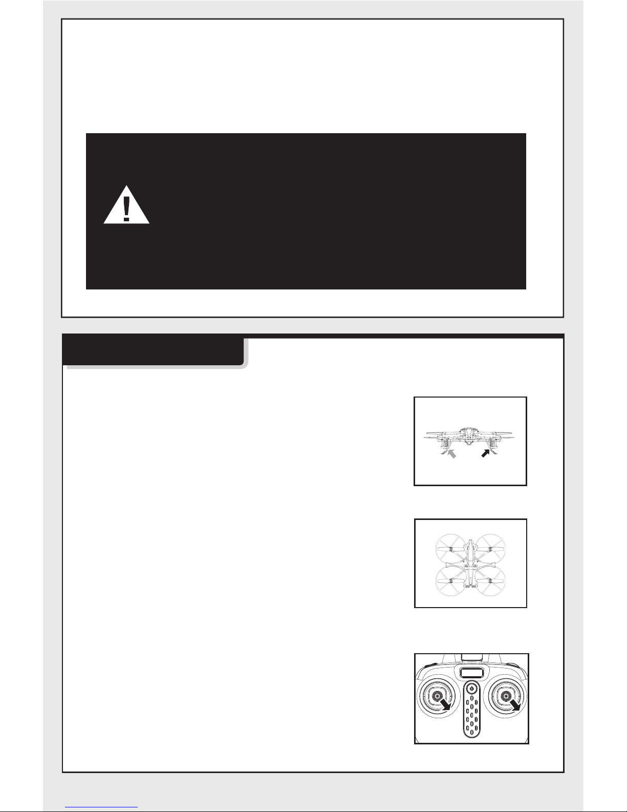
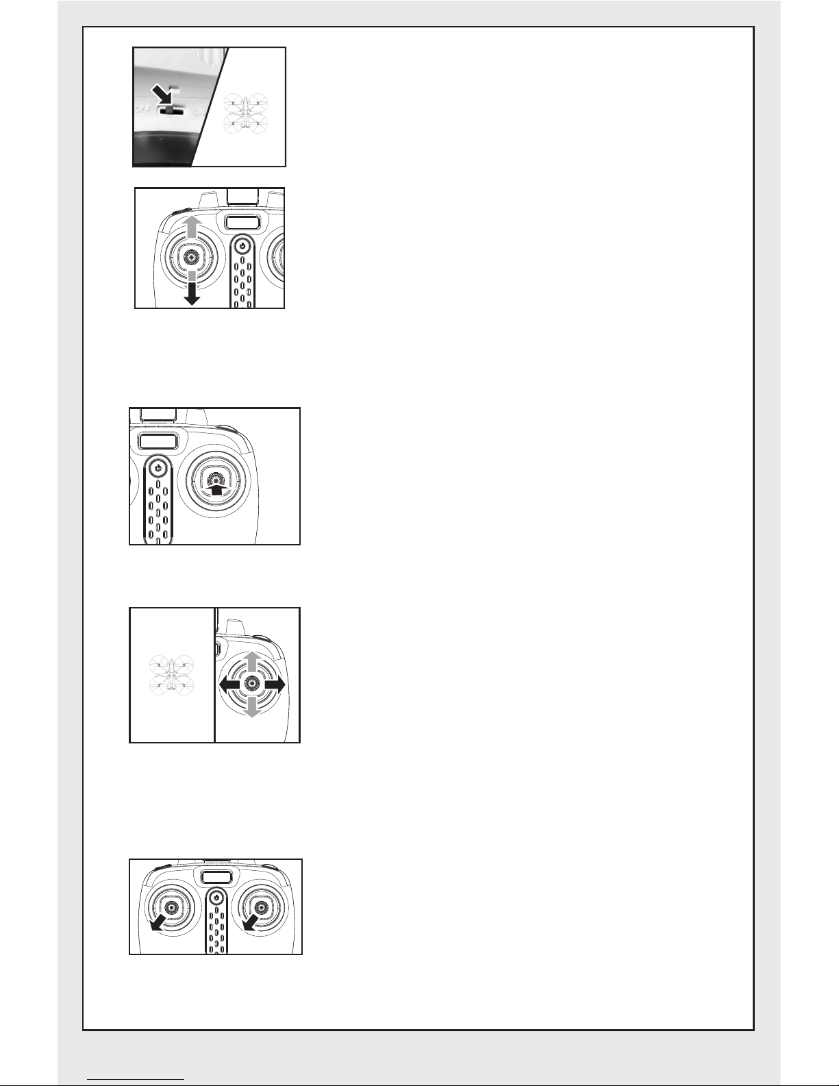
2. After connecting the aircraft to the power supply,
push the switch to “ON” location, and adjust the
specified direction of the aircraft’s head under the
headless mode as the new forward direction.
3. Push the accelerator joystick of the remote control
to the highest level and then, pull back into the lowest
level. When the remote control issues a long beep
sound, it means the frequency and defining forward
direction functions are completed.
Front
Back
Left Right
Front
Back
2. Toggling between headless function and normal function:
2. Under the headless mode, the operator does not
require to differentiate the head position of the
aircraft, and he just needs to control the aircraft
using the joystick’s direction of the remote control.
3. Rectification for the defining forward direction function:
1. When the aircraft encounters a direct impact with
foreign objects in the headless mode, if there is an
occurrence of deviation of the defined direction, it is
only required to push the accelerator and the
direction joystick to the left bottom corners
simultaneously after rectifying the flying direction of
the aircraft in the correction direction. When the light
indicator of the aircraft is in a long “ON” mode after
slowly blinking for3 seconds, it indicates the
rectification is complete.
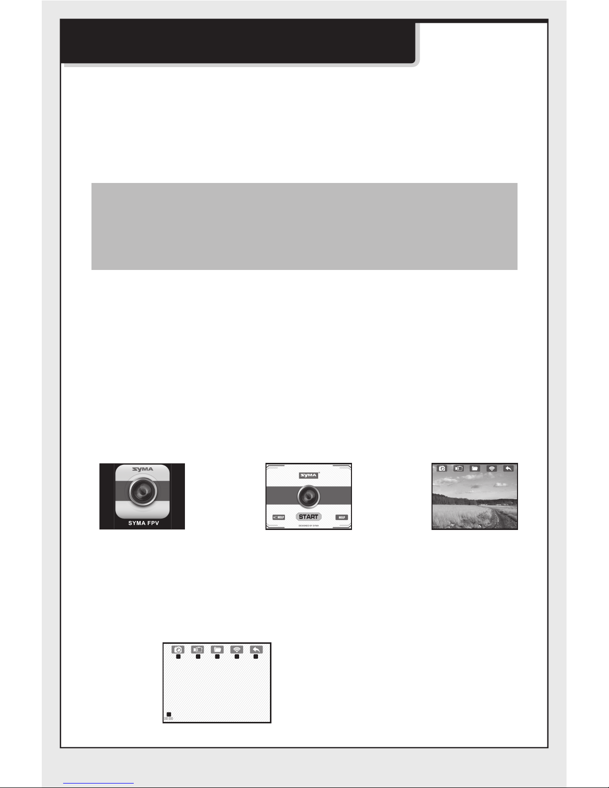
1. After the aerobat matched with the corresponding
frequency, the aerobat would be in normal pattern by
default. At this time the indicator light on the aerobat
would be in a state of on for a long time. After pressing
on the right operating arm of the remote control for 2
seconds, the remote control would make a sound of “di,
di, di,...” to show that it has entered into a state of ,
pressing on for 2 seconds then a long sound of “di”
would be heard to show an exit status. (When under the
state of , four indicator lights on the aerobat are recording
lights which flicker once every four seconds)
Left Right
Front
Back
Left Right

-8-
Wifi real-time transmission aerial
photo-taking component installation
1. Download the installation software:
2. Connection description:
For Android mobile phones, please kindly (visit www.symatoys.net) or scan the QR
code to download the SYMA FPV installation software.
For Apple mobile phones, please kindly proceed to APP STORE to download the
SYMA FPV installation software or scan the QR code to download the SYMA FPV
installation software.
Connect model power supply. The FPV light indicator is green and will become red
blinking light after approximately 20 seconds, awaiting the connection for mobile
phone. At this moment, click on “Settings” option in mobile phone and activate
WIFI. In the WIFI’s search column, look for “FPV WIFI ****” connection, and click
on connection until the message “has been connected” is shown, which indictes that
the connection is successful. Now, exit the “Settings” option. Open up the SYMA
FPV software, and click the “START” icon to enter into the control panel. The
mobile phone screen has entered into the real-time imaging scenarios. The full
bar of the WIFI’s signal indicates that the current signal is at its strongest.
1. Open up SYMA FPV
software.
2. Click on “START” icon. 3. The mobile phone
screen displays
with real-time
imaging scenarios.
3. Real-time transmission gui icon description
12345
6
1. Back
2. WIFI’s Signal
3. Checking of Photos and Videos
4. Video Recording
5. Photo-Taking
6. Video Recording Time Display
Warm remided: Two-dimension code is provided in color box
packing and back cover of specification to scan.Please
concern official website APP STORE of SYMA or the latest
reminder of Google play to acquire the latest SYMA FPV.

-9-
Flight preparation and switching
off of the aircraft
1. Flight preparation
Step 1: Open up the power supply switch
of the remote control.
Step 2. Open battery cover, and connect
battery connector with dash receiver.
4. Real-time transmission aerial photo-taking
5. Memory card storage function.
Photo-Taking and Video Recording: When the WIFI camera is
operating in normal conditions, please click on the photo or video
icon on the real-time transmission GUI, and immediately you can
conduct photo-taking or video recording. (The completed files for
photo-taking or video recording can be found in the “Checking of
Photos and Videos” files.)
This 720P WIFI camera has the function of memory card storage.
When 720P WIFI camera has the memory card, mobile phone and
memory card will store pictures/videos simultaneously. When 720P
WIFI camera has no memory card, pictures/cards are only stored in
a mobile phone.
Note: When activating the mobile phone software to conduct
real-time transmission operating mode, the flight
distance of the aircraft will be shortened by half!

-10-
Method 2: Move the left and right joysticks
inwards in an internal loop of “8” for 1
second, the ventilation blade of aircraft
starts rotating slowly.
Step 4.Pressing on the power switch on the
top of the aerobat to make sure the aerobat
in the state of “OFF”.
2. Switching no the aircraft
Method 1: push the left lever (accelerator) to
the highest point and then reset to the center,
the ventilation blade of aircraft starts rotating
slowly.
Step 5: Push the left lever (accelerator) to
the highest point and then reset to the lowest
point. When the indicator lights in the aircraft
change from quick flashing to the continuous
lighting, it means that the aircraft goes into
the flight standby mode.
B
Step 3. Enclose battery into the fuselage,
after closing battery cover,turn on the
switch on the bottom of aircraft.
Method 3: When the vehicle is stationary,
press the B button, the vehicle slowly
rotating blades, automatically rises to a
certain height.

-11-
B
3. Switching off the aircraft
Method 1: Push the left joystick (Accelerator)
to the lowest level and stay there for 2 to 3
seconds, the aircraft can then be switched
off.
Method 2: Move the left and right joysticks
inwards in an internal loop of “8” for 1
second, and the aircraft can be switched
off.
Method 3: When the aircraft is in flight, press
the B button, the aircraft fell to the ground
and slowly closed the aircraft.
Aircraft controlling diagram
Operating direction
Ascending and descending control Forward and backward control
When the left joystick (Accelerator) is
pushed upwards or downwards,the
aircraft will ascend or descend
correspondingly.
When the right joystick (Turning Rudder)
is pushed upwards or downwards, the
aircraft will advance forward or backward
correspondingly.

-12-
Left turning and right turning control
Left side flying and right side flying control
When the left joystick (Accelerator) is
pushed towards the left or right, the
aircraft will turn left or right
correspondingly.
When the right joystick (Turning Rudder)
is pushed towards the left or right, the
aircraft will fly sideward on the left or
right correspondingly.
Fine-tuning operation
Forward and backward fine-tuning control
Left/right side flying fine-tuning control
Left/right side turning fine-tuning control
Under the condition aerobat hovering in the air when aerobat
automatically flies forward/backwards, one could press down
the left operating arm and at the same time push the right
operating arm forward/backward to adjust the direction.
Don’t unloose the left operating arm until aerobat comes into
a stable state.
Under the condition aerobat hovering in the air when aerobat
automatically flies towards the left/right side, one could press
down the left operating arm and at the same time push the
right operating arm to the right/left to adjust the direction.
Don’t unloose the left operating arm until aerobat comes into
a stable state.
Under the condition aerobat hovering in the air when aerobat
automatically rotates and flies towards the left/right, one could
press down the left operating arm and at the same time push
the left operating arm to the right/left to adjust the direction.
Don’t unloose the left operating arm until aerobat comes into
a stable state.

-13-
Accessories (Optional)
You can choose your favourite optional accessories as below. In order
to make it easier for the customers to choose and purchase, we have
specially offered each and every accessory. The accessories can be
purchased through the local distributors. Please kindly specify the
colours during your purchase.
Main Body Rotor Blade
Motor CoverPlating ObjectMotor B
Black and White Line
Motor A
Red and Blue Line
Base StandProtective Gear
Memory card installation / removal
Memory card installation Memory card removal
1. According to the figure
memory card into the slot
in front of the aircraft.
Note: Do not remove or insert the aircraft powered memory card.
1. According to the figure
from the memory card
out of the slot on the front
of the aircraft.

-14-
USB
Battery
720P WIFI the
Camera Board
Battery CoverSquare Fiber Tube
Battery Box Receiver Board
Card Reader Mobile Phone
Fixed Mounting
Remote Control
Product descriptions
Motor Seat Fitting
Light Strip
01
06
04
03
18
18
11
07
09
13
11
08
09
15 16
09
07
11
14
11
03
04
18
18
08
09
10
12
17
12
12
12
02
05
05
05
05

-15 -
Main specifications
Aircraft’s Length:21.5cm Aircraft’s Width:24cm
Aircraft’s Height:7cm Motor’s Model: Ø7
Battery: 3.7V/500mAh lithium battery
01
02
03
04
05
06
07
08
09
10
11
12
13
14
15
16
17
18
Product NameNO. Qty. Product NameNO. Qty.
Top Main Body
Bottom Main Body
Main Blade(Clockwise Direction)
Main Blade(Anti-clockwise Direction)
Protective Gear
Battery
Main Motor(Clockwise Direction)
Main Motor(Anti-clockwise Direction)
Foot Stand
1
1
2
2
4
1
2
2
4
1
4
4
1
1
1
1
1
4
Receiver Board
Motor Cover
Square Fiber Tube
Battery Cover
Battery Box
Camera Board Seat
720P WIFI the Camera Board
Camera Board force down Object
Plating Object
24cm 24cm
7cm
21.5cm

The company has the right of final interpretation
of this instruction manual statement.
Two-dimension code
of Android system
Two-dimension code
of iphone IOS system
Table of contents
Other SYMA Drone manuals

SYMA
SYMA GYRO REMOTE CONTROL SERIES User manual

SYMA
SYMA X500 User manual

SYMA
SYMA D1650WH User manual

SYMA
SYMA S40 User manual

SYMA
SYMA GYRO REMOTE CONTROL SERIES User manual

SYMA
SYMA GC88752-30 User manual

SYMA
SYMA Z3 User manual

SYMA
SYMA LOG1612-JR User manual

SYMA
SYMA X26 User manual

SYMA
SYMA X 20 User manual