Instar ProfilDeck User manual

Installation Guide Page 1
CE Declaration of Performance is available on request
Minimal Tools Required
• Tape measure
• Level
• Screwdriver
• Electric mitre saw
Also recommended:
• A metal file
• Chalk or line marking spray
1. Site Preparation
PFD
PROFILDECK ALUMINIUM SUB-FRAME SYSTEM
ProfilDeck® Sub-frame System
Before starting:
• Work out the pattern of the terrace with consideration for
• Tile cuts
• Spacing
• Quantity of pedestals, junction tabs, angle brackets , profiles.
Site Preparation
• Firstly, define the area for the installation and sweep theground
removing stones.
• Mark on the ground the position of the profiles using chalk or
line marking spray.
• For paving installation, the distance between the profiles is
determined by the size of the tiles.
• Mark on the ground the position of pedestal risers, according
the spacing guidelines, using chalk or line marking spray.
• For paving installation, the recommended spacing is 80 cm
between the pedestals.
• When laying parallel profiles, ensure there is a pedestal
underneath the connection points. The others should be placed
at the recommended spacing.
Paving side
Decking side
Tools
Safety Information:
Use Protective Glasses and
Safety Gloves

This information given in good faith and is based on the latest knowledge available to InStar UK Ltd. Whilst every eort has been made to ensure that the contents of the publication
are current while going to press, customers are advised that products, techniques and codes of practice are under constant review and liable to change without notice.
InStar UK Ltd, Holland House, Valley Way, Rockingham Road, Market Harborough, Leicestershire LE16 7PS | T: +44 (0)1858 456949 | E-mail: info@instar-uk.co.uk
Installation Guide Page 2
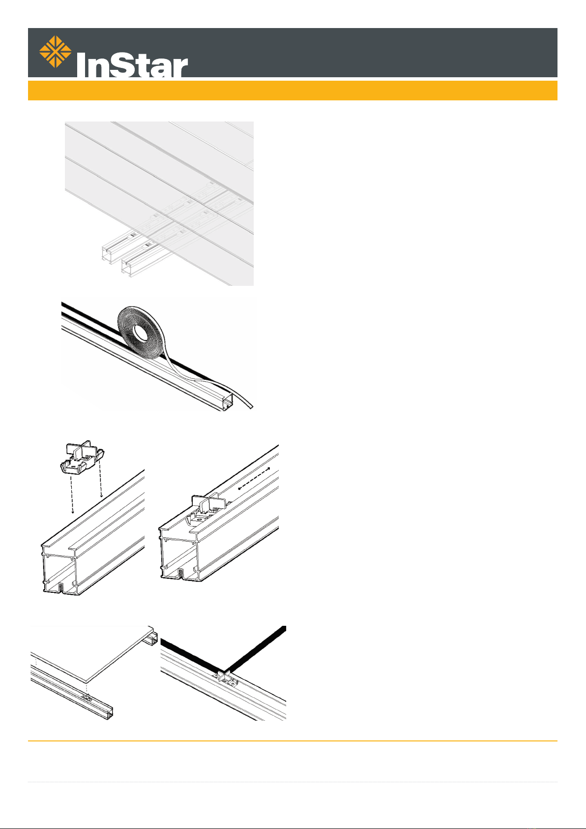
2. Assembling
• To assemble the frame, use the junction tab along with the
horizontal and vertical angle brackets.
• Tools: screwdriver and level.
• If the installation is longer than 3 metres, you can easily
connect two profiles - Connect the profile lengths using
junction tab and Profildeck screws.
• Place junction tab outside the profile.
• Pre-drill using the junction tab as a template.
• Pre-drill through holes using a 4 mm metal drill.
• Slide the 1st junction tab inside the profile and fix with 2 screws.
• Slide the 2nd junction tab inside the profile and fix with 2
screws.
• Ensure there is a 1 mm gap between the two profiles.
Using a horizontal junction angle bracket:
• To connect noggins.
• To create a U shape or L shape installation.
• Place horizontal junction bracket outside the profile.
• Fix with 2 screws using the slotted holes.
• Fix using a ProfilDeck® screw 4.8 x 19 mm tightened to a
torque of 2.5n. (The tightening torque is 8 on 20 for an 18 volts
screwdriver).
• Slide the 1st junction tab inside the profile and fix with 2 screws.
• Slide the 2nd junction tab inside the profile and fix with 2
screws.
• Ensure there is a 1 mm gap between the two profiles.
PFD
PROFILDECK ALUMINIUM SUB-FRAME SYSTEM
This information given in good faith and is based on the latest knowledge available to InStar UK Ltd. Whilst every eort has been made to ensure that the contents of the publication
are current while going to press, customers are advised that products, techniques and codes of practice are under constant review and liable to change without notice.
InStar UK Ltd, Holland House, Valley Way, Rockingham Road, Market Harborough, Leicestershire LE16 7PS | T: +44 (0)1858 456949 | E-mail: info@instar-uk.co.uk
Installation Guide Page 3
PFD
PROFILDECK ALUMINIUM SUB-FRAME SYSTEM
4. Finishing
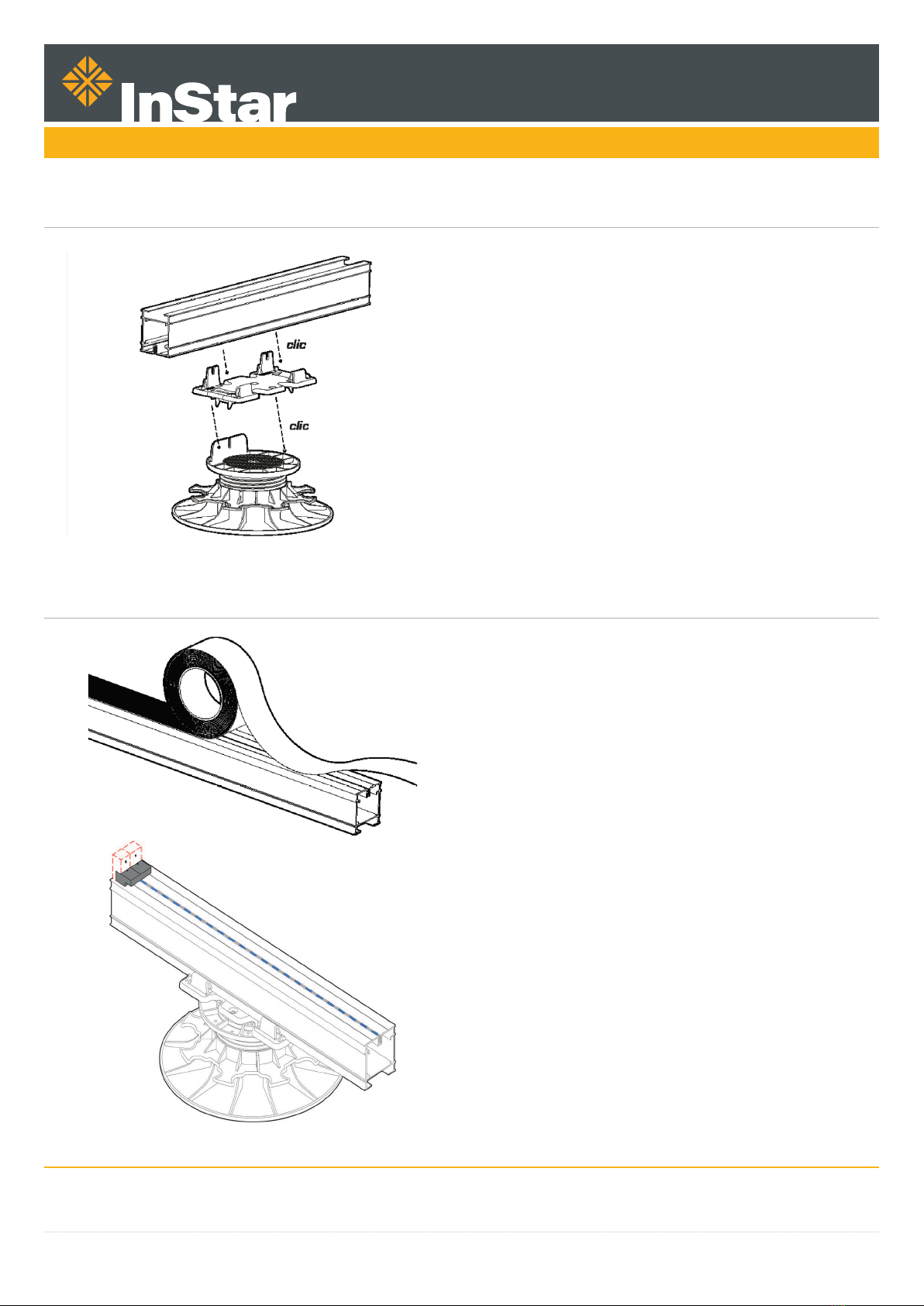
3. Pedestal Risers Installation
Place the pedestals on the marked positions on the ground.
• Clip the adaptor onto the top of the pedestal.
• Begin with the corner pedestals to level the sub-frame and
then lay and level the others.
- When laying parallel profiles always ensure there is a
pedestal underneath the connections points along with
pedestals at the recommended spacing.
- When installing with noggins lay the pedestal at the
recommended spacing.
• Clip the profile to the adaptor.
• Connect the adaptor to the profile using the two notches and
2 Profildeck screws. One fixing at each end of the length is
enough.
• Use the nut on the pedestal to simply adjust to the desired
height.
FOR DECKING:
• Lay the boards or the tiles according the defined pattern.
• Apply the decking cover tape on the decking side of the
aluminium profile (Ensure surface is clean and dry before
application). For best results, peel o the backing strip
progressively as you apply the tape.
• Lay the decking leaving a consistent space between the
boards. Fix using a 5.5 x 45 mm screw and tighten to max of
7n torque. (The tightening torque is 18 on 20 for an 18 volts
screwdriver).
• If using the invisible fixing system FixeGo®.
- Place a cleat at the end of each profile, the cleat should be at
the centre of the profile and positioned 5 mm in from the end.
- Pre drill with a 3 mm metal drill.
- The tightening torque is 10 on 20 for an 18 volts screwdriver.
- Fix the cleat with a 4 x 25 mm screw (supplied in Fixego kit).
This information given in good faith and is based on the latest knowledge available to InStar UK Ltd. Whilst every eort has been made to ensure that the contents of the publication
are current while going to press, customers are advised that products, techniques and codes of practice are under constant review and liable to change without notice.
InStar UK Ltd, Holland House, Valley Way, Rockingham Road, Market Harborough, Leicestershire LE16 7PS | T: +44 (0)1858 456949 | E-mail: info@instar-uk.co.uk
Installation Guide Page 4
- When butting up deck boards it is recommended to use two
noggins on the sub frame. One noggin to support the end of the
first deck board and the second to support the beginning of the
next.
- The 6 x 30 mm screws for Fixego are included in the Fixego kit.
- Pre-drill with a 4 mm metal drill.
- The tightening torque is 15 on 20 for an 18 volts screwdriver.
FOR PAVING:
• Apply the rubber tape on the paving side of the aluminium
profile (ensure surface is clean and dry before application).
For best results peel o the backing strip progressively as you
apply the tape.
• Insert the spacer on the paving side of the profile.
• For a staggered tile installation, the spacers can be easily split.
• Lay the tiles.
Click
PFD
PROFILDECK ALUMINIUM SUB-FRAME SYSTEM
This information given in good faith and is based on the latest knowledge available to InStar UK Ltd. Whilst every eort has been made to ensure that the contents of the publication
are current while going to press, customers are advised that products, techniques and codes of practice are under constant review and liable to change without notice.
InStar UK Ltd, Holland House, Valley Way, Rockingham Road, Market Harborough, Leicestershire LE16 7PS | T: +44 (0)1858 456949 | E-mail: info@instar-uk.co.uk
Installation Guide Page 5
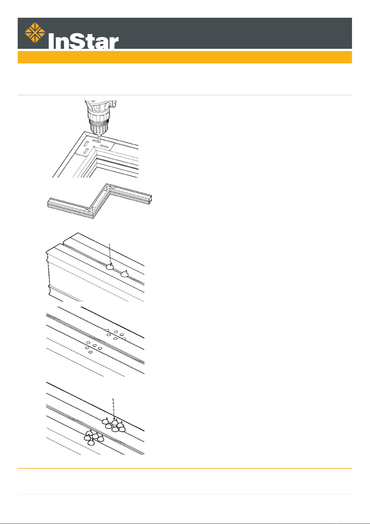
6. Additional Options
HOW TO CREATE A STEP
• Cut the profile at 45 degrees angle.
• Place a vertical junction angle bracket (outside the profile).
• Screw using the slotted holes and fix with the Profildeck® screw
4.8 x 19 mm.
HOW TO CREATE A STAIR RISER (2 OPTIONS):
On the decking side:
• Either, put some polyurethane glue on the central rail /
channel/ groove.
• Or, drill 5 holes with a 4 mm metal drill. Put some polyurethane
glue on the holes. Then, place the stair riser and press.
PU Glue
PU Glue
PFD
PROFILDECK ALUMINIUM SUB-FRAME SYSTEM
Table of contents


