manuals.online logo
Brands
  1. Home
  2. •
  3. Brands
  4. •
  5. INSTEON
  6. •
  7. Accessories
  8. •
  9. INSTEON 2420M User manual

INSTEON 2420M User manual

BEST LOCATIONS
Select a detector location that will provide the coverage required while
keeping in mind the following potential problems:
1.
Reflective surfaces - Do not aim the detector at reflective surfaces
such as mirrors or windows as this may distort the coverage pattern
or reflect sunlight directly onto the detector.
2.
Air flow - Avoid locations that are subject to direct high air flow such
as near an air duct outlet.
3.
Moisture - Do not place the detector near sources of steam or oil.
4.
Sunlight - Do not aim the detector such that it will receive direct or
reflected (mirror) sunlight.
5.
Obstruction - Do not limit the coverage with large objects within the
detection area such as plants or filing cabinets.
6.
Pet rejection - Do not aim the detector at a stairway which a pet has
access to and do not place furniture or objects higher than 3 ft./0.9
m, which a pet can climb onto (e.g. a cat on a couch), closer than
6 ft./1.8 m to the detector.
7.
Fireplace - Do not place the detector near a fireplace due to the light
and heat.
8.
Snow or ice – Snow or ice on the Fresnel lens may interfere with
Motion Sensor’s ability to detect motion.
9.
Dirt – Dirt on the Fresnel lens may interfere with Motion Sensor’s
ability to detect motion.
6. PLACEMENT TIPS
INSERT BATTERY
Use a small Phillips screwdriver to remo
ve screw and cover from battery
compartment on back of unit. Attach the included 9V battery. Do not
replace compartment cover until instructed to do so later in this manual.
Wait 5 minutes for the circuit to stabilize. Then, to confirm unit is
functioning,
tap the Set button a couple of times while watching the front of
the unit. Each time you tap the Set button, a red LED behind the sensor
lens will flash. Don’t worry if the LED flashes when you are not tapping the
Set button; it is simply indicating that
motion is being detected.
(Close-up
of battery
compartment)
ACCESS POINTS
Motion Sensor requires at least one INSTEON Access Point (#2443) or
other dual
-band product installed in your home. To confirm the Motion
Sensor is within RF range of your Access Point, have a friend watch the
LED on the side of your Access Point while you tap the Set button on the
Sensor (while holding it where you plan to install it). Access Point’s LED will
flash
a couple times every time you tap the Set button if it is within range.
Indoor/Outdoor
INSTEON™ Motion Sensor Model #2420M
1. INTRODUCTION
The INSTEON Motion Sensor is an indoor/outdoor motion sensor that will
turn INSTEON
-controlled lights on and off i
n response to movement around
your home. The sensor also contains a photocell, allowing you to configure
the unit to only turn your lights on at night. Pair the Motion Sensor with
INSTEON software for almost limitless automation possibilities.
In this pac
kage you will find the Motion Sensor, a 9V battery, a swivel
mount and 2 screws.
Motion Sensor
9V
Battery
Swivel
Mount
2- 3x18
Screws
3. SETUP
4. SETUP INSTEON DEVICE CONTROL
LINKING TO INSTEON RESPONDERS
1.
Press and hold the Set button on Motion Sensor for 5 seconds (until red
LED behind sensor lens begins steady blinking). You now have 4
minutes to complete step 2.
2.
Press and hold the Set button1on the INSTEON responder (e.g.
SwitchLinc™) you would like the Motion Sensor to control for 5 seconds
(an LED may blink and the connected load/bulb may flash).
3.
The Motion Sensor LED will stop blinking (if not, try step 2 again).
4.
Test by tapping the Set button on Motion Sensor. Each tap should
alternatively turn the device you linked (e.g., SwitchLinc) on and off.
(The Motion Sensor LED will flash each time the Set button is tapped.)
5.
Repeat this procedure for up to 32 responders you wish Motion Sensor
to control.
1
For multi-button responders (e.g., KeypadLinc™), tap the button you wish
to control before pressing and holding its Set button.
8. ADJUST DETECTION AREA
AIMING and SENSITIVITY
1. Tap the Set button on Motion Sensor until the linked responder(s) turn
off.
2. Within 10 seconds walk well out of detection area.
3. Wait 20 seconds.
4. Walk into and near your detection area. Your linked responders will
turn on (LED will flash upon initial motion, then once every 8 seconds
during motion).
a. If LED does not flash while you are moving within the
desired detection area, re-aim Sensor (usually means
pointing the Sensor “up”).
b. If LED flashes while you’re moving outside detection area:
i. Aim Sensor to decrease range (usually means
aiming the Sensor “down”).
ii. If aiming sensor does not generate desired results
place jumper 1 on both pins (see section Setup
Modes).
Set
button
2. OPERATION
WHEN MOTION IS SENSED
1. When motion is sensed the Motion Sensor will send an ON command
to up to 30 linked INSTEON responders and flash its LED (unless it is
daytime and unit is in night-only mode).
2. Sensor will begin its automatic countdown.
3. Whenever motion is sensed during countdown, the countdown will be
reset to easily allow you to create “occupied” versus “unoccupied”
modes for your home.
4. When countdown expires the Sensor will send an OFF command to
all linked responders (unless it is in on-only mode).
APPLICATIONS
1. Turn on driveway or front step lights when visitors approach.
2. Have your fountain always on when you are around (and off when
you are away).
3. Save money by having HVAC and lighting automatically go into
energy-saving mode when no one is around.
MOUNTING (See Locating Tips for Help)
1.
Use the two small screws (included) to secure the swivel mounting
bracket at your desired location.
2.
Slide Motion Sensor onto the swivel mounting bracket (sliding the unit
to the right) until you hear a click.
3.
Aim Motion Sensor towards the area in which you wish to detect motion
(detection area).
4.
Test by walking through the area. Linked responders should turn on
when motion is sensed, and off 1 minute after last motion sensed.
7. MOUNT SENSOR
5. DETECTING AREA
11. TROUBLESHOOTING
Symptom
Resolution
Sensor won’t link to
responders
Move a dual-band INSTEON device (e.g.,
Access Point) closer to the Motion Sensor
Sensor won’t
control linked
responders
a) Make sure LED flashes to confirm it has
power and is sensing motion
b) Sensor is in night-only mode (and it is “day”)
c) Move a dual-band INSTEON device (e.g.,
Access Point) closer to the Motion Sensor
d) Sensor is in its 1 minute countdown
LED flashing rapidly
after motion is
detected
Sensor did not receive an acknowledgement
from one or more linked devices. If this occurs
repeatedly you may need to move a dual-band
INSTEON device closer to the Sensor or you
may need to unlink a device which is no longer
in use in your home. If the INSTEON
responders are no longer available, you may
either use a software application or perform a
factory reset to remove the unwanted links.
LED not flashing
upon motion.
a) You may need to wait up to 8 seconds to
see the flash
b) Battery may need to be replaced
Not sensing motion
a) Light detected and unit is in night-only mode
b) Motion Sensor aimed too low
c) Temperature too high, or low (sensor needs
to be able to distinguish between what is
being sensed and its surroundings
d) See Placement Tips section
LED is double
flashing upon
motion
Low battery warning—replace with fresh battery
TECHNICAL SUPPORT
Skylink has contracted with INSTEON for support of the INSTEON Motion
Sensor. Customers should contact INSTEON for technical support.
1.
Call INSTEON Support Line at 800-762-7845
2. Visit
www.insteon.com
Search for d
ual-band INSTEON products:
http://www.smarthome.com/dualband
12. REMOVE CONTROL OF INSTEON
UNLINKING FROM INSTEON RESPONDERS
1. Press and hold the Set button on Motion Sensor for 5 seconds (until
red LED behind sensor lens begins blinking).
2. Press and hold the Set button on Motion Sensor for another 5
seconds (until the LED changes its blink pattern – it will now be on
longer than off).
3. Press and hold the Set button on the INSTEON responder you
would like to unlink (until its LED blinks).
4. The Motion Sensor LED will stop blinking (if not, try step 3 again).
5. Test by tapping the Set button on Motion Sensor. Taps should no
longer control the Unlinked device.
14. FCC
RETURN UNIT TO FACTORY SETTINGS
1. If possible, unlink from all responders before proceeding.
2. Remove battery.
3. Wait 15 seconds.
4. While pressing and holding the Set button, reattach the battery and
continue holding the Set button.
5. After around 2 seconds, the LED will turn on. Keep pressing the Set
Button for 5 seconds and then release the Set Button. The LED will
turn off after about 2 seconds.
13. FACTORY RESET
P/N. 2420M Rev. 06
-07-2012
©2009 SKYLINK GROUP
FCC
This device co
mplies with FCC Rules and Industry Canada license-
exempt
RSS standard(s). Operation is subject to the following two conditions: (1)
this device may not cause harmful interference, and (2) this device must
accept any interference, including interference tha
t may cause undesired
operation of the device.
Le present appareil
est conforme aux CNR d'Industrie Canada applicables
aux appareils radio exempts de licence. L'exploitation est autorise aux
deux conditions suivantes: (1) l'appareil ne doit pas produire de brouillage,
et (2) l'utilisateur de l'appareil doit accepter tout
brouillage radiolectrique
subi, mme si le brouillage est susceptible d'en compromettre le
fonctionnement.
WARNING
Changes or modifications to this unit void the user’s authority to operate
this produ
ct and the manufacturer’s warranty.
10. ADJUST MODES
ADJUST DIALS
Left Dial
– Adjust Automatic “Off” Countdown
Using a small Phillips screwdriver, adjust to the desired time duration in
which you want Motion Sensor to send an OFF command after the last
motion sensed. Turning the dial all the way counter
-clockwise sets the
countdown to 30 seconds; tur
ning the dial all the way clockwise sets it to
2 hours. Anywhere in between results in a proportional difference
between 30 seconds and 2 hours.
Right Dial
– Day/Night Threshold
Using a small Phillips screwdriver, adjust the day/night threshold to
desired
light level. Turning the dial clockwise increases the light level of
the threshold; turning the dial counter
-clockwise decreases the light level
of the threshold. For example, when you turn the dial all the way
clockwise, Motion Sensor will read “night” no
matter how bright it is.
Likewise, turning the dial all the way counter
-clockwise will make Motion
Sensor read “day” no matter how dark it is. Turning the dial anywhere in
between will choose the specific light level which Motion Sensor uses to
determine
“night” vs. “day.” To test, set Motion Sensor to night-only mode
(see above) and tap the Set button 7 times. If it reads the current light
level as “night,” it will turn on its linked responders on first sensed motion.
If it reads “day,” the LED will flash
on first motion, but it will not turn on its
linked responders.
9. SETUP MODES (OPTIONAL)
and activate motion to establish the new setting.
Jumper 2
– Disable LED
If you wish to disable the LED (will still operate during setup), install
Jumper 2 on both pins. Tap the Set button
once, wait 10 seconds and
activate motion to establish the new setting.
Jumper 3
– Night-Only Mode
If you wish to have the Sensor operate only when dark, install Jumper 3
on both pins. Tap the Set button once, wait 10 seconds and activate
motion to estab
lish the new setting. Note: It takes 3.5 minutes (or 7 Set
button taps) to detect the difference between day and night. See
Day/Night Threshold
below for details.
Jumper 4
– On-Only Mode
If you wish to disable the automatic countdown “Off”, install jumper
4 on
both pins and the Motion Sensor will only send “On”. Tap the Set button
once, wait 10 seconds, and activate motion to establish the new setting.
Jumper 5
– Remote (Software) Management
If you wish to manage all of Motion Sensor’s settings via INSTEON
software (such as HouseLinc 2), install jumper 5 on both pins. Then, press
and hold the Set button on Motion Sensor to put the unit in linking mode
and allow the INSTEON software to access its settings.
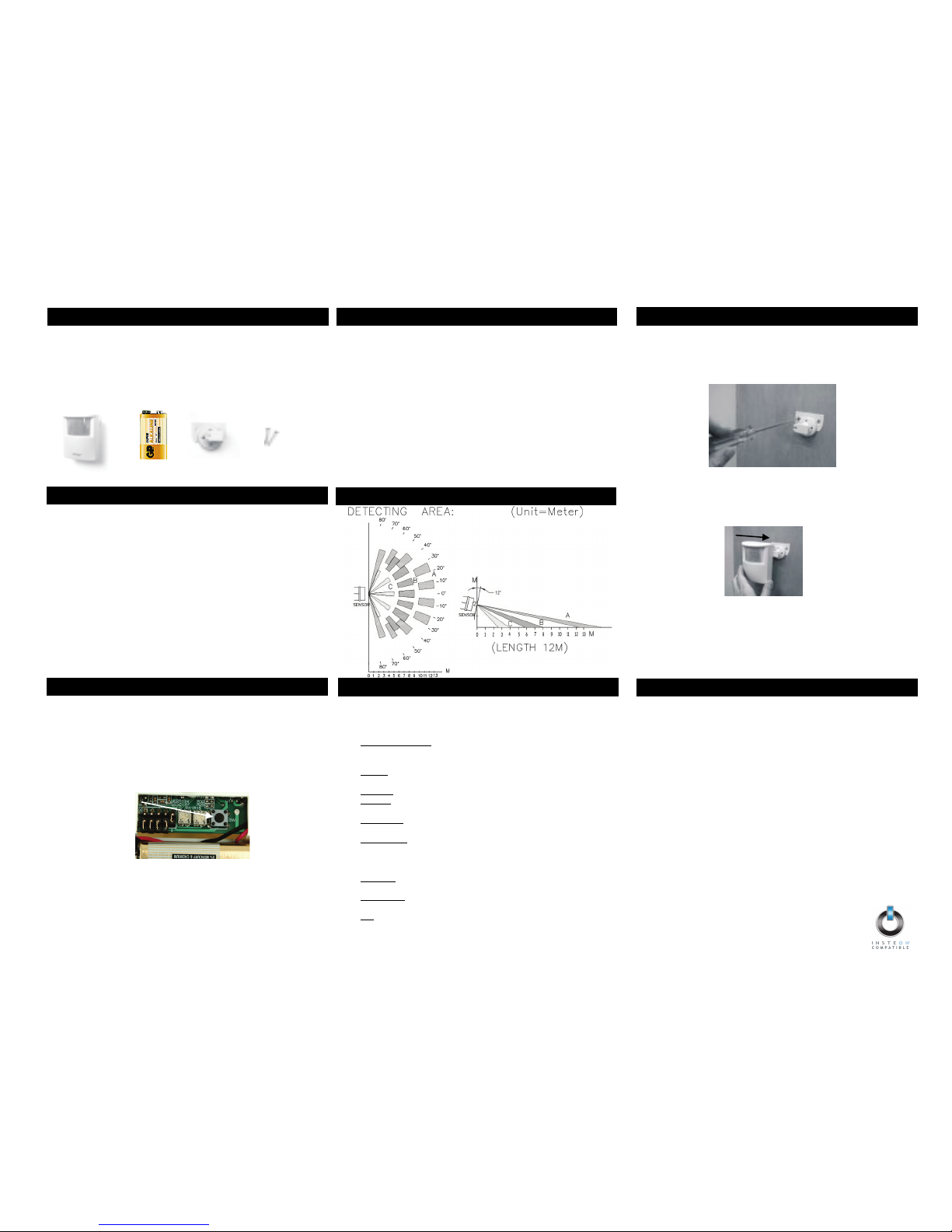
Jumper 1
Jumper 2
Jumper 3
Jumper 4
Jumper 5
Automatic Off Countdown
Day/Night Threshold
Set button
SET JUMPERS
Jumpers are small p
lastic
“boxes” that act as a switch.
When installed on 2 pins,
the switch is “on.” When
installed on 1 pin (or
missing), the switch is “off.”
Jumper 1
– Sensitivity
To reduce Sensor’s
detection range by
approximately 33%, use
needle
-nose pliers to
car
efully remove Jumper 1
(the left
-most jumper) from
the single pin it is installed
on and reinstall it on both
pins. Tap the Set button
once, wait 10 seconds
15. CUSTOMER SERVICE

Other INSTEON Accessories manuals

INSTEON OutletLinc 2472D User manual

INSTEON

INSTEON OutletLinc 2472D User manual

INSTEON 2845-222 US User manual

INSTEON

INSTEON 2845-222 US User manual

INSTEON 2842-222 User manual

INSTEON

INSTEON 2842-222 User manual

INSTEON 2421-222 User manual

INSTEON

INSTEON 2421-222 User manual

INSTEON 2845-x22 User manual

INSTEON

INSTEON 2845-x22 User manual

INSTEON 2844-222 User manual

INSTEON

INSTEON 2844-222 User manual

INSTEON TriggerLinc 2843-2 User manual

INSTEON

INSTEON TriggerLinc 2843-2 User manual

INSTEON 2845 22 Series User manual

INSTEON

INSTEON 2845 22 Series User manual

INSTEON 2843-222 User manual

INSTEON

INSTEON 2843-222 User manual

INSTEON 2663-222 User manual

INSTEON

INSTEON 2663-222 User manual

Popular Accessories manuals by other brands

Takuma e-Foil user guide

Takuma

Takuma e-Foil user guide

ergobaby Metro user manual

ergobaby

ergobaby Metro user manual

Byron SX-15i Installation and operation instruction

Byron

Byron SX-15i Installation and operation instruction

ring VIDEO DOORBELL user guide

ring

ring VIDEO DOORBELL user guide

Vetek VB2-10K manual

Vetek

Vetek VB2-10K manual

EMRI LX10.1 manual

EMRI

EMRI LX10.1 manual

OUTXE PCPB10000WS user manual

OUTXE

OUTXE PCPB10000WS user manual

Zte ZXMBW E9230 user manual

Zte

Zte ZXMBW E9230 user manual

HP Workstation x1000 supplementary guide

HP

HP Workstation x1000 supplementary guide

Hubbell BTSMP-HMO Installation and operation instructions

Hubbell

Hubbell BTSMP-HMO Installation and operation instructions

NHR S05-SM user manual

NHR

NHR S05-SM user manual

Johnson Controls NS Series installation guide

Johnson Controls

Johnson Controls NS Series installation guide

SunSetter 900XT Replacement

SunSetter

SunSetter 900XT Replacement

Stiga King Size GT instruction manual

Stiga

Stiga King Size GT instruction manual

Carrier 50LJ900185 installation instructions

Carrier

Carrier 50LJ900185 installation instructions

Omron EE-SX47 - datasheet

Omron

Omron EE-SX47 - datasheet

HQ EL-PIR80 manual

HQ

HQ EL-PIR80 manual

PCB Piezotronics IMI SENSORS 641B61 Installation and operating manual

PCB Piezotronics

PCB Piezotronics IMI SENSORS 641B61 Installation and operating manual

manuals.online logo
manuals.online logoBrands
  • About & Mission
  • Contact us
  • Privacy Policy
  • Terms and Conditions

Copyright 2025 Manuals.Online. All Rights Reserved.