Instinct 35804000 User manual

812-482-2932
www.ridetech.com
Table of contents
Page 2......... Included components
Page 3......... ECU Installation
Page 4......... GSensor Installation
Page 5......... Sensors Installation
Page 6......... Mode Switch Operation & Launch Control
Pages 7-9..... Drive By Wire TPS Calibration
Installation
Instructions
Installation
Instructions
Part # 35804000 - Instinct Shock Controller
Instinct Shock Controller
Installation Instructions

Installation
Instructions
812-482-2932
www.ridetech.com
Installation
Instructions
Major Components .....In the box
Item
#Part # Description QTY
1 35800001 ECU 1
2 35800002 Main Harness 1
3 35800003 GSensor 1
4 Mode Select Harness - Included in Main Harness 1
5 GSensor Extension Harness - Included in Main Harness 1
6 35900011 Brake Pressure Sensor Harness 1
7 35900012 Speed Sensor Harness 1
2
6
2
3
4
5
1
7

Installation
Instructions
Installation
Instructions
3
812-482-2932
www.ridetech.com
Instinct ECU Installation
8.
1. First lay out the harness in the vehicle with the main ECU connector located at the rear, typically in the trunk
on the seat back support or under the package tray. Ensuring there is enough wire length to adequately reach the
shocks at each corner.
2. Locate a suitable location to mount the ECU. On the seat back support or under the package tray are popular
options.
3. Mark and drill two holes and utilize the appropriate mounting hardware for your installation to secure the ECU
enclosure.
4. Plug in the wire harness and begin routing wire through the vehicle.
s4HESHOCKSATEACHCORNERHAVEADEDICATEDCONNECTORWITHALABEL
s4HE'3ENSORCOMMUNICATIONWIRESSHOULDBERUNDOWNTHECENTEROFTHEVEHICLE4HE%XTENSION(ARNESSSUP
plied will plug into the GSensor and the Main Harness.
s4HE-ODE3ELECTOR3WITCHPLUGSINTOTHEHARNESSTHATRUNSWITHTHE&RONT3HOCK(ARNESS
ECU Connector
Mode Selector Switch
(brown, female, 4 wires)
Communication to GSensor
(brown, male, 4 wires)
use supplied extension harness
Green/Yellow Twisted = CAN
Shock Connectors
Brown and Black = Ground
Red = +12V at Battery
Orange = +12V at Battery
Yellow = +12V Switched Ignition
{

Installation
Instructions
Installation
Instructions
GSensor Installation
812-482-2932
www.ridetech.com
4
5.4HE'3ENSORSHOULDBEMOUNTEDLOWANDASCLOSETOTHECENTEROFTHEVEHICLEASPOSSIBLE4YPICALLY
THISMEANSONTHETRANSMISSIONTUNNELORCENTERCONSOLEJUSTUNDERTHEDASHAREA4HISPROVIDESASECURE
location with easy access to the wiring.
sThe sensor should be mounted as level with the ground as possible, with the mounting
flanges on the bottom (like it was sitting on a table), with the wires protruding pointing to the
rear of the vehicle.
s(OOKAND,OOPFASTENER6ELCROISTHEPREFERREDMOUNTINGMETHODASITSQUICKEASYREMOVABLEAND
the GSensor prefers slight vibration isolation from the vehicle.
s9OUWILLNEEDTOACCESSTHE0ROGRAMMING"UTTONONTHE'3ENSORWHENCALIBRATINGVEHICLESPEEDSOIT
NEEDSTOBEACCESSIBLEATLEASTONCEAFTERINSTALLATIONYOUCANHAVEITHIDDENSOLONGASYOUPULLITOUT
TOLEARNVEHICLESPEEDTHENHIDEITONCEAGAIN
s0LUGINEACHSENSORASILLUSTRATEDINTHEIMAGEABOVE
6. Install the Mode Selector Switch by locating a suitable mounting location, within the drivers reach
while belted into the car. Drill a ½” hole and insert the Mode Selector Switch connector first into the
hole.
s2OUTETHE-ODE3ELECTOR3WITCHWIRE(Brown Female Plug, 4 wire) from the main harness to the
-ODE3ELECTORANDPLUGINSEESTEP
LED IndicatorProgramming Button
Communication
to ECU
(long pigtail)
(brown, female)
(4 wires)
Brake Pressure
Sensor
BLACKMALEWIRES
YELLOWWIRE
NOT USED
BROWNFEMALEWIRES
Speed
Sensor
(black, female, 2 wires)
Throttle Position
Sensor
(black, female, 3 wires)
(blue wire)
Front of Vehicle

Installation
Instructions
Installation
Instructions
5
812-482-2932
www.ridetech.com
Instinct Sensor Installation
7. Install the Sensors:
7a. Brake Pressure Sensor (Black Male Plug - 4 wire - yellow wire - short pigtail)
s4HE"RAKE0RESSURE3ENSORSHOULDBEINSTALLEDINTHEFRONTBRAKECIRCUIT4YPICALLYTHEEASIESTMOSTCON
VENIENTLOCATIONISDIRECTLYOFFTHEMASTERCYLINDERUSINGAh4vlTTING
s2OUTETHEWIREHARNESSTOTHE'3ENSORANDPLUGITINASINDICATEDINTHEIMAGEABOVE
7b. Throttle Position Sensor (Black Female Plug - 3 wire - blue wire - short pigtail)
s)NSTALLATIONOFTHE403SENSORDEPENDSONYOURAPPLICATION)FYOUAREUSINGADRIVEBYWIRE'-,3
3ERIESOR&ORD#OYOTEITISASSIMPLEASUNPLUGGINGTHETHROTTLEPEDALANDPLUGGINGINTHE2IDETECH403
adapter harness.
s)FYOUAREUTILIZINGADIFFERENTFUELINJECTEDMOTORYOUWILLNEEDTOUTILIZETHE5NIVERSAL2IDETECH403
HARNESSCONNECTINGTHEBLACKWIRETOTHEGROUNDATTHE/%403SENSORANDTHEREDWIRETOTHE6
SIGNALWIREOFTHE/%403SENSOR0LEASEREFERENCEYOURPARTICULARAPPLICATIONSWIRINGDOCUMENTATIONFOR
proper connections.
s)FYOUARERUNNINGACARBURETORYOUWILLNEEDTOSOURCEA403KITTHATlTSYOURPARTICULARCARBANDUTI
LIZETHE5NIVERSAL2IDETECH403HARNESSTOPLUGITINTOTHE'3ENSOR
Whichever option you have, route the wire harness to the GSensor and plug it in as indicated in the im-
age above.
7c. Vehicle Speed Sensor (Black Female Plug - 2 wire - short pigtail)
s#ONNECTTHE2IDETECH6EHICLE3PEED3ENSORHARNESSTOANYPULSEGENERATINGSPEEDSIGNAL4HISCOULD
be the OE sensor in the tail shaft of the transmission, or an aftermarket inductive sensor located on a
WHEELORDRIVESHAFT3PLICETHEWIRESINTOTHEWIRESFORTHE3PEED3ENSORPOLARITYISNTCRITICAL
sWhichever option you choose, route the wire harness to the GSensor and plug it in as indicated in the
image above.
SETTING THE VEHICLE SPEED IS NECESSARY FOR PROPER OPERATION!
Setting Vehicle Speed
1- Push and hold the purple Program button on the GSensor
-the LED will turn orange
2- Push and hold the purple Program button on the GSensor again
THE,%$WILLmASHWITHTHESPEEDOFTHEVEHICLESOIFYOUARESITTINGSTILLIT7),,./4mASHUNTIL
THEVEHICLESTARTSMOVING
3- Once the vehicle is traveling 40mph, press the purple Programming button once more
-the LED will turn solid orange, then turn off
4- Cycle the power, including the USB if you have it plugged in
5-9OUCANNOWVERIFYTHESPEEDSENSORWASLEARNEDCORRECTLYBYCHECKINGYOURSPEEDINTHE$3#SOFT
ware

Installation
Instructions
Installation
Instructions
Mode Switch Operation & Launch Control
812-482-2932
www.ridetech.com 6
4HE-ODE3WITCHISUSEDTOTURNTHESYSTEMONANDISUSEDTOSELECTWHICHMODETHESYSTEMISIN4HE
Mode Switch has a Green LED to help identify which mode the system is in.
Initially the system is off, LED will be off. Each time you press the button it toggles to the next
mode.
-LED off - Normal Mode
-One Press - LED Solid - Sport Mode
-2nd Press - LED Flashing - Track Mode
-Press again and the system turns off, returns to Street Mode
Launch Control:
The Instinct system is equipped with and automated Launch Control feature.
Launch Control is activated when:
BRAKEPRESSUREOVERTHESETTINGINTHEBRAKETABLEDEFAULTSETTINGISBAR
-mph less than or equal to zero
THROTTLEBEYONDTHESETTINGINTHEACCELTABLEDEFAULTSETTINGIS
When Launch Control is active the Mode Selector button will flash rapidly.
IF YOU ARE USING A DRIVE BY WIRE ENGINE, THE SYSTEMS THROTTLE POSITION PARAMETERS
MUST BE RECALIBRATED. PAGES 7-9 DEMONSTRATES THE PROPER PROCEDURE TO RECALI-
BRATE THE THROTTLE POSITION SENSOR PARAMETERS.

Installation
Instructions
Installation
Instructions
Drive By Wire Throttle Position Sensor Calibration
7
812-482-2932
www.ridetech.com
1 /NCE YOU HAVE THE $3# 4UNER SOFT
WAREOPEN3ELECTTHEh4OOLSvDROPDOWN
from the top of the screen.
23ELECTh4EST3ERIAL0ORTv
-4HEh3ERIAL0ORT4ESTERvBOXAPPEARS
3. Hit the “Start” button.
-4HEh7RITE/UTvBOXISNOWACTIVE
4. With the throttle pedal in the idle po-
sition, type AB in the “Write Out” box.
***Must be capital letters***
1.
4.
3.

Installation
Instructions
812-482-2932
www.ridetech.com
Installation
Instructions
8
TPS Calibration
5. Hit “Send” or press the “Enter” but-
ton on your keyboard
-h!"4HROTTLE#LOSED9.vWILL
BEDISPLAYEDINTHEh2EAD)NvBOXTOTHE
right.
6. 4YPETHELETTERY
***Must be capital letters***
-h3AVED4HROTTLE#LOSEDSETTINGvWILL
BEDISPLAYEDINTHEh2EAD)NvBOXTOTHE
right with the value that has been saved.
7. Depress the throttle pedal to Wide
/PEN4HROTTLE7/4
8. While holding the pedal to the floor,
type AC in the “Write Out” box.
5.
7.
6.

Installation
Instructions
Installation
Instructions
9
812-482-2932
www.ridetech.com
9. Hit “Send” or press the “Enter” but-
ton on your keyboard.
h!#4HROTTLE7/49.vWILL
BEDISPLAYEDINTHEh2EAD)NvBOXTOTHE
right.
10.4YPETHELETTER Y
***Must be capital letters***
h3AVED4HROTTLE7/4vWILLBEDIS
PLAYEDINTHEh2EAD)NvBOXTOTHERIGHT
with the value that has been saved.
11. 9OU MAY NOW RELEASE THE THROTTLE
PEDALFROMTHE7/4POSITIONRETURNING
back to the idle position.
12. Hit the “Clear” button to clear the
h2EAD)NvBOX
13. Hit the “Stop” button to stop com-
municating with the ECU.
14. Hit the “OK” button to exit the Serial
0ORT4ESTERBOX
-you will be returned to the main
$3#4UNERSOFTWARESCREEN
9.
11.
10.
TPS Calibration
Table of contents
Popular Controllers manuals by other brands
ABB
ABB ACS880-01 Series Quick installation guide
Johnson Controls
Johnson Controls SMART EQUIPMENT VERASYS VEC100 quick start guide
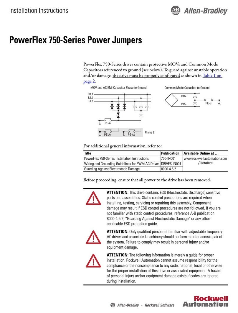
Allen-Bradley
Allen-Bradley PowerFlex 750 Series installation instructions

Black Stone
Black Stone BL 931700-0 instruction manual
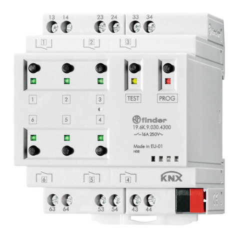
finder
finder 19 Series manual
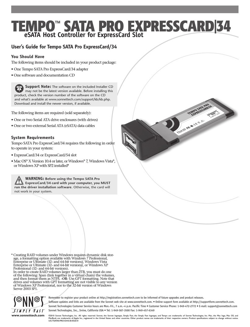
Sonnet
Sonnet TEMPO SATA PRO EXPRESSCARD/34 user guide
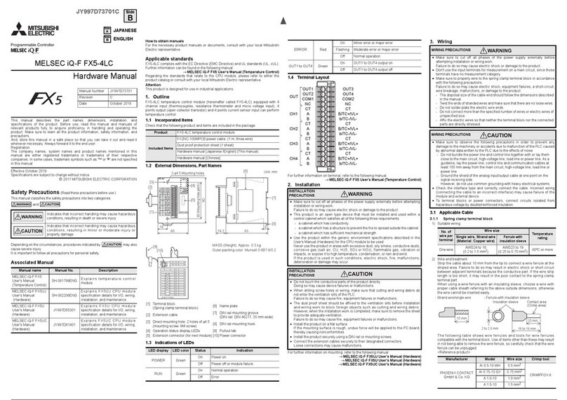
Mitsubishi Electric
Mitsubishi Electric FX5 MELSEC iQ-F FX5-4LC Hardware manual
elobau
elobau eloFlex 470EFR operating instructions
Eliwell
Eliwell EWPlus 971 manual
Master
Master WiSlide 500 KG User and installation manual
Allen-Bradley
Allen-Bradley CompactLogix 5480 user manual
Rain Bird
Rain Bird E-6C Manual for use


