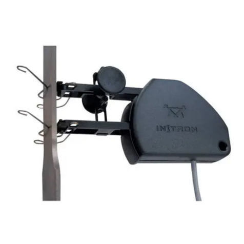
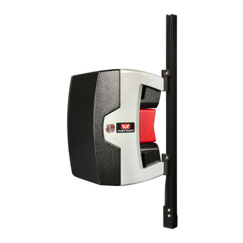
Instron 2620-600 Series User manual

2620-600 Series
Dynamic Strain Gauge
Extensometers
Reference Manual - Equipment
M26-16655-EN Revision A
The difference is measurable ®

Electromagnetic Compatibility
Whereapplicable,thisequipmentisdesignedto
complywithInternationalElectromagnetic
Compatibility(EMC)standards.
ToensurereproductionofthisEMCperformance,
connectthisequipmenttoalowimpedanceground
connection.Typicalsuitableconnectionsareaground
spikeorthesteelframeofabuilding.
Proprietary Rights Notice
Thisdocumentandtheinformationthatitcontainsare
thepropertyofIllinoisToolWorksInc.(ITW).Rights
toduplicateorotherwisecopythisdocumentand
rightstodisclosethedocumentandtheinformation
thatitcontainstoothersandtherighttousethe
informationcontainedthereinmaybeacquiredonly
bywrittenpermissionsignedbyadulyauthorized
officerofITW.
Trademarks
Instron®isaregisteredtrademarkofIllinoisTool
WorksInc.(ITW).Othernames,logos,iconsandmarks
identifyingInstronproductsandservicesreferenced
hereinaretrademarksofITWandmaynotbeused
withoutthepriorwrittenpermissionofITW.
Otherproductandcompanynamesusedhereinare
trademarksortradenamesoftheirrespective
companies.
© Copyright 2012 Illinois Tool Works Inc.
All rights reserved.
All of the specifications shown in this document
are subject to change without notice.
Original language
Product Support: www.instron.com

Preliminary Pages
iii
Product Support: www.instron.com
General Safety Precautions
Materials testing systems are potentially hazardous.
Materials testing involves inherent hazards from
high forces, rapid motions, and stored energy. You
must be aware of all moving and operating
components in the testing system that are
potentially hazardous, particularly force actuators
or a moving crosshead.
Before operating the system, ensure you gain a
thorough understanding of the equipment by:
•receiving training on the safe operation of the
system.
•reading and understanding the general hazards
associated with materials testing systems as
detailed on pages iv to vii.
•carefully reading all relevant manuals and
observing all Warnings and Cautions. The term
Warning is used where a hazard may lead to
injury or death. The term Caution is used where
a hazard may lead to damage to equipment or
to loss of data.
•carrying out your own safety risk assessment
on the use of the test system, test methods
employed, specimen loading and specimen
behavior at failure.

Preliminary Pages
iv M26-16655-EN
General Safety Precautions
Instron products, to the best of its knowledge,
comply with various national and international
safety standards, in as much as they apply to
materials and structural testing. We certify that our
products comply with all relevant EU directives
(CE mark).
Because of the wide range of applications with
which our instruments are used, and over which we
have no control, additional protection devices and
operating procedures may be necessary due to
specific accident prevention regulations, safety
regulations, further EEA directives or locally valid
regulations. The extent of our delivery regarding
protective devices is defined in your initial sales
quotation. We are thus free of liability in this
respect.
At your request, we will gladly provide advice and
quotations for additional safety devices such as
protective shielding, warning signs or methods of
restricting access to the equipment.

Preliminary Pages
v
Product Support: www.instron.com
Warnings
Crush Hazard - Take care when installing or
removing gauges, extensometers,
specimens, assemblies, structures, or load
string components.
Installation or removal of gauges, extensometers,
specimens, assemblies, structures, or load string
components involves working inside the hazardous
area between the grips or fixtures. Keep clear of the
jaws of a grip or fixture at all times. Keep clear of
the hazard area between the grips or fixtures during
actuator or crosshead movement. Ensure that all
actuator or crosshead movements necessary for
installation or removal are slow and, where
possible, at a low force setting.
Hazard - Press the Emergency Stop button
whenever you consider that an unsafe
condition exists.
The Emergency Stop button removes hydraulic
power or electrical drive from the testing system
and brings the hazardous elements of the system to
a stop as quickly as possible. It does not isolate the
system from electrical power, other means are
provided to disconnect the electrical supply.
Whenever you consider that safety may be
compromised, stop the test using the Emergency
Stop button. Investigate and resolve the situation
that caused the use of the Emergency Stop button
before you reset it.

Preliminary Pages
vi M26-16655-EN
Flying Debris Hazard - Wear eye protection
and use protective shields or screens
whenever any possibility exists of a hazard
from the failure of a specimen, assembly or
structure under test.
Wear eye protection and use protective shields or
screens whenever a risk of injury to operators and
observers exists from the failure of a test specimen,
assembly or structure, particularly where explosive
disintegration may occur. Due to the wide range of
specimen materials, assemblies or structures that
may be tested, any hazard resulting from the failure
of a test specimen, assembly or structure is entirely
the responsibility of the owner and the user of the
equipment.
Hazard - Protect electrical cables from
damage and inadvertent disconnection.
The loss of controlling and feedback signals
that can result from a disconnected or
damaged cable causes an open loop condition
that may drive the actuator or crosshead
rapidly to its extremes of motion. Protect all
electrical cables, particularly transducer
cables, from damage. Never route cables
across the floor without protection, nor
suspend cables overhead under excessive
strain. Use padding to avoid chafing where
cables are routed around corners or through
wall openings.
Warnings

Preliminary Pages
vii
Product Support: www.instron.com
High/Low Temperature Hazard - Wear
protective clothing when handling
equipment at extremes of temperature.
Materials testing is often carried out at non-
ambient temperatures using ovens, furnaces
or cryogenic chambers. Extreme temperature
means an operating temperature exceeding 60
°C (140 °F) or below 0 °C (32 °F). You must
use protective clothing, such as gloves, when
handling equipment at these temperatures.
Display a warning notice concerning low or
high temperature operation whenever
temperature control equipment is in use. You
should note that the hazard from extreme
temperature can extend beyond the immediate
area of the test.
Electrical Hazard - Disconnect the
electrical power supply before removing
the covers to electrical equipment.
Disconnect equipment from the electrical
power supply before removing any electrical
safety covers or replacing fuses. Do not
reconnect the power source while the covers
are removed. Refit covers as soon as possible.
Warnings

Preliminary Pages
viii M26-16655-EN

Preliminary Pages
ix
Product Support: www.instron.com
Table of Contents
Chapter 1 Introduction . . . . . . . . . . . . . . . . . 1-1
General Description . . . . . . . . . . . . . . . . . . 1-1
Chapter 2 Operation . . . . . . . . . . . . . . . . . . . 2-1
Handling Precautions . . . . . . . . . . . . . . . . . 2-1
Preparing for Use . . . . . . . . . . . . . . . . . . . . 2-3
Mounting the Extensometer . . . . . . . . . . . . 2-5
Calibration . . . . . . . . . . . . . . . . . . . . . . . . 2-11
Electrical Calibration . . . . . . . . . . . . . . 2-12
Manual Calibration . . . . . . . . . . . . . . . 2-13
Temperature Calibration . . . . . . . . . . . 2-13
Chapter 3 Maintenance . . . . . . . . . . . . . . . . 3-1
Routine Maintenance . . . . . . . . . . . . . . . . . 3-1
Replacement Parts. . . . . . . . . . . . . . . . . . . 3-2
Appendix A Specification . . . . . . . . . . . . . . . . A-1
General . . . . . . . . . . . . . . . . . . . . . . . . . . A-1
Compatibility . . . . . . . . . . . . . . . . . . . . A-3
2620-601 . . . . . . . . . . . . . . . . . . . . . . . A-4
2620-602 . . . . . . . . . . . . . . . . . . . . . . . A-4
2620-603 . . . . . . . . . . . . . . . . . . . . . . . A-5
2620-604 . . . . . . . . . . . . . . . . . . . . . . . A-5

Preliminary Pages
xmM26-16655-EN

1-1
Chapter 1
Introduction
General Description
Instron Dynamic Strain Gauge
Extensometers are accurate, lightweight
strain gauge units used for accurate direct
measurement and closed-loop control of
strain in cyclic high frequency materials
testing applications. Tensile, compressive,
low and high cycle fatigue testing as well as
straight line (ramp) testing may be performed
with these devices.
They are designed for use with metals, rigid
thermoplastic and thermosetting polymers
and other materials exhibiting total strains up
to ±60% of the original gauge length.
Variations of gauge length and percentage
strain levels may be achieved by the addition
of gauge length extenders.
The extensometers have wide frequency
response and high accuracy for use in both
tension and compression and can be operated
over an ambient temperature range of -80ºC

Chapter: Introduction
1-2 M26-16655-EN
to +200ºC (-100ºF to +400ºF). They are
immersible in a wide variety of non-
conductive / non-corrosive cooling or heating
fluids.
The flexural element is a special alloy
operating beam with fatigue-certified foil
gauges bonded to it and arranged in a fully
active four-arm Wheatstone Bridge circuit. It
is mounted in a light rigid frame and follows
accurately the strain amplitudes applied to it.
Positive mechanical stops limit overtravel
and an aluminium case protects the gauges
and the associated wiring from mechanical
damage.
A full kit of accessories is packed in a
protective box together with the
extensometer and includes all parts and
special tools necessary for use.
Apart from their use under closed-loop strain
control on all Instron servohydraulic testing
instruments, the extensometers are suitable
for direct measurement and readout of strain
on most Instron static testing instruments.
However only the Model 1121 table model
and the Model 1190 floor model instruments
can be fitted with the Instron Load/Strain
control necessary to permit strain-controlled
testing to be achieved.

General Description
1-3
Product Support: www.instron.com
The initial gauge length of the particular
extensometer is accurately and conveniently
set by the insertion of a gauge length pin into
a hole precisely located in the flexural beam,
enhancing test repeatability and reducing the
possibility of damage to the extensometer
when not in use.
The extensometers are clamped to the flat or
round specimens with special high-tear
strength rubber bands or with tension
springs. Replaceable tool steel knife edges
attached to the ends of both the fixed and
flexural beams bear against the specimen and
prevent slippage. Although the clamping
force is low, positive positioning of the
extensometer on the specimen is assured
without generating high localised stresses
which can initiate fatigue cracks.
The extensometer can be quickly and easily
calibrated, the method varies depending on
the testing instrument and control console
being used. A full description of all
calibration procedures is detailed in a later
section of this manual. Refer to
“Calibration” on page 2-11

Chapter: Introduction
1-4 M26-16655-EN
If you have a test situation for which you
need specific information, contact your local
Instron Sales Office or technical support
team.

2-1
Chapter 2
Operation
•Handling Precautions . . . . . . . . . . 2-1
•Preparing for Use . . . . . . . . . . . . . 2-3
•Mounting the Extensometer . . . . . 2-5
•Calibration. . . . . . . . . . . . . . . . . . 2-11
•Electrical Calibration . . . . . . . . . 2-12
•Manual Calibration . . . . . . . . . . . 2-13
•Temperature Calibration . . . . . . . 2-13
Handling Precautions
Caution
Observe all handling precautions
given below to prevent damage to the
extensometer.
Whenever the extensometer is out of its
protective storage box, observe the following
handling precautions detailed overleaf.

Chapter: Operation
2-2 M26-16655-EN
•Protect the extensometer from
mechanical shocks. Do not allow it to
drop and do not allow tools and other
equipment to strike it. Be careful about
placing the extensometer on a flat
surface where the electrical connector,
which is significantly heavier than the
extensometer, can pull the extensometer
onto the floor. Always use the magnetic
cable cleat.
•Protect the extensometer from bending
stresses. Do not try to exercise the
flexural element beyond its mechanical
stops when handling or installing. When
operating the extensometer attached to a
specimen, ensure the maximum expected
strain for the sample under test does not
exceed the full scale of the extensometer
in use. Always use the limit control
feature of the Strain Conditioners to
prevent damage to the extensometer in
the event of specimen fracture or
inadvertent errors in control settings.
•Always return the extensometer and its
accessories to the protective box when
not in actual use. This will prevent
inadvertent damage to the extensometer
and the loss of tiny accessories.

Preparing for Use
2-3
Product Support: www.instron.com
Preparing for Use
Remove the extensometer from its protective
box and install the gauge length pin. This
will prevent damage to the extensometer
while handling and will set the gauge length
accurately when attaching the unit to a test
specimen.
Select and install a gauge length extender to
match the output characteristics of the
extensometer to the particular specimen
under test. Remove the upper knife edge by
removing the two socket head cap screws
securing the knife edge to the fixed (black)
beam, using the ball end hexagon wrench
provided in the accessories kit.
When installing a short extender (12.5 mm or
15 mm), orient the extender so that the wide,
raised shelf on the end of the extender is
toward the beam of the extensometer. Set the
knife edge into the wide recessed shelf at the
other end of extender and secure the
assembly to the extensometer beam using
two long socket head cap screws inserted
through the knife edge, all the way through
the extender and into the threaded holes of
the beam. tighten the screws snugly, but do
not overtighten.

Chapter: Operation
2-4 M26-16655-EN
The long extenders (37.5 mm or 40 mm) are
installed in a similar manner, except that four
short screws are used. Attach the knife edge
to the extender before attaching the extender
to the beam. Use the ball end of the hexagon
wrench to tighten the two screws through the
lower lip of the extender
Inspect the extensometer for free operation
and ensure that the knife edges are aligned
parallel with each other and are not dulled or
nicked,
Warning
Hazard - Do not operate the testing
system in Strain Control with the
extensometer disconnected.
Loss of feedback signals from the
extensometer will result in loss of closed-
loop control, forcing the actuator piston to
accelerate into its mechanical stops
endangering personnel and equipment.

Mounting the Extensometer
2-5
Product Support: www.instron.com
Mounting the Extensometer
Extensometers are clamped to the specimen
by special high tear strength rubber bands or
tension springs, pulled tight enough to
prevent knife edge slippage during testing. If
heating of the specimen is expected, then the
springs should be used instead of the rubber
bands. The extensometer is mounted on
either the test specimen or the calibration
fixture in exactly the same manner. The
mounting sequence is illustrated in
Figure 2-1.
When using the rubber bands as clamping
devices, it may be necessary to double-loop
the bands on smaller diameter specimens to
obtain enough clamping force. Figure 2-1
shows an extensometer mounted with rubber
bands.
A magnetic mounting cleat is provided in the
extensometer kit of parts to support the
extensometer cable. It should be positioned
on the frame adjacent to the extensometer
assembly, such that the full weight of the
cable is removed from the extensometer to
prevent strain measurement errors.

Chapter: Operation
2-6 M26-16655-EN
Figure 2-1. Extensometer Mounted with
Rubber Bands
Care must be taken not to nick or scratch the
test sample with the hardened steel knife
edges. Nicks and scratches, particularly on
softer samples can be caused by a clamping
spring or rubber band that is too tight and will
result in the growth of fatigue cracks in the
specimen that will render acquired test data
meaningless.
This manual suits for next models
3
Table of contents
Other Instron Measuring Instrument manuals
Popular Measuring Instrument manuals by other brands

VWR
VWR Avantor MU 6100 L operating manual

W & W Manufacturing
W & W Manufacturing X3 & X6 user manual
Kobold
Kobold NBK-01 operating instructions
ProMinent
ProMinent DULCOTROL DWCa Assembly and operating instructions

YOKOGAWA
YOKOGAWA CW120 user manual
Endress+Hauser
Endress+Hauser Proline Prowirl C 200 Brief operating instructions
