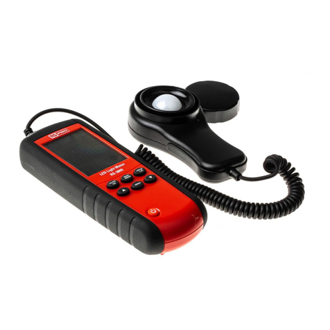
RS PRO ILM 1335 User manual

User Manual
RS PRO ILM 1335
stock number: 123-2221
rspro.com

rspro.com
TABLE OF CONTENTS
TITLE PAGE
1. INTRODUCTION .........................................................1
2. FEATURES..................................................................2
3. SPECIFICATIONS.......................................................3
4. METER DIAGRAM ......................................................5
5. OPERATING INSTRUCTIONS....................................7
6. SETTING THE CALIBRATION FACTOR (CAL).........9
7. SETTING THE SPECTRAL CORRECTION FACTOR
(SCF)..........................................................................10
8. BATTERY CHECK & REPLACEMENT ....................12
9. SPECTRAL SENSITIVITY CHARACTERISTICS.....13
10. MAINTENANCE ......................................................14
11. RECOMMENDED ILLUMINATION..........................15

rspro.com
1
1. INTRODUCTION
•
The ILM 1335 digital light meter is a precision instrument
used to measure illuminance (lux, footcandle).
•
It meets CIE photopic spectral response.
•
It is fully cosine corrected for the angular incidence of light.
•
The meter is a compact, tough and easyto use instrument.
•
The light sensitive component used in the meter is a very
stable, long-life silicon photodiode and spectral response
filter.
•
U.S. Pat. No. Des. 446,135

2
rspro.com
2. FEATURES
•
Light measurement ranging from 0.01 lux ~ 0.1 klux / 0.01
fc ~ 0.01 kfc, respectievely.
•
High accuracy and rapid response.
•
Data-hold function
•
Digital and analogue graphical display
•
Automatic zeroing
•
Meter corrected for spectral relative efficiency.
•
No manual correction factor calculations for non-standard
light sources.
•
Short rise and fall times
•
Peak-hold function
•
Selectable scale – Lux or fc
•
Auto power off after 30 minutes
•
Maximum and minimum measurements
•
Relative reading function
•
User calibration factor (CAL) and spectral correction factor
(SCF) function. (include LED)

rspro.com
3
3. SPECIFICATIONS
•
Display:
3-3/4 digitLCD with high speed42 segmentbargraph.
•
Measuring Range:40.00 lux, 400.0 lux, 4000 lux, 40.00 klux
and 400.0 klux/40.00 fc, 400.0 fc, 4000 fc,
40.00 kfc.
Note : 1fc=10.76 lux , 1klux=1000 lux , 1kfc=1000 fc
•
Overrange Display:LCD will show “OL” symbol.
•
Spectral Response : CIE Photopic. (CIE human eye
response curve).
•
Spectral Accuracy : CIE Vλfunction f ’1≦6%
•
Accuracy:±3% rdg ±0.5% f.s.(±4% rdg ±10 dgts as >
10,000 lux/fc range).
(calibrated to standard incandescent lamp at colour
temperature 2856 K).
•
Repeatability:±2%.
•
Temperature Characteristics:±0.1%/
°C.
•
Sampling Rate : 13.3 times/sec for analogue bar-graph
indication ; 1.3 times/sec for digital
display.
•
Photo Detector:Silicon photo diode and spectral
response filter.

4
rspro.com
•
Operating Temperature & Humidity:
0 to 40°C(32 to 104°F)& 0% to 80% RH.
•
Storage Temperature and Humidity:
-10 to 50°C(14 to 140°F)& 0% to 70% RH.
•
Power Source:6 x 1.5V AAA batteries
•
Battery life ( typical ):400 hours ( zinc-carbon ).
•
Photo detector Lead Length:150 cm ( approx. ).
•
Photo detector Dimensions:92
×
60
×
29 mm
•
Meter Dimensions:150
×
72
×
35 mm
•
Weight:320g.
•
Accessories:Carrycase, instruction manual and battery.

rspro.com
5
4. METER DIAGRAM
lux fc
0
Klux
Kfc
40
20
10
30
1
3
2
5
7
8
4
6
9
1. LCD Display:3-3/4 digit display with a maximum reading of
3999, and the indicating signs of measured
values, unit function symbols, and decimal
points etc are displayed.
2. ON/OFF button.

6
rspro.com
3. Range Selector button: Sequential selection of 40.00 lux,
400.0 lux, 4000 lux, 40.00 klux,
400.0 klux or 40.00 fc, 400.0 fc,
4000 fc, 40.00 kfc. Total of 5 range
for lux and 4 range for fc.
4. Data-Hold button
5. Peak Hold button
6. MX/MN button: Maximum and Minimum reading recall
7. Lux button:Pressing the “Lux” button selects taking
measurement of illuminance in lux.
8. Relative Reading button
9. fc button:Pressing the “fc” button selects measurement of
illuminance in footcandle scale; and, 1 footcandle
=
10.76 lux.
10. Photo Detector.

rspro.com
7
5. OPERATING INSTRUCTIONS
1. Power-up:Press the power button to turn the meter ON or
OFF.
2. Selecting the lux or fc scale:Set the range selection
switch to desired lux or fc range.
3. Remove the photo detector cap and hold the sensor towards
the light source in a horizontal position.
4. Read the illuminance nominal from the LCD display.
5. Overange:If “OL” is shown on the display, the input signal is
too strong and a higher range should be selected.
6. Data-Hold mode:Press the “HOLD” button to select
Data-Hold mode. When HOLD mode is selected, the
illuminance meter stops all further measurements.
Press the “HOLD” button again to exit DATA-HOLD mode
and continue taking readings.
7. Peak-Hold recorder mode:Press “PEAK” button to enter the
P+ recorder mode, and expose the photo detector to light
pulse measuring field. Press “PEAK” button again to exit
PEAK recorder mode, then the meter will resume normal
operation.
8. Maximum and Minimum record mode:Press “MX/MN”
button to cycle through Maximum (MX) reading, Minimum
(MN) reading and current reading (MX/MN blink) recorder
mode. Press “MX/MN” button for two seconds to exit this
mode.

8
rspro.com
9. Relative reading mode:Press “△REL” button to enter
Relative mode. The display will show zero and the current
reading will be stored as the zero reference value. Press
again to exit this mode.
10. When the measurement is completed, replace the photo
detector cap and turn the meter off.

rspro.com
9
6. SETTING the CALIBRATION FACTOR (CAL)
The CAL allows the user to calibrate the meter to any
subject desired. It can be used to calibrate the meter to
another standard subject for which the illuminance is known,
to precisely standardize meters to the same subject.
1. Press power button to turn on the meter.
2. Press “HOLD” button for 2 seconds to enter the setting
mode, the “SEt1” mark is displayed.
3. Press “REL” button to enter CAL setting mode.
4. Press “RANGE” button to position the cursor on the factor
value element to adjust and press “lux” or “fc” button to
change the selected element value from 0.800 to 1.500.
5. Press “REL” button to complete the action and exit.

10
rspro.com
7. SETTING the SPECTRAL CORRECTION FACTOR
(SCF)
When measuring under a light source which has a
considerably different spectral distribution from the meter
calibration light source, the meter will cause an indication
error due to a light deviation of the relative spectral
response from spectral luminous efficiency (Vλ). To correct
this error, the meter has SCF function, allowing you to set
the SCF values. The SCF function can also be used for
correction of indication errors between the meters and for
user calibration under an accurately set light source.
In SCF mode, the following value is displayed.
Display value = Measurement value x SCF
1. Press power button to turn on the meter.
2. Press “HOLD” button for two seconds to enter the setting
mode, the “SEt1” mark is displayed.
3. Press “RANGE” button to select “SEt2”.
4. Press “REL” button to enter the SCF setting mode, the
previously selected light source is displayed.
5. Press “RANGE” button to cycle select the desired light
source.
“L0 uuHitE SCF 0.990”: LED white daylight
“L1 rEd SCF 0.516”: LED red light
“L2 grEEn SCF 1.216”: LED green light
“L3 bLUE SCF 1.475”: LED blue light

rspro.com
11
“L4 YELLO SCF 0.815”: LED yellow light
“L5 PUrPLE SCF 1.148”: LED purple light
“L6 – L9 USEr SCF 1.000”: User-specified
“U0 FLd SCF 0.994”: Daylight fluorescent lamp
“U1 Fuu SCF 0.996”: White fluorescent lamp
“U2 FL3 SCF 1.007”: Three-way fluorescent lamp
“U3 HgL SCF 0.993”: High-pressure mercury vapor lamp
“U4 nAL SCF 0.988”: High-pressure sodium vapor lamp
“U5 Stb SCF 0.996”: Standard light source B
“U6 StC SCF 0.995”: Standard light source C
“U7 uut SCF 0.997”: Equal-energy source (400 – 760nm)
“U8 – U9 USEr SCF 1.000”: User-specified
6. Make a choice
Press “REL” button to confirm the selected light source
and exit this mode.
Press “MX/MN” button to enter select YES “y” or NO “n”
to return the factory all default value mode, the “rE n”
mark is displayed.
Press “RANGE” button to select YES “y” or NO “n”, then
press “REL” button to perform the selected and exit.
Press “PEAK” button to enter the selected light source
SCF value setting mode, press “RANGE” button to
position the cursor on the factor value element to adjust
and press “lux” or “fc” button to change the selected
element value from 0.200 to 5.000.
Press “REL” button to stored the SCF value and exit.

12
rspro.com
7. In the measurement mode, press “lux” button for 2
seconds to enter select enable or disable the SCF function
mode, press “RANGE” button to select “on” or “OFF” then
press “REL” button to stored the selected and exit.
If select “on” will enable SCF function, the bargraph “–”
mark will blinking displayed.
8. In the measuring mode, press “fc” button for 2 seconds to
will show the previously selected light source and the
SCF value for 3 seconds.
8. BATTERY CHECK & REPLACEMENT
Note: The condition of the battery should be checked prior to
use and changed if necessary. The LCD display will
show “BT” symbol when the battery power is not
sufficient for accurate testing.
1. Remove discharged battery and insert new one, respecting
the correct polarity.
2. Dispose of the removed batteries is accordance with local
regulations.
3. If the instrument is likely to remain unused for a long period
it is advised to remove the batteries.

rspro.com
13
9. SPECTRAL SENSITIVITY CHARACTERISTICS
The response of the photo diode with the filters gives a
spectral sensitivity characteristic of the meter which almost
matches the C.I.E. (INTERNATIONAL COMMISSION ON
ILLUMINATION) photopic curve V(λ) as shown in the
following chart.
0
0.2
0.4
0.6
0.8
1
1.2
380
400
420
440
460
480
500
520
540
560
580
600
620
640
660
680
700
720
740
760
780
Wavelength in Nonometers
Relative Sensitivity (%)
0
0.2
0.4
0.6
0.8
1
1.2
Light Meter
CIE

14
rspro.com
10. MAINTENANCE
1. The white plastic disc on the top of the detector should be
cleaned with a damp cloth when necessary.
2. Do not store the instrument where temperature or humidity
is excessively high.
3. The reference level, as marked on the face plate, is the tip
of the photo detector globe.
4. The calibration interval for the photo detector will vary
according to operational conditions, but generally the
sensitivity decreases in direct proportion to the product of
luminous intensity and the operational time. In order to
maintain the basic accuracy of the instrument, periodic
calibration is recommended.

rspro.com
15
11. RECOMMENDED ILLUMINATION
1fc = 10.76 Lux
LOCATIONS
Lux fc
•
OFFICE
Conference, Reception room.
200 ~ 750
18 ~ 70
Clerical work 700 ~ 1,500
65 ~ 140
Typing drafting 1000 ~ 2,000
93 ~ 186
•
FACTORY
Visual work at production line
300 ~ 750
28 ~ 70
Inspection work 750 ~ 1,500
70 ~ 140
Electronic parts assembly line
1500 ~ 3,000
140 ~ 279
Packing work, Entrance
passage 150 ~ 300
14 ~ 28
•
HOTELS
Public room, Cloakroom 100 ~ 200
9 ~ 18
Reception 200 ~ 500
18 ~ 47
Cashier 750 ~ 1000
70 ~ 93
•
STORES
Indoors Stairs Corridor 150 ~ 200
14 ~ 18
Shop window, Packing table
750 ~ 1,500
70~140
Forefront of shop window 1500 ~ 3,000
140 ~279
•
HOSPITALS

16
rspro.com
Sickroom, Warehouse 100 ~ 200
9 ~ 18
Medical Examination room 300 ~ 750
28 ~ 70
Operating room
Emergency Treatmet 750 ~ 1,500
70 ~ 140
•
SCHOOLS
Auditorium, Indoor Gymnasium
100 ~ 300
9 ~ 28
Class room 200 ~ 750
18 ~ 70
Laboratory, Library, Drafting,
room 500 ~ 1,500
47 ~ 140
This manual suits for next models
1
Table of contents
Other RS PRO Measuring Instrument manuals
RS PRO
RS PRO IPM 241 User manual

RS PRO
RS PRO RS-5200 User manual

RS PRO
RS PRO 877-1791 User manual

RS PRO
RS PRO RS-1151 User manual

RS PRO
RS PRO IPM 3600N User manual

RS PRO
RS PRO RSDPB5000 Series User manual

RS PRO
RS PRO ISM 410 User manual

RS PRO
RS PRO RS-171V User manual

RS PRO
RS PRO RS-3809 User manual

RS PRO
RS PRO RS-8809A User manual

RS PRO
RS PRO ICM 20 User manual

RS PRO
RS PRO RS-8880 User manual

RS PRO
RS PRO RS-960 User manual

RS PRO
RS PRO 2377271 User manual

RS PRO
RS PRO RS-9968BT User manual

RS PRO
RS PRO RS-8890 User manual

RS PRO
RS PRO RS-135 User manual

RS PRO
RS PRO RS 1107-UT User manual

RS PRO
RS PRO IM-195 User manual

RS PRO
RS PRO SLM 1353M User manual