InSystems P2L D002 digital User manual


Documentation
Created:
23.05.17
Printed:
23.05.17
File:
BA_P2L-002_V2.1_EN
InSystems Automation GmbH Rudower Chaussee 29 Tel.: +49-30-639 225 10 2-37
12489 Berlin, Germany Fax: +49-30-639 225 16
www.insystems.de Email: info@insystems.de
Der Inhalt dieser Betriebsanleitung obliegt dem Kopierschutz. Er
darf nicht, auch nicht auszugsweise, ohne vorheriges
Einverständnis der InSystems Automation GmbH vervielfältigt
oder an Dritte weiter gegeben werden. Alle technischen
Angaben, Zeichnungen usw. unterliegen dem Gesetz zum Schutz
des Urheberrechts.
EU Declaration of Conformity
InSystems Automation GmbH, Rudower Chaussee 29, 12489 Berlin
for the devices:
Pick-to-Light Sensor P2L-Sensor D002 Digital
Pick-to-Light Sensor P2L-Sensor D002 Digital ESD
Pick-to-Light Sensor P2L-Sensor C002 CAN Bus
Pick-to-Light Sensor P2L-Sensor C002 CAN Bus ESD
We herewith confirm the conformity of the above-mentioned products with European laws and standards:
EU Guideline 2004/108/EG –EMV
EU Guideline 2011/65/EU –RoHS
Following harmonized standards are used:
DIN EN 61326-1:2013-07
Electrical Equipment for Measurement, Control and Laboratory Use
EMV Requirements
The measurements were performed by an EMW laboratory; the measurement report can be viewed on
request.
Authorized representative for technical documentation:
Susanne Dannat, technical documentation
InSystems Automation GmbH
Rudower Chaussee 29
12489 Berlin
Deutschland
Berlin, 01.10.2016
Ort, Datum Dipl. Ing. Henry Stubert, Geschäftsführer

Documentation
Created:
23.05.17
Printed:
23.05.17
File:
BA_P2L-002_V2.1_EN
InSystems Automation GmbH Rudower Chaussee 29 Tel.: +49-30-639 225 10 3-37
12489 Berlin, Germany Fax: +49-30-639 225 16
www.insystems.de Email: info@insystems.de
Der Inhalt dieser Betriebsanleitung obliegt dem Kopierschutz. Er
darf nicht, auch nicht auszugsweise, ohne vorheriges
Einverständnis der InSystems Automation GmbH vervielfältigt
oder an Dritte weiter gegeben werden. Alle technischen
Angaben, Zeichnungen usw. unterliegen dem Gesetz zum Schutz
des Urheberrechts.
1Preliminary Remarks
1.1 General Remarks
–These operating instructions describe the handling of the Pick-to-Light sensors.
–This guide addresses to especially trained staff only.
–Prior to installation and use of the sensors, every user must have read these instructions.
–The sensors should only be installed and adjusted (teach-in procedure) from qualified staff members.
–InSystems Automation GmbH will not be responsible for damages due to improper use and settings of the
sensors.
–The operating instructions must be available during the whole lifetime of the sensors.
If you have any questions, please contact the customer service at InSystems Automation GmbH.
1.2 Safety Remarks
Please observe the instructions for the assembly procedure and the content of the safety remarks in
chapter „Information to this guide“.

Documentation
Created:
23.05.17
Printed:
23.05.17
File:
BA_P2L-002_V2.1_EN
InSystems Automation GmbH Rudower Chaussee 29 Tel.: +49-30-639 225 10 4-37
12489 Berlin, Germany Fax: +49-30-639 225 16
www.insystems.de Email: info@insystems.de
Der Inhalt dieser Betriebsanleitung obliegt dem Kopierschutz. Er
darf nicht, auch nicht auszugsweise, ohne vorheriges
Einverständnis der InSystems Automation GmbH vervielfältigt
oder an Dritte weiter gegeben werden. Alle technischen
Angaben, Zeichnungen usw. unterliegen dem Gesetz zum Schutz
des Urheberrechts.
2Table of Contents
EU Declaration of Conformity 2
1Preliminary Remarks 3
1.1 General Remarks 3
1.2 Safety Remarks 3
2Table of Contents 4
3Product Overview 7
3.1 Acronyms / Definitions 7
4Information to this Guide 8
4.1 Revision Index 8
4.2 Coverage and Target Audience 8
4.2.1 Function of this Document 8
4.2.2 Storage of the Instructions 8
4.2.3 Safety Remarks and General Warnings 8
4.3 Safety remarks 9
4.4 Intended Use 9
4.5 Improper Use 9
4.6 Improper Use 9
4.7 Addition, Changes and Modifications 9
5Product Description P2L Sensor 10
5.1 Available Models 11
5.2 General remarks 11
6Operation Launch 13
6.1 P2L D002 Digital 13
6.2 P2L C002 CAN Bus 13
6.3 Available on Request 13
6.4 Settings 13
6.4.1 LEDs Brightness 13
6.4.2 Pick time 13
7P2L Sensor Assembly and Coverage Area 14
7.1 Required Tools and Assembly Material 14
7.2 P2L Sensor Coverage 14
7.3 Assembly and Sensor Alignment 14
7.4 Sensor Position on the Box 16
7.4.1 Optimized P2L Sensor Position on the Box 16
7.4.2 Not optimized and insufficient Position on the Box 16
7.5 Assembly of ESD Sensors 17
7.6 Assembly Examples 17
8Connection 18
8.1 P2L D002 Digital 18

Documentation
Created:
23.05.17
Printed:
23.05.17
File:
BA_P2L-002_V2.1_EN
InSystems Automation GmbH Rudower Chaussee 29 Tel.: +49-30-639 225 10 5-37
12489 Berlin, Germany Fax: +49-30-639 225 16
www.insystems.de Email: info@insystems.de
Der Inhalt dieser Betriebsanleitung obliegt dem Kopierschutz. Er
darf nicht, auch nicht auszugsweise, ohne vorheriges
Einverständnis der InSystems Automation GmbH vervielfältigt
oder an Dritte weiter gegeben werden. Alle technischen
Angaben, Zeichnungen usw. unterliegen dem Gesetz zum Schutz
des Urheberrechts.
8.1.1 Connector Plug 18
8.1.2 DIP Switch for Brightness and Picking Time 19
8.2 P2L C002 CAN Bus 20
8.2.1 Connector Plug 21
8.2.2 CAN bus Addressing 21
9Use in PLC Systems 22
9.1 Start-up Sequence 22
9.2 Start and Process Error 22
10 Teach-in of P2L Sensors 23
11 P2L Sensor Control 25
11.1 Operation Modes 25
11.2 Consequences by Errors during Picking Operations 26
11.3 Signal Processing P2L D002 Digital 26
11.4 Signal Processing P2L C002 CAN Bus 27
11.4.1 CAN –Data Telegram 27
11.4.2 Message Protocol 27
11.4.3 Communication with the sensor and functions 28
11.4.4 Sensor answers 29
12 LED Error Codes and Troubleshooting 30
13 Special Issues 31
14 P2L mobile supply unit with Pick-to-light sensor 32
14.1 Station Technical Data 32
15 Service 33
15.1 Downloads and FAQ 33
15.2 Customer Service 33
16 Maintenance 33
16.1 Cleaning 33
17 Dispose of Old Devices 33
18 Technical Data P2L sensors 34
18.1 Measurements and Elements of P2L sensors 35
18.1.1 P2L D002 Digital 35
18.1.2 P2L D002 CAN Bus 36

Documentation
Created:
23.05.17
Printed:
23.05.17
File:
BA_P2L-002_V2.1_EN
InSystems Automation GmbH Rudower Chaussee 29 Tel.: +49-30-639 225 10 6-37
12489 Berlin, Germany Fax: +49-30-639 225 16
www.insystems.de Email: info@insystems.de
Der Inhalt dieser Betriebsanleitung obliegt dem Kopierschutz. Er
darf nicht, auch nicht auszugsweise, ohne vorheriges
Einverständnis der InSystems Automation GmbH vervielfältigt
oder an Dritte weiter gegeben werden. Alle technischen
Angaben, Zeichnungen usw. unterliegen dem Gesetz zum Schutz
des Urheberrechts.
2.1 Table of Pictures
Picture 1: Supply shelf 10
Picture 2: Protection class IP53 11
Picture 3: Diagram of sensor area 14
Picture 4: Recommended position 15
Picture 5: Sensor field facing downwards 15
Picture 6: Sensor field facing sideways 15
Picture 7: Optimal P2L position 16
Picture 8: Not optimized P2L position 16
Picture 9: Insufficient P2L positioning 17
Picture 10: Assembly with customer specific bracket 17
Picture 11: Pick-to-light system scheme with P2L digital 18
Picture 12: Socket assignment at P2L digital 18
Picture 13: Schema of DIP switch 19
Picture 14: Bottom of P2L D002 with DIP switch 19
Picture 15: Schema of Pick-to-light system with CAN bus 20
Picture 16: Socket assignment at P2L CAN Bus 21
Picture 17: Schema of DIP switch 21
Picture 18: Bottom of P2L C002 with DIP switch 21
Picture 19: LED signals during startup sequence 22
Picture 20: LED signals by error during startup sequence 22
Picture 21: LED status after successful teach-in after system start 24
Picture 22: LED status after an error during teach-in procedure 24
Picture 23: Example for succeeded picking operation 25
Picture 24: Example for picking error 25
Picture 25: LED signals during correct picking 26
Picture 26: LED signals by wrong picking 26
Picture 27: PLC signals by correct picking operation 26
Picture 28: PLC signals by picking error 27
Picture 29: CAN data telegram 27
Picture 30: LED while setting brightness 29
Picture 31: LED while setting picking time 29
Picture 32: Mobile P2L station with open fronted container (LF 211 ZW PP) by SSI Schäfer 32
Picture 33: Measurements P2L D002 35
Picture 34: Overview P2L digital 35
Picture 35: Measurements P2L CAN bus 36
Picture 36: Overview P2L CAN bus 36
Copyright © 2016, InSystems Automation GmbH

Documentation
Created:
23.05.17
Printed:
23.05.17
File:
BA_P2L-002_V2.1_EN
InSystems Automation GmbH Rudower Chaussee 29 Tel.: +49-30-639 225 10 7-37
12489 Berlin, Germany Fax: +49-30-639 225 16
www.insystems.de Email: info@insystems.de
Der Inhalt dieser Betriebsanleitung obliegt dem Kopierschutz. Er
darf nicht, auch nicht auszugsweise, ohne vorheriges
Einverständnis der InSystems Automation GmbH vervielfältigt
oder an Dritte weiter gegeben werden. Alle technischen
Angaben, Zeichnungen usw. unterliegen dem Gesetz zum Schutz
des Urheberrechts.
3Product Overview
General
P2L sensors are designed for assembly or picking systems. The sensors simplify the
assembly or picking processes for the workers by leading them. The sensor recognizes
if they reach in the right shelf and gives a signal immediately
.
Optic signal:
–
A green LED shows from which shelf the next piece should be taken
.
–A red LED communicates an error.
Models
There are different models for Pick to Light sensor:
–P2L D002 digital
–P2L D002 ESD digital
–P2L C002 CAN Bus
–P2L C002 ESD CAN Bus
Model 002 is a further development of model 001. The sensors of 002 series allow
advanced settings and an automatized teaching-in process (adaption to the geometry
of the container and fill height).
You can read more details about the sensors in the relevant chapter.
Service
InSystems Automation GmbH allows a free sensor test:
We provide test sensors for a functional test to your conditions. Please contact our
customer service (See chapter 15.2)
3.1 Acronyms / Definitions
CAN
Controller Area Network (serial Fieldbus system)
DIP
Dual in-line package
ESD
Electro static safe device
SLC
Small Load Carrier
MFC
Material Flow Control
P2L
Pick-to-light
PLC
Programmable Logic Controller

Documentation
Created:
23.05.17
Printed:
23.05.17
File:
BA_P2L-002_V2.1_EN
InSystems Automation GmbH Rudower Chaussee 29 Tel.: +49-30-639 225 10 8-37
12489 Berlin, Germany Fax: +49-30-639 225 16
www.insystems.de Email: info@insystems.de
Der Inhalt dieser Betriebsanleitung obliegt dem Kopierschutz. Er
darf nicht, auch nicht auszugsweise, ohne vorheriges
Einverständnis der InSystems Automation GmbH vervielfältigt
oder an Dritte weiter gegeben werden. Alle technischen
Angaben, Zeichnungen usw. unterliegen dem Gesetz zum Schutz
des Urheberrechts.
4Information to this Guide
4.1 Revision Index
Version
Date
Changes
Name
1.0
13.07.2015
First version
4.2 Coverage and Target Audience
The following guide is valid for the described P2L sensor. It describes safety-compliant and efficient handling of
sensors and explains the necessary procedures during installations and operations. Operating instructions
must be read and understood from everyone executing following tasks:
–Installation
–Setting
–Closing down and removal
4.2.1 Function of this Document
These operating instructions contains all necessary information for proper assembling, electric installation,
putting into operation and operation modus of P2L sensors.
These operating instructions do not refer to the functions of assembly or picking system, which is integrated in
P2L sensors. This information can be found in the operating instructions of the system manufacturer.
4.2.2 Storage of the Instructions
The operating instructions must be always available in the place of use of the described sensors.
4.2.3 Safety Remarks and General Warnings
In these operating instructions, safety remarks and general warnings with following symbols and contents are
used:
Special warning
signs
Safety warnings are provided with an additional symbol when referring to specific
hazards.
Text Layout Remarks
Instructions
Description
Operating instructions are numbered consecutively in the margin column (1,2 etc.)
are structured as follows:
Description of an operating instruction:
This symbol identifies an operating step. An operating instruction contains one
or more consecutive operating steps.
This symbol underlines useful tips and extra information.
This symbol identifies the end of an operating instruction.

Documentation
Created:
23.05.17
Printed:
23.05.17
File:
BA_P2L-002_V2.1_EN
InSystems Automation GmbH Rudower Chaussee 29 Tel.: +49-30-639 225 10 9-37
12489 Berlin, Germany Fax: +49-30-639 225 16
www.insystems.de Email: info@insystems.de
Der Inhalt dieser Betriebsanleitung obliegt dem Kopierschutz. Er
darf nicht, auch nicht auszugsweise, ohne vorheriges
Einverständnis der InSystems Automation GmbH vervielfältigt
oder an Dritte weiter gegeben werden. Alle technischen
Angaben, Zeichnungen usw. unterliegen dem Gesetz zum Schutz
des Urheberrechts.
Lists
Lists are bulleted.
References to
images
Reference to numbered images are put into brackets:
If the same picture or table is quoted more than once in a paragraph, only the first
cross-reference contains the indication of the picture [Picture 10 / 1]. The following
cross-references contain only the position number [2].
4.3 Safety remarks
Follow all safety remarks and warnings in this user manual.
4.4 Intended Use
The P2L sensors are designed with the purpose of supervising manually picking in a box. They should only be
used for this purpose. Other uses than the ones described in this guide are not allowed. For damages after
improper use, InSystems Automation GmbH declines any liability.
4.5 Improper Use
Another use as described in chapter Intended Use is considered improper. During improper use, unpredictable
risks might occur. For damages after improper use, InSystems Automation GmbH declines any liability.
Examples for improper use are:
–Untypical use
–Passing fixed technical limits
–Modification, which are not approved by the manufacturer
–Operations in explosive atmosphere
–Contamination with aggressive chemicals, acids or their vapors.
4.6 Improper Use
Even preventive measurements do not avoid improper use. The following paragraphs describe proper use. All
other uses are defined as improper use.
4.7 Addition, Changes and Modifications
Addition, changes and modifications on the sensors can cause hazards.
–Additions, changes and modifications should be only made after consultation with the manufacturer and
his written approval.
[Picture 10 / 1]
Position number
Image number
Documentation
Created:
23.05.17
Printed:
23.05.17
File:
BA_P2L-002_V2.1_EN
InSystems Automation GmbH Rudower Chaussee 29 Tel.: +49-30-639 225 10 10-37
12489 Berlin, Germany Fax: +49-30-639 225 16
www.insystems.de Email: info@insystems.de
Der Inhalt dieser Betriebsanleitung obliegt dem Kopierschutz. Er
darf nicht, auch nicht auszugsweise, ohne vorheriges
Einverständnis der InSystems Automation GmbH vervielfältigt
oder an Dritte weiter gegeben werden. Alle technischen
Angaben, Zeichnungen usw. unterliegen dem Gesetz zum Schutz
des Urheberrechts.
–Unauthorized changes on the sensors or their components invalidate the guarantee and liability by the
manufacturer.
–The CE Definition of Conformity is only valid, if the sensor can be clearly identified. This can only happen if
the manufacturer label is intact. A change or distortion of the manufacturer specification is not allowed
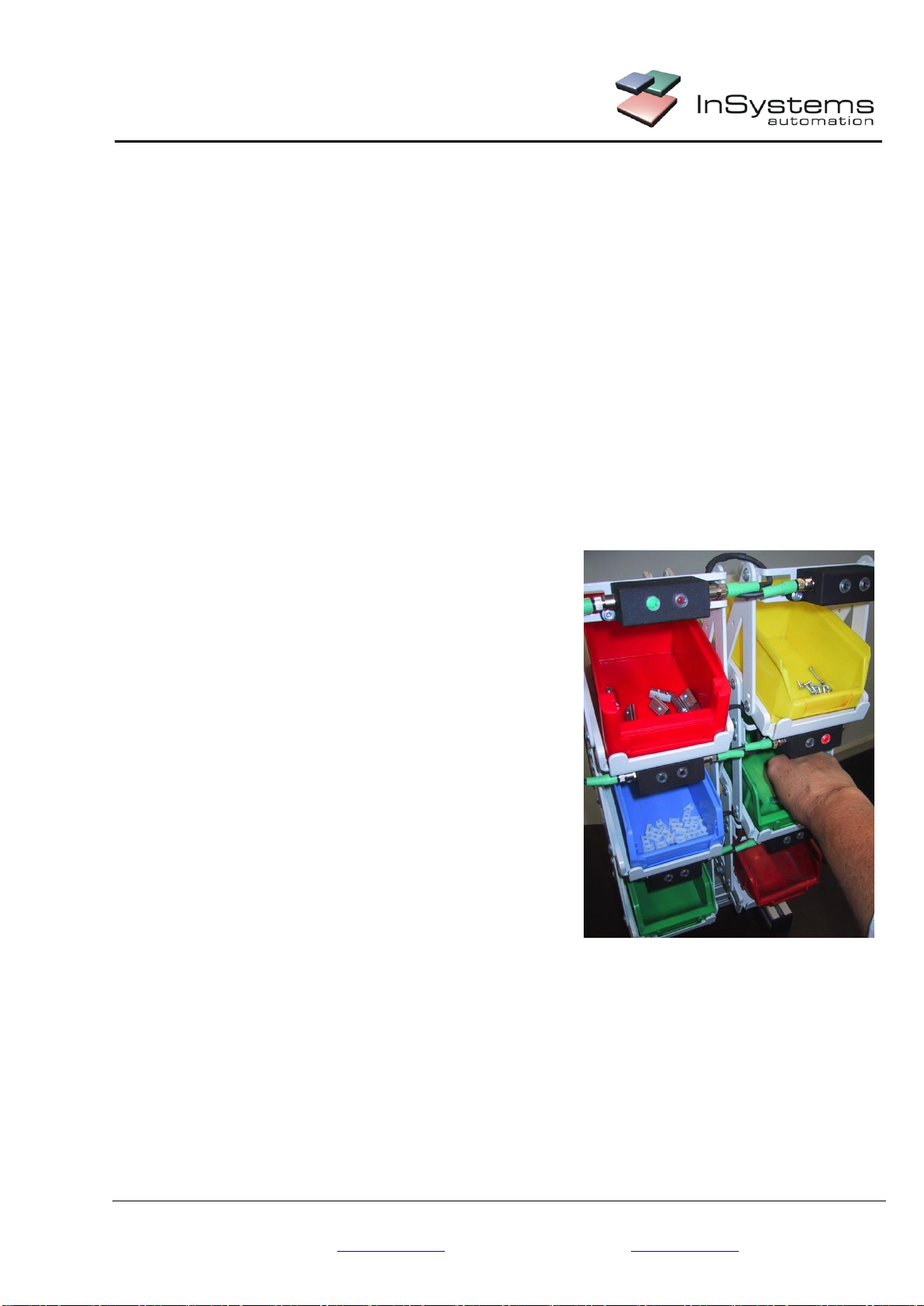
5Product Description P2L Sensor
P2L sensors are designed for assembly and picking systems. The sensors simplify the assembly and picking
procedures for the operators, since the light signals lead each operator. The sensor recognizes if the right or the
wrong shelf is reached and signalizes it immediately
.
Optical signaling:
–
A green LED shows from which shelf the ware should be picked
–A red LED means an error.
The consequences of an error are defined by the customer in the PLC.
Example
Figure 1 shows an error, which is
immediately reported by the red LED. The
green LED lights up on the container, from
where the piece should have been taken
out.
Picture 1: Supply shelf
Documentation
Created:
23.05.17
Printed:
23.05.17
File:
BA_P2L-002_V2.1_EN
InSystems Automation GmbH Rudower Chaussee 29 Tel.: +49-30-639 225 10 11-37
12489 Berlin, Germany Fax: +49-30-639 225 16
www.insystems.de Email: info@insystems.de
Der Inhalt dieser Betriebsanleitung obliegt dem Kopierschutz. Er
darf nicht, auch nicht auszugsweise, ohne vorheriges
Einverständnis der InSystems Automation GmbH vervielfältigt
oder an Dritte weiter gegeben werden. Alle technischen
Angaben, Zeichnungen usw. unterliegen dem Gesetz zum Schutz
des Urheberrechts.
Process Safety
With P2L sensors, a high process safety in assembly and picking operations can be reached. These represent a
great economic advantage, if a lot of variants and of small batches are available.
The sensor is teachable and can be fit to different container forms and filling heights. The P2L sensor is
optimized for the current set of containers, materials and filling heights.
The teaching signal can be sent by a button or integrated in the PLC start routine.
The small construction and the small minimal distance (see chapter 7.2) allow very flat racking levels, which
ensure ergonomic deployment architecture with shorts handling ranges.
A removal from a compartment does not have to be confirmed, because the P2L sensor recognizes it
automatically.
For big assembly systems with lots of sensors, the use of P2L sensors with CAN bus is recommended,
because the wiring is less time-consuming: all P2L C002 are wired in series and only a supply line to PLC
is required.
With P2L C002 sensor the LEDs over the CAN Bus can be individually controlled, depending on the
process requirements.
5.1 Available Models
Type
Digital
Can Bus
Standard
P2L D002
P2L C002
ESD
P2L D002 ESD
P2L C002 ESD
Technical Data see chapter 0
5.2 General remarks
Der P2L-Sensor is designed to fulfill the requirements of the protection class IP53.
Picture 2: Protection class IP53

Documentation
Created:
23.05.17
Printed:
23.05.17
File:
BA_P2L-002_V2.1_EN
InSystems Automation GmbH Rudower Chaussee 29 Tel.: +49-30-639 225 10 12-37
12489 Berlin, Germany Fax: +49-30-639 225 16
www.insystems.de Email: info@insystems.de
Der Inhalt dieser Betriebsanleitung obliegt dem Kopierschutz. Er
darf nicht, auch nicht auszugsweise, ohne vorheriges
Einverständnis der InSystems Automation GmbH vervielfältigt
oder an Dritte weiter gegeben werden. Alle technischen
Angaben, Zeichnungen usw. unterliegen dem Gesetz zum Schutz
des Urheberrechts.
–Keep the sensor away from moisture, since it might lead to corrosion of the electric components in the
casing
–Keep the recommended operating temperature (-10 until +50 °C) and don’t expose the sensor to extreme
temperature differences, since this might lead to dysfunction and shorten the lifetime of the sensor.
–
Avoid violent impacts and electric discharges that can damage the P
2L sensor.
–
Do not open the casing of a P2L sensor. The device contains high-precision electronic components, which
might be damaged
.
For damages resulting from non-compliance with the present instructions, we do not grant any warranty.

Documentation
Created:
23.05.17
Printed:
23.05.17
File:
BA_P2L-002_V2.1_EN
InSystems Automation GmbH Rudower Chaussee 29 Tel.: +49-30-639 225 10 13-37
12489 Berlin, Germany Fax: +49-30-639 225 16
www.insystems.de Email: info@insystems.de
Der Inhalt dieser Betriebsanleitung obliegt dem Kopierschutz. Er
darf nicht, auch nicht auszugsweise, ohne vorheriges
Einverständnis der InSystems Automation GmbH vervielfältigt
oder an Dritte weiter gegeben werden. Alle technischen
Angaben, Zeichnungen usw. unterliegen dem Gesetz zum Schutz
des Urheberrechts.
6Operation Launch
6.1 P2L D002 Digital
With following steps the P2L D002 will be installed and launched:
Assembly the sensor in the racking levels where the material is stored see chapter 7.
Connect the sensors to the PLC see chapter 8.1.
Turn on the PLC.
The teach-in procedure of container geometry and filling heights runs automatically see chapter 0
6.2 P2L C002 CAN Bus
With following steps the P2L D002 will be installed and launched:
Assembly the sensor in the racking levels where the material is stored see chapter 7.
Set a serial connection between sensors and a connection to PLC see chapter 0
Set the sensor addresses at the DIP switches see chapter 9.
Turn on the PLC
The teach-in procedure of container geometry and filling heights runs automatically see chapter 0
6.3 Available on Request
The process workflow (pick-sequence and reaction by errors) is defined in the PLC. A material and assembly
workflow manager, the visualization of assembly steps, as well as the saving of process parameters can be
performed by extra PC software.
6.4 Settings
Settings at D002 are performed using a DIP switch see chapter 8.1.2 und at C002 using a CAN bus see 11.4.3
6.4.1 LEDs Brightness
Depending on the working environment and installation (at eye level), the brightness can dazzle and you might
want to dim the lights. You can choose between four brightness levels.
6.4.2 Pick time
Having small pieces or pieces, which get easily caught (for example coil springs), the pick procedure might take
longer. In this case, the picking time should be extended in the sensor, so that no error message is triggered.

Documentation
Created:
23.05.17
Printed:
23.05.17
File:
BA_P2L-002_V2.1_EN
InSystems Automation GmbH Rudower Chaussee 29 Tel.: +49-30-639 225 10 14-37
12489 Berlin, Germany Fax: +49-30-639 225 16
www.insystems.de Email: info@insystems.de
Der Inhalt dieser Betriebsanleitung obliegt dem Kopierschutz. Er
darf nicht, auch nicht auszugsweise, ohne vorheriges
Einverständnis der InSystems Automation GmbH vervielfältigt
oder an Dritte weiter gegeben werden. Alle technischen
Angaben, Zeichnungen usw. unterliegen dem Gesetz zum Schutz
des Urheberrechts.
7P2L Sensor Assembly and Coverage Area
P2L sensor is easy to install and can be quickly integrated in existing assembly workplaces.
Customer tailored integration are available on request.
Assembly is done by screwing two screws or brackets on a fitting retaining plate (not included in scope of
delivery). The gripping range must be within the maximum range of 150 mm, optimally at 100 mm.
For a better integration of P2L-sensors in your deployment architecture, CAD data with measurements are
available on our download page, in order for you to find their optimal position.
7.1 Required Tools and Assembly Material
In order to fix a P2L sensor, two M4 screws with a minimal length of 10 Millimeter are needed. For the ESD
variants, two additional external teeth lock washers (DIN 6797) are required.
7.2 P2L Sensor Coverage
Sensor coverage reaches between 20
and
150 mm. Optimal results are reached at a distance of
100 mm.
Picture 3: Diagram of sensor area
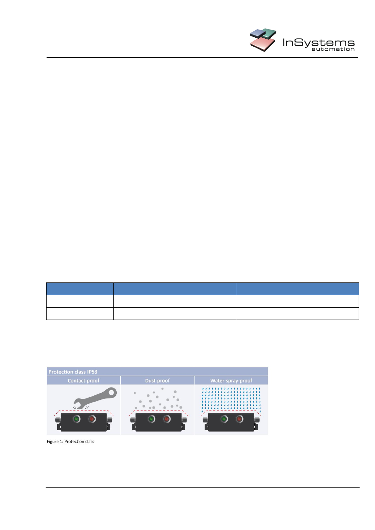
7.3 Assembly and Sensor Alignment
A downward-facing alignment is recommended. The sensor can also be aligned upward or side-facing, but it
might be become susceptible to failures because of dirt (case-by-case assessment).
Documentation
Created:
23.05.17
Printed:
23.05.17
File:
BA_P2L-002_V2.1_EN
InSystems Automation GmbH Rudower Chaussee 29 Tel.: +49-30-639 225 10 15-37
12489 Berlin, Germany Fax: +49-30-639 225 16
www.insystems.de Email: info@insystems.de
Der Inhalt dieser Betriebsanleitung obliegt dem Kopierschutz. Er
darf nicht, auch nicht auszugsweise, ohne vorheriges
Einverständnis der InSystems Automation GmbH vervielfältigt
oder an Dritte weiter gegeben werden. Alle technischen
Angaben, Zeichnungen usw. unterliegen dem Gesetz zum Schutz
des Urheberrechts.
Recommended
Installation Position
Standard installation position
Sensor field facing downwards
Less susceptible for
contamination
No influence by ambient light
Picture 4: Recommended position
Possible Installation
Position (case-by-
case assessment)
Standard installation position –Sensor
field facing upwards
Possible, but more susceptible for
contamination:
by dirt deposit on the sensor
by ambient light
Picture 5: Sensor field facing downwards
Possible Installation
Position (case-by-
case assessment)
Standard installation –Sensor field facing
sideways
Possible, but more susceptible for
contamination:
by dirt deposit on the sensor
by ambient light
Picture 6: Sensor field facing sideways
Documentation
Created:
23.05.17
Printed:
23.05.17
File:
BA_P2L-002_V2.1_EN
InSystems Automation GmbH Rudower Chaussee 29 Tel.: +49-30-639 225 10 16-37
12489 Berlin, Germany Fax: +49-30-639 225 16
www.insystems.de Email: info@insystems.de
Der Inhalt dieser Betriebsanleitung obliegt dem Kopierschutz. Er
darf nicht, auch nicht auszugsweise, ohne vorheriges
Einverständnis der InSystems Automation GmbH vervielfältigt
oder an Dritte weiter gegeben werden. Alle technischen
Angaben, Zeichnungen usw. unterliegen dem Gesetz zum Schutz
des Urheberrechts.
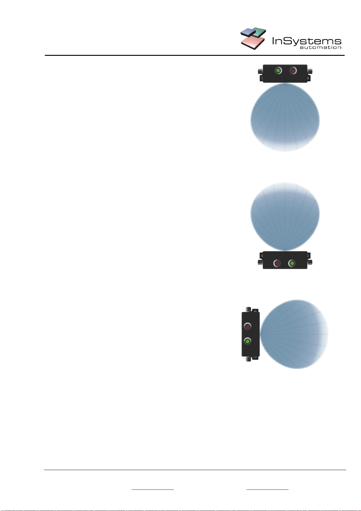
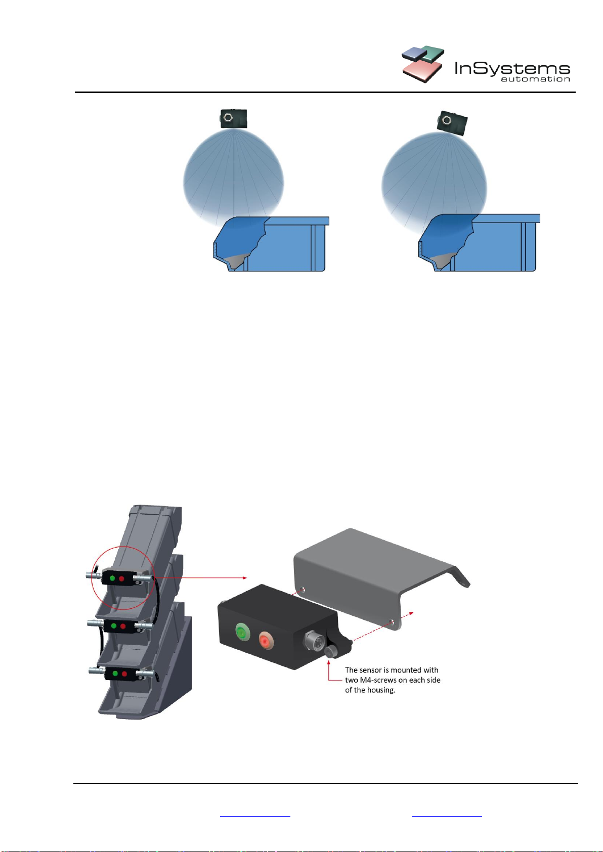
7.4 Sensor Position on the Box
7.4.1 Optimized P2L Sensor Position on the Box
Example for
an optimal position
of P2L sensor
Picture 7: Optimal P2L position
The range of the P2L sensor covers the whole box.
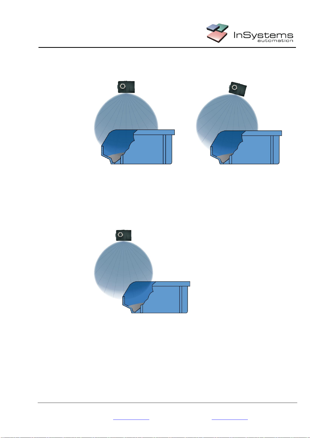
7.4.2 Not optimized and insufficient Position on the Box
Example for
a non-optimized
position of P2L
sensor
Picture 8: Not optimized P2L position
The sensor just covers a corner of the box. Errors during teach-in and picking procedures may occur.
The sensor range is too far from the box and can supervise only a part of it. The procedure might not be
recognized or the next box might be supervised instead.
Documentation
Created:
23.05.17
Printed:
23.05.17
File:
BA_P2L-002_V2.1_EN
InSystems Automation GmbH Rudower Chaussee 29 Tel.: +49-30-639 225 10 17-37
12489 Berlin, Germany Fax: +49-30-639 225 16
www.insystems.de Email: info@insystems.de
Der Inhalt dieser Betriebsanleitung obliegt dem Kopierschutz. Er
darf nicht, auch nicht auszugsweise, ohne vorheriges
Einverständnis der InSystems Automation GmbH vervielfältigt
oder an Dritte weiter gegeben werden. Alle technischen
Angaben, Zeichnungen usw. unterliegen dem Gesetz zum Schutz
des Urheberrechts.
Example for
a non-optimized
position of P2L
sensor
Picture 9: Insufficient P2L positioning
The sensor just covers a corner of the box. Errors during teach-in and picking procedures may occur.
7.5 Assembly of ESD Sensors
The P2L ESD sensor is already grounded through the connecting plug. However, we recommend to ground the
housing during the assembly procedure with external teeth lock washers, in order to provide maximal safety.
7.6 Assembly Examples
Demo of a C002 P2L sensor, which is mounted over Bosch grip plates with an angled bracket. The sensor is
fastened to the bracket with two M4 screws.
Picture 10: Assembly with customer specific bracket

Documentation
Created:
23.05.17
Printed:
23.05.17
File:
BA_P2L-002_V2.1_EN
InSystems Automation GmbH Rudower Chaussee 29 Tel.: +49-30-639 225 10 18-37
12489 Berlin, Germany Fax: +49-30-639 225 16
www.insystems.de Email: info@insystems.de
Der Inhalt dieser Betriebsanleitung obliegt dem Kopierschutz. Er
darf nicht, auch nicht auszugsweise, ohne vorheriges
Einverständnis der InSystems Automation GmbH vervielfältigt
oder an Dritte weiter gegeben werden. Alle technischen
Angaben, Zeichnungen usw. unterliegen dem Gesetz zum Schutz
des Urheberrechts.
8Connection
8.1 P2L D002 Digital
Each digital P2L sensor is connected by a separate cable with the PLC.
P2L sensors are supplied with power by the PLC.
Picture 11: Pick-to-light system scheme with P2L digital
1. Digital P2L-Sensors
2. PLC with E/A (I/O)
3. MFR for
- Control of assembly sequence
- Control of the containers
- Visualizing etc.
8.1.1 Connector Plug
Picture 12: Socket assignment at P2L digital
Documentation
Created:
23.05.17
Printed:
23.05.17
File:
BA_P2L-002_V2.1_EN
InSystems Automation GmbH Rudower Chaussee 29 Tel.: +49-30-639 225 10 19-37
12489 Berlin, Germany Fax: +49-30-639 225 16
www.insystems.de Email: info@insystems.de
Der Inhalt dieser Betriebsanleitung obliegt dem Kopierschutz. Er
darf nicht, auch nicht auszugsweise, ohne vorheriges
Einverständnis der InSystems Automation GmbH vervielfältigt
oder an Dritte weiter gegeben werden. Alle technischen
Angaben, Zeichnungen usw. unterliegen dem Gesetz zum Schutz
des Urheberrechts.
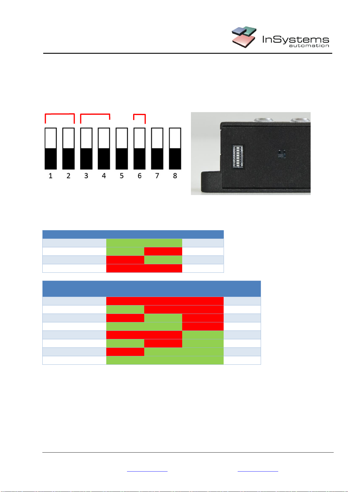
8.1.2 DIP Switch for Brightness and Picking Time
LED brightness and picking time can be set with the DIP switch on the bottom.
Four brightness levels and picking times from 500 to 8000 ms can be configured.
Picture 13: Schema of DIP switch
Picture 14: Bottom of P2L D002 with DIP switch
DIP Switch
1
2
Brightness
Status
ON
ON
25%
Status
ON
OFF
50%
Status
OFF
ON
75%
Status
OFF
OFF
100%
DIP Switch
3
4
6
Picking
Time
Status
OFF
OFF
OFF
500 ms
Status
ON
OFF
OFF
1500 ms
Status
OFF
ON
OFF
2500 ms
Status
ON
ON
OFF
3500 ms
Status
OFF
OFF
ON
4500 ms
Status
ON
OFF
ON
5500 ms
Status
OFF
ON
ON
6500 ms
Status
ON
ON
ON
8000 ms
The other DIP switches are not used.
Upon delivery of the P2L sensors all DIP switches are set to OFF.
Documentation
Created:
23.05.17
Printed:
23.05.17
File:
BA_P2L-002_V2.1_EN
InSystems Automation GmbH Rudower Chaussee 29 Tel.: +49-30-639 225 10 20-37
12489 Berlin, Germany Fax: +49-30-639 225 16
www.insystems.de Email: info@insystems.de
Der Inhalt dieser Betriebsanleitung obliegt dem Kopierschutz. Er
darf nicht, auch nicht auszugsweise, ohne vorheriges
Einverständnis der InSystems Automation GmbH vervielfältigt
oder an Dritte weiter gegeben werden. Alle technischen
Angaben, Zeichnungen usw. unterliegen dem Gesetz zum Schutz
des Urheberrechts.
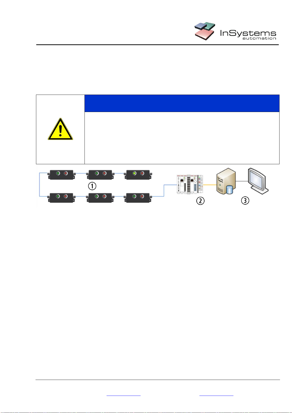
8.2 P2L C002 CAN Bus
The P2L sensors with CAN bus are connected in a row by a cable with 4 pins M8 connector (not included in
scope of delivery) to the CAN bus module of PLC.
Up to 126 sensors can be connected in a system (limited by the possible addresses). See chapter 8.2.2
The P2L sensor are supplied with power by the CAN Bus line.
CAUTION
For a large number of P2L sensors with CAN bus in a system, a separate power
supply should be provided.
Otherwise, the voltage demand at start can’t be covered and it might come to errors.
Provide the necessary power supply, so that the CAN bus system can work
properly.
Picture 15: Schema of Pick-to-light system with CAN bus
1. P2L sensors with CAN bus in a row
2. PLC with CAN Bus
3. MFR for
- Control of assembly sequence
- Control of the containers,
- Visualizing etc.
This manual suits for next models
3
Table of contents
Other InSystems Accessories manuals


