Intec PolyGard 2 SC2 User manual
INTEC Controls | 12700 Stowe Drive, Suite 100, Poway, CA 92064 | Ph: (858) 578.7887 & (888) GO.INTEC | inteccontrols.com
April 13, 2020 – Revision
Toxic (E-), Combustible (P-) and Infrared (I-CO2) Gases
PolyGard®2 SC2 & AT6 Sensors
User Manual
November 2019

INTEC Controls | 12700 Stowe Drive, Suite 100, Poway, CA 92064 | Ph: (858) 578.7887 & (888) GO.INTEC | inteccontrols.com
Specifications subject to change without notice. | Tox_D_1119, Ex_D_1119, CO2_D_0320 | USA 200413 | Page 2of 17
SC2-AT6 – UserManual
1 Functional Description....................................................................................................................................3
1.1 General......................................................................................................................................................3
1.2 Measuring Mode........................................................................................................................................3
1.3 Special Mode.............................................................................................................................................3
1.4 Sensor Element for Toxic Gases and Oxygen........................................................................................... 3
1.5 Sensor Element for Combustible Gases .................................................................................................. 4
1.6 Infrared Sensor Element for CO2...............................................................................................................4
2 Installation........................................................................................................................................................5
2.1 Mounting Instructions ................................................................................................................................5
3 Electrical Connection ......................................................................................................................................6
3.1 Plug Connection (SC2)..............................................................................................................................6
3.2 Terminal Connection (AT6) ........................................................................................................................6
4 Commissioning................................................................................................................................................6
4.1 Installation of Sensor Cartridge .................................................................................................................7
4.2 Registration of the Sensor Cartridge .........................................................................................................7
5 Calibration ........................................................................................................................................................7
5.1 Calibration Process ...................................................................................................................................8
5.2 Exchange of Sensor Cartridge ..................................................................................................................9
6 Inspection and Service....................................................................................................................................9
6.1 Inspection ..................................................................................................................................................9
6.2 Service and Calibration ...........................................................................................................................10
7 Troubleshooting............................................................................................................................................. 11
7.1 Indicators at the SC2............................................................................................................................... 11
7.2 Indicators at the AT6................................................................................................................................ 11
7.3 Printed Circuit Board ............................................................................................................................... 11
7.4 Sensor Cartridge (Messages at the Tool / Controller) ............................................................................. 11
8 Cross-sensitivity Data ...................................................................................................................................12
9 Technical Data................................................................................................................................................12
9.1 SC2 (Sensor Cartridge)...........................................................................................................................12
9.2 AT6 ..........................................................................................................................................................12
9.3 Sensor Element....................................................................................................................................... 13
9.4 Cross Sensitivity - Sensor Cartridge (SC2 / AT6) / Sensor Element ....................................................... 15
10 Figures.......................................................................................................................................................... 16
11 Part Disposal ................................................................................................................................................17
12 Notes and General Information ..................................................................................................................17
13 Intended Product Application.....................................................................................................................17
13.1 Installers’ Responsibilities ..................................................................................................................... 17
13.2 Maintenance.......................................................................................................................................... 17
13.3 Limited Warranty ...................................................................................................................................17

INTEC Controls | 12700 Stowe Drive, Suite 100, Poway, CA 92064 | Ph: (858) 578.7887 & (888) GO.INTEC | inteccontrols.com
Specifications subject to change without notice. | Tox_D_1119, Ex_D_1119, CO2_D_0320 | USA 200413 | Page 3of 17
SC2-AT6 – UserManual
Intended Use
The SC2 sensors are designed for the measurement of toxic gases and oxygen in a wide range of applications with
the PolyGard®2 Series. The AT6 sensor/transmitter operates with 24 VDC and outputs an analog 4-20 mA standard
signal. Both the SC2 sensor cartridge and AT6 sensor/transmitter utilizes similar technologies and thus collective
referred to as same (“sensor cartridge”,”sensors”) in this document unless otherwise noted.
The sensors must not be used in potentially explosive atmospheres. They must only be employed in areas within the
environmental conditions as specied in the Technical Data.
1 Functional Description
1.1 General
The SC2 sensor includes a microprocessor for measurement value processing in addition to the gas sensor element
and the measuring amplier. All data and measured values of the sensor element are stored in a fail- safe way in the
microprocessor and are digitally transferred via the local bus to the PG2 devices. The calibration management is also
integrated in the microprocessor of the sensor cartridge.
The AT6 sensor/transmitter works according to the same principle as the SC2 series with the exception that the AT6
outputs an analog signal of 4-20 mA (2-10 V as an option).
1.2 Measuring Mode
See description on datasheet for the specic PG2 device.
1.3 Special Mode
See description on datasheet for the specic PG2 device.
1.4 Sensor Element for Toxic Gases and Oxygen
The sensor element is a sealed electro-chemical cell with three electrodes, sensing, reference and counter or with two
electrodes, sensing and reference. The ambient air to be monitored diuses through a membrane lter into the liquid
electrolyte of the sensor. The chemical process of the measurement is one of oxidation where one molecule of the
target gas is exchanged for one molecule of oxygen. The reaction drives the oxygen molecule to the counter electrode,
generating a DC microampere signal between the sensing and reference electrodes. This signal is linear to the volume
concentration of the sensed gas. The signal is evaluated by the connected amplier and transformed into a linear
output signal.
Electrochemical processes always lead by-and-by to a loss of sensitivity. Therefore regular calibration of zero- point
and gain is necessary. See section 5.
There is a small quantity of corrosive liquid in the sensor element. If in case of damage persons or
objects touch the liquid, clean the aected areas immediately and carefully as possible with tap water.
Out of use sensors must be disposed in the same way as batteries.
Certain substances and gases in the ambient air to be monitored can aect the sensitivity of the sensor element or
destroy the sensor completely. This is considered sensor poisoning.
The following are currently known:
• Polymerizing substances, such as ethylene oxide, acrylonitrile, butadiene, styrene, silicone.
• Corrosive substances, such as halogenated hydrocarbons.
• Catalytic poisons, such as sulfur and phosphor compounds, silicon compounds, metal vapors.

INTEC Controls | 12700 Stowe Drive, Suite 100, Poway, CA 92064 | Ph: (858) 578.7887 & (888) GO.INTEC | inteccontrols.com
Specifications subject to change without notice. | Tox_D_1119, Ex_D_1119, CO2_D_0320 | USA 200413 | Page 4of 17
SC2-AT6 – UserManual
1.5 Sensor Element for Combustible Gases
The integrated sensor works according to the catalytic bead principle. The ambient air to be monitored diuses through
a sintered metal disk into the sensor. Here the combustible gases and vapours are burned catalytically at a heated
detector element (pellistor). The resulting combustion heat also heats up the detector element. This heating changes
the resistance of the detector element which is proportional to the partial pressure of the combustible gases.
In addition to the catalytic detector element, the sensor also has a similarly heated inactive compensator element.
Both elements are part of a Wheatstone measuring bridge. Environmental inuences such as temperature, air humidity
or thermal conductivity of the ambient air to be monitored aect both elements to the same extent so that these
inuences have no signicant eect on the measuring signal.
Certain substances and gases in the ambient air to be monitored can aect the sensitivity of the sensor
element or destroy the sensor completely. This is called poisoning.
The following are currently known:
• Polymerising substances, such as ethylene oxide, acrylonitrile, butadiene, styrene, silicone.
• Corrosive substances, such as halogenated hydrocarbons.
• Catalytic poisons, such as sulphur and phosphor compounds, silicon compounds, metal vapours.
• Organic solvents
For testing the sensor, do not use a lighter. If gassed with a lighter the sensor cannot be employed for reliable
measurement and must rst be recalibrated. The sensor may be damaged, and the calibration should then be
repeated at much shorter intervals. In addition, the resulting amount of heat can lead to the mechanical destruction of
the sensor. The product warranty is void by fumigation with a lighter.
1.6 Infrared Sensor Element for CO2
The integrated sensor is based on the principle of the infrared absorption of gases and accomplishes highest
requirements concerning accuracy, reliability and economy. The sensor technology uses the individual absorption
spectrum of the carbon dioxide gas and determines its exact concentration through its accurate, quantitative analysis.
The infrared principle nearly eliminates the cross-sensitivity to other gases.
An integrated evaluation electronic system reliably compensates all drift and temperature inuences and therefore a
genuine measurement result is guaranteed.
Certain substances and gases in the monitored ambient can aect the sensitivity of the sensor element
or destroy the sensor completely. This is called poisoning.
The following are currently known:
• Polymerising substances, such as ethylene oxide, acrylonitrile, butadiene, styrene, silicone
• Corrosive substances, such as halogenated hydrocarbons
• Catalytic poisons, such as sulphur and phosphor compounds, silicon compounds, metal vapours
INTEC Controls | 12700 Stowe Drive, Suite 100, Poway, CA 92064 | Ph: (858) 578.7887 & (888) GO.INTEC | inteccontrols.com
Specifications subject to change without notice. | Tox_D_1119, Ex_D_1119, CO2_D_0320 | USA 200413 | Page 5of 17
SC2-AT6 – UserManual
2 Installation
Electronics can be destroyed by electrostatic discharge (ESD). Therefore installation work should
be done only by persons connected to ground, e. g. by standing on a conductive oor or by taking
appropriate grounding measures (acc. to DIN EN 100015).
2.1 Mounting Instructions
• Choose mounting location of the sensor
according to the local regulations.
• Consider ventilation conditions! Do not
mount the sensor near the airow (air
passages, suction holes etc.).
• Mount the sensor at a location with
minimum vibration and minimum variation
in temperature (avoid direct sunlight).
• Avoid locations where water, oil etc. may
inuence proper operation and where
mechanical damage might be possible.
• Provide adequate space around the
sensor for maintenance and calibration
work.
INTEC Controls | 12700 Stowe Drive, Suite 100, Poway, CA 92064 | Ph: (858) 578.7887 & (888) GO.INTEC | inteccontrols.com
Specifications subject to change without notice. | USA 200303 | Page 5of 5
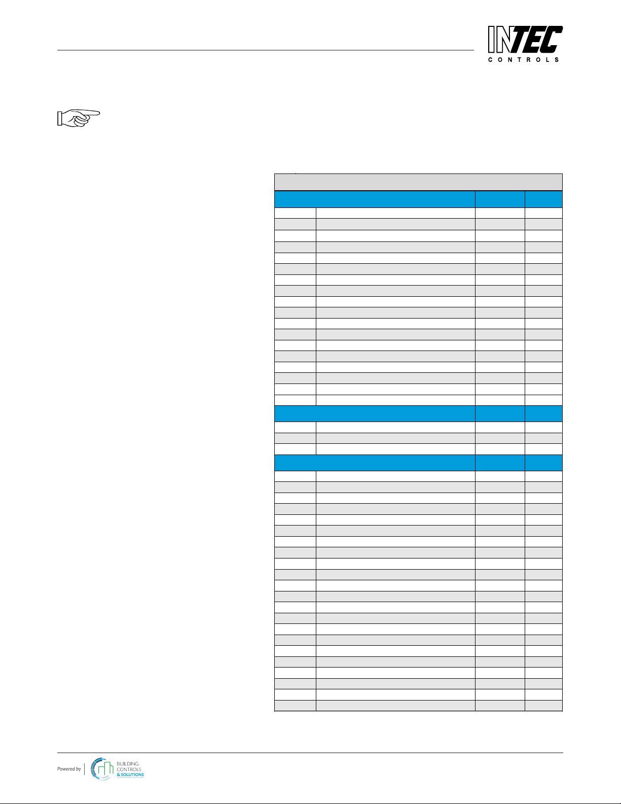
ORDERING INFORMATION
SC2 - XXXXX-X
SC2
Example, ordering part number:
SC2-E1110-E
Conguration includes:
X-Change Replacement Sensor:
• Carbon Monoxide, 0-250 ppm
Gas Sensor & Range
# TOXIC GASES AND OXYGEN
Coverage
Area (ft2), Max.
Mounting
Height (ft)
E1110-E Carbon Monoxide CO 0-250 ppm 7,500 5-6
E1110-F Carbon Monoxide CO 0-300 ppm 7,500 5-6
E1130-A Nitrogen Dioxide NO20-10 ppm 7,500 5-6
E1130-B Nitrogen Dioxide NO20-20 ppm 7,500 5-6
E1130-C Nitrogen Dioxide NO20-30 ppm 7,500 5-6
E1130-D Nitrogen Dioxide NO20-500 ppm 7,500 5-6
E1129-C Nitric Oxide NO 0-100 ppm 5,000 5-6
E1129-D Nitric Oxide NO 0-1000 ppm 5,000 5-6
E1125-C Ammonia NH30-300 ppm 4,000 Ceiling
E1125-D Ammonia NH30-1000 ppm 4,000 Ceiling
E1193-C Chlorine Cl20-10 ppm Near Source Floor
E1183-C Hydrogen Cyanide HCN 0-100 ppm Near Source Ceiling
E1189-C Ethylene C2H40-200 ppm 5,000 5-6
E1185-B Formaldehyde CH2O 0-10 ppm Contact Rep Floor
E1190-A Ozone O30-5 ppm 5,000 Floor
E1196-B Sulfur Dioxide SO20-20 ppm 5,000 Floor
E1197-A Hydrogen Sulde H2S 0-50 ppm 5,000 Floor
E1195-A Oxygen O20-25 Vol% 5,000 5-6
# INFRARED SENSORS
Coverage
Area (ft2), Max.
Mounting
Height (ft)
I1164-A Carbon Dioxide CO20-2000 ppm 7,500 5-6
I1164-B Carbon Dioxide CO20-5 Vol% 7,500 5-6
I1164-C Carbon Dioxide CO20-2 Vol% 7,500 5-6
# COMBUSTIBLE GASES
Coverage
Area (ft2), Max.
Mounting
Height (ft)
P3485-A Acetone C3H6O 0-100% LEL 4,000 Floor
P3408-A Ammonia NH30-100% LEL 4,000 Ceiling
P3496-A Gasoline Vapors - 0-100% LEL 4,000 -
P3460-A Butane C4H10 0-100% LEL 4,000 Floor
P3472-A Cyclopentane C5H10 0-100% LEL 4,000 Floor
P3427-A Ethyl Acetate C4H8O20-100% LEL 4,000 Floor
P3425-A Ethyl Alcohol C2H5OH 0-100% LEL 4,000 Floor
P3410-A Ethylene C2H40-100% LEL 4,000 Ceiling
P3491-A Heptane C7H16 0-100% LEL 4,000 Floor
P3435-A Hexane C6H14 0-100% LEL 4,000 Floor
P3476-A Isopentane C5H12 0-100% LEL 4,000 Floor
P3482-A Isopropyl Alcohol C3H8O 0-100% LEL 4,000 Floor
P3498-A JP8 - 0-100% LEL 4,000 -
P3402-A LPG - 0-100% LEL 4,000 -
P3400-A Methane CH40-100% LEL 4,000 Ceiling
P3450-A Methanol CH3OH 0-100% LEL 4,000 Floor
P3458-A Methyl Ethyl Ketone C4H8O 0-100% LEL 4,000 Floor
P3475-A Pentane C5H12 0-100% LEL 4,000 Floor
P3480-A Propane C3H80-100% LEL 4,000 Floor
P3484-A Propyl Alcohol C3H8O 0-100% LEL 4,000 Floor
P3490-A Toluene C7H80-100% LEL 4,000 Floor
P3440-A Hydrogen H20-100% LEL 4,000 Ceiling
# ACCESSORIES
XC-CAP (1) Replacement protective sensor cap
PG2-
DUCTKIT (1) Duct mounting kit for SC2 / AT6 sensor

INTEC Controls | 12700 Stowe Drive, Suite 100, Poway, CA 92064 | Ph: (858) 578.7887 & (888) GO.INTEC | inteccontrols.com
Specifications subject to change without notice. | Tox_D_1119, Ex_D_1119, CO2_D_0320 | USA 200413 | Page 6of 17
SC2-AT6 – UserManual
3 Electrical Connection
3.1 Plug Connection (SC2)
SC2 sensors are equipped with a reverse polarity protected connector (3-pin). It mustn’t be plugged in the wrong
position by force (already clamped at the factory).
All black plugs are connected in parallel, so it is irrelevant which plug to use.
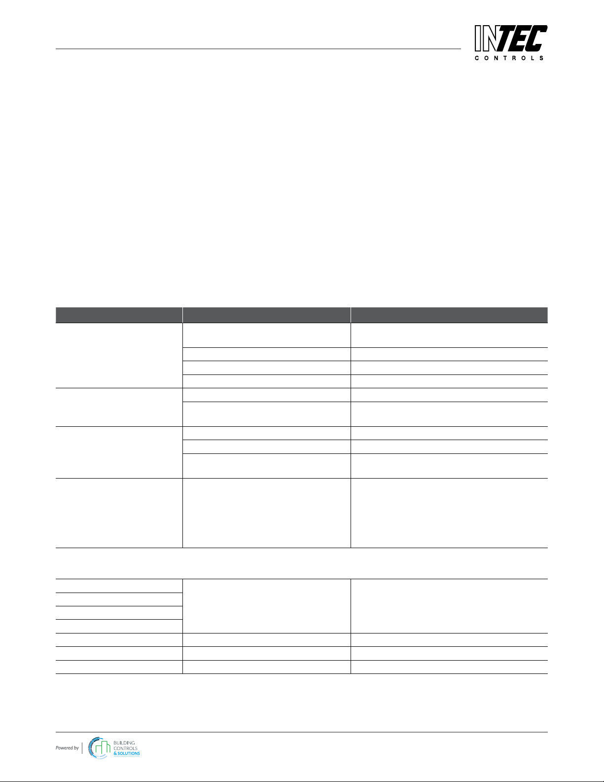
3.2 Terminal Connection (AT6)
• Open cover.
• Insert eld bus cable from above, cut and strip it.
• Connect it to the terminal (only 3-wire connection possible).
• For the 4-20 mA operating mode, please remove the built-in
500 ohm resistor between terminals 2 and 3.
4 Commissioning
Only trained technicians should perform the following when commissioning:
• Check for correct mounting location.
• Check if connection is correct.
• Check power voltage (for AT6).
• Install the Sensor Cartridge(s) if not already installed ex works.
• Check Sensor Cartridge connector for correct engagement.
• Calibration; note that new sensors are pre-calibrated at the factory.
Within the rst weeks after commissioning, there may be a deviation in the sensor behavior. Required instruments for
commissioning (calibration):
• Service Tool STL6 or
• DPT6 kit (DGC6 EasyConf Software incl. USB/RS-485 adapter)
• Calibration Gases:
• For toxic and oxygen sensors
• Zero gas bottle with synthetic air (20% oxygen, 80% nitrogen)
• Span gas bottle of target gas in the range of 30-90% of the measuring range. Rest is synthetic air.
• For combustible sensors
• Zero gas bottle with synthetic air (20% oxygen, 80% nitrogen)
• Span gas bottle of target gas in the range of 30-70% of the measuring range. Rest is synthetic air.
• For infrared CO2sensors
• Zero gas bottle with pure nitrogen 5.0 for zero-point calibration
• Span gas bottle with CO2in the range of 30-90% of the measuring range. Rest is synthetic air.
• Extraction set consisting of gas pressure regulator and ow meter
• Calibration adapter with tube; CONKIT-PG2.
Sensor Unit
AT6
3 2 1
4-20 mA
/ 2-10 V
GND
+24 V

INTEC Controls | 12700 Stowe Drive, Suite 100, Poway, CA 92064 | Ph: (858) 578.7887 & (888) GO.INTEC | inteccontrols.com
Specifications subject to change without notice. | Tox_D_1119, Ex_D_1119, CO2_D_0320 | USA 200413 | Page 7of 17
SC2-AT6 – UserManual
4.1 Installation of Sensor Cartridge
The Sensor Cartridges are provided already installed to the PG2 devices and capped to protect against dirt and
damage. Replacement sensors are available individually:
• Check gas type, range and calibration date of Sensor Cartridge.
• Dene installation place on the housing of the basic or remote sensor and break out knockouts.
• Tighten the Sensor Cartridge with M32 hexagon lock nut.
• Plug in the Sensor Cartridge at X2 or X3 of the sensor board. Observe plug polarity, the plug must engage.
4.2 Registration of the Sensor Cartridge
Registration and addressing of the eld bus can be read in the manual for the specic PG2 transmitter or controller.
5 Calibration
The service tool STL6 or DPT6 (DGC6 EasyConf software) are available for convenient on-site calibration. See their
respective datasheet.
A sensor exchange program is also available, consult your account executive.
Prior to calibration the Sensor Cartridge must be supplied with power voltage without interruption for
warm-up and stabilization. The warm-up time depends on the sensor element and is shown in the
following tables:
Gas type Formula Calibration with
replacement gas
(Sensitivity in %)
Warm-up
(h)
Flow rate
(ml/min)
Calibration interval
in months
Ammonia NH3- 18 300
See Specication
section later in this
document
Chlorine Cl2- 6 150
Hydrogen cyanide HCN - 6 300
Formaldehyde CH2O - 24 300
Carbon monoxide CO - 1 150
Ozone O3- 6 150
Sulfur dioxide SO2- 6 300
Hydrogen sulphide H2S - 6 150
Nitrogen dioxide NO2- 6 500
Oxygen (-A/-A2) O2- 1 150
Gas type Stabilization time
to spec (min)
Warm-up
(h)
Flow rate
(ml/min)
Calibration interval
in months
All (combustible) pellistor
sensors
60 24 150 See Specication
section later in this
document
Gas type Stabilization time
to spec (min)
Warm-up
(h)
Flow rate
(ml/min)
Calibration interval
in months
Carbon dioxide CO210 24 1500 See Specication
section later in this
document
Please observe proper handling procedures for compressed gas and test gas bottles.
Test gas can be toxic; never inhale it!
• Symptoms: Dizziness, headache and nausea.
• Procedure if exposed: Remove victim to fresh air at once, seek medical attention.

INTEC Controls | 12700 Stowe Drive, Suite 100, Poway, CA 92064 | Ph: (858) 578.7887 & (888) GO.INTEC | inteccontrols.com
Specifications subject to change without notice. | Tox_D_1119, Ex_D_1119, CO2_D_0320 | USA 200413 | Page 8of 17
SC2-AT6 – UserManual
5.1 Calibration Process
Prior to calibration, activate the mode “Special Mode” at the basic device via tool or software: only then the calibration
menu is enabled. During the special mode the basic device doesn’t issue alerts.
For visual illustrations, consult the online document “PolyGard2-Sensor-Calibration-Procedure.”
• Connect calibration adapter carefully to the sensor cartridge
• Connect calibration tool to the printed circuit board
• Select the Sensor Cartridge to be calibrated by selecting the gas type
Zero calibration
• For toxic, oxygen & combustible sensors
• Apply synthetic air (ow rate according to the table “calibration”, 1 bar ± 10%) to the Sensor Cartridge.
• For infrared CO2sensors
• Apply pure nitrogen 5.0 (ow rate according to the table “Calibration”, 1 bar ± 10%) to the Sensor Cartridge.
• The current zero oset and the oset value of the rst calibration is read with “Read”.
• When the value is stable, the new zero oset factor is calculated with “Calibration”.
The new oset factor is checked for plausibility and stored in the buer memory. The current measured value is output
with the new oset factor and the oset display is updated.
• With “Save” the new oset factor is written in the SC memory, only then the Zero calibration has been
successfully completed. If you exit the menu without pressing “Save”, the original oset data for the measured
value calculation will continue to be used.
• ALERT: With a zero reading > 10% of measuring range during the zero calibration, zero calibration is not
possible.
Gain calibration
• Enter test gas concentration:
• For toxic, oxygen and CO2, value between 30-90% of the measuring range.
• For combustibles, value between 30-70% of the measuring range.
• The current sensor element sensitivity is read with “Read”.
• Apply test gas (ow rate according to the table “Calibration”, 1 bar ± 10%) to the Sensor Cartridge.
• When the value is stable, the new gain factor is calculated with “Calibration”.
The new gain factor is checked for plausibility and stored in the buer memory. The current measured value is output
with the new gain factor and the sensor element sensibility is updated.
• With “Save” the new gain factor is written in the module’s memory, only then the gain calibration has been
successfully completed. If you exit the menu without pressing “Save”, the original gain data for the measured
value calculation will continue to be used.
Calibration will not be possible when the sensitivity of the sensor drops to 40% or lower; the Sensor
Cartridge must be replaced.

INTEC Controls | 12700 Stowe Drive, Suite 100, Poway, CA 92064 | Ph: (858) 578.7887 & (888) GO.INTEC | inteccontrols.com
Specifications subject to change without notice. | Tox_D_1119, Ex_D_1119, CO2_D_0320 | USA 200413 | Page 9of 17
SC2-AT6 – UserManual
5.2 Exchange of Sensor Cartridge
Instead of the on-site calibration, the used SC can be replaced simply and conveniently by a calibrated one.
The communication of the sensor cartridge to the sensor board is continuously monitored during
operation and results in an immediate error message on the gas controller in case of fault or interruption.
When replacing the sensor unit, the communication of the local bus is interrupted when unplugging the
SC connector which leads to an immediate triggering of the error message.
• Disconnect the SC connector from the printed circuit board (error message will be activated).
• Loosen the locknut.
• Remove used SC.
• Take calibrated SC out of the original packaging, check for gas type, measuring range and valid calibration
date.
• Insert the SC and re-tighten with lock nut.
• Insert the SC plug into the socket at the circuit board. Check plug for proper connection.
The local bus communication is automatically established and tested. At the same time the gas type and the
measuring range of the “new” SC are compared with the data stored in the circuit board. If they match and the
communication is correct, the error message will be automatically acknowledged in the Gas Controller.
The yellow LED of the circuit board ashes with a pulse of 1 sec. as long as the SC connector is disconnected
(communication error). After the local bus communication has been re-established and the conformity test has been
successful, the LED goes into ashing mode with 3 sec. pulse duration until the sensor’s warm-up time is over.
Apply a dened gas concentration on the sensor element with the help of the gas generator and check the
measurement signal at the analog output or at the relay outputs.
The entire cycle “Sensor Element > Sensor Cartridge > Local Bus > Sensor Board > Field Bus > Controller” is
observed and completed.
6 Inspection and Service
Inspection, service and calibration of the sensor should be done by trained technicians at regular intervals. We
therefore recommend concluding a service contract with INTEC Controls or one of their authorized partners.
According to EN 45544-4, inspection and service have to be executed at regular intervals. The maximum intervals
have to be determined and respected by the person responsible for the gas warning system according to the legal
requirements. INTEC Controls recommends employing the common inspection and service intervals as specied in
the general regulations of the gas measuring technique. The recommended calibration intervals depend on the sensor
element and can be read from the table “Calibration”. If there are dierent intervals, always observe the shortest one.
Inspections and services must be documented. The date for the next maintenance has to be axed to the sensor.
6.1 Inspection
Gas sensors should be controlled regularly by a competent person according to EN 45544-4. The following has to be
checked in particular:
• Maintenance/ calibration interval not exceeded.
• Visual inspection of the sensor including cable for damage etc.
• Remove dust deposits, especially at the gas inlet.
• The lter at the gas inlet has to be replaced if extremely dirty.

INTEC Controls | 12700 Stowe Drive, Suite 100, Poway, CA 92064 | Ph: (858) 578.7887 & (888) GO.INTEC | inteccontrols.com
Specifications subject to change without notice. | Tox_D_1119, Ex_D_1119, CO2_D_0320 | USA 200413 | Page 10 of 17
SC2-AT6 – UserManual
6.2 Service and Calibration
When performing the maintenance you have to do the calibration and the functional test, see chapter 5, in addition to
the inspection.
A xed calibration interval is stored for each sensor type.
SC2 Sensor heads:
If this interval is exceeded, a digital maintenance message is generated and forwarded. Performing the calibration
automatically deletes this message.
AT6 Sensor heads:
If this interval is exceeded, the current output of the AT6 goes to a xed 19 mA signal. For new devices (factory
calibration), the interval may be exceeded by a factor of 1.5.
After voltage recovery, there is a dened interruption of this message. This can be of use in order to employ the
device without the maintenance message for a few days (adjustable in system parameters -> error time, value
range> 1) until the calibration is repeated.
Performing the calibration automatically deletes this message.
INTEC Controls | 12700 Stowe Drive, Suite 100, Poway, CA 92064 | Ph: (858) 578.7887 & (888) GO.INTEC | inteccontrols.com
Specifications subject to change without notice. | Tox_D_1119, Ex_D_1119, CO2_D_0320 | USA 200413 | Page 11 of 17
SC2-AT6 – UserManual
7 Troubleshooting
7.1 Indicators at the SC2
The SC2 head does not have diagnostic indicators; messages are relayed from the attached PG2 devices.
7.2 Indicators at the AT6
The 4-20 mA output of the AT6 can be used as diagnostic indicators.
Output current
Restart: 1 mA
Device error: 2 mA
Tolerable negative sensor drift: 3-4 mA
Normal measurement mode: 4-20 mA
Tolerable overrange: 20-21 mA
Overrange error: >21 mA
Maintenance message: 19 mA
7.3 Printed Circuit Board
Trouble Cause Solution
Green LED isn’t on.
Power voltage not applied Measure tension at X4:
(16-28 V DC) Pin 1 (+) and 2 (-)
Polarity not correct at X4 Connect correctly
Connector X4 not plugged in Check the plug
Wire breakage Check the wiring
Green LED doesn’t ash.
PCB: no address Check PCB address, address correctly
PCB: no eld bus communication Check eld bus wiring, topology and
termination
No measured value at the
Tool or Controller
SC not or wrongly plugged in Check SC plug
SC not registered Register SC
SC gas type/measuring range doesn’t
match with registered ones
Check SC data<> registration data for
conformity
Message at the Tool /
Controller:
- 24 VDC voltage <range>
- 5 VDC voltage <range>
- Temp. <range>
- WatchDog triggered
Internal error Replace PCB
7.4 Sensor Cartridge (Messages at the Tool / Controller)
Measuring signal <range>
Internal error Replace SC
5 VDC voltage < range >
Temperature < range >
WatchDog triggered
SC Input 1 ≠ stored type Wrong SC type at input 1 Check SC at input 1, replace it
SC Input 2 ≠ stored type Wrong SC type at input 2 Check SC at input 2, replace it
SC Input 3 ≠ stored type Wrong SC type at input 3 Check SC at input 3, replace it

INTEC Controls | 12700 Stowe Drive, Suite 100, Poway, CA 92064 | Ph: (858) 578.7887 & (888) GO.INTEC | inteccontrols.com
Specifications subject to change without notice. | Tox_D_1119, Ex_D_1119, CO2_D_0320 | USA 200413 | Page 12 of 17
SC2-AT6 – UserManual
8 Cross-sensitivity Data
The cross sensitivity depends on the used transmitter type and can be read from the table Cross Sensitivity (see
section 9.4). Other gases can have an inuence on the sensitivity, too. The table does not claim to be complete. The
indicated sensitivity data are only standard values referring to new sensor elements.
9 Technical Data
All specications were collected under optimal test conditions.
We conrm compliance with the minimum requirements of the applicable standard.
9.1 SC2 (Sensor Cartridge)
Please check the SC2 datasheet for the latest specications. Available at:
http://inteccontrols.com/gas-detection/SC2.html
http://inteccontrols.com/gas-detection/SC2.pdf
9.2 AT6
Please check the AT6 datasheet for the latest specications. Available at:
http://inteccontrols.com/gas-detection/AT6.html
http://inteccontrols.com/gas-detection/AT6.pdf
INTEC Controls | 12700 Stowe Drive, Suite 100, Poway, CA 92064 | Ph: (858) 578.7887 & (888) GO.INTEC | inteccontrols.com
Specifications subject to change without notice. | Tox_D_1119, Ex_D_1119, CO2_D_0320 | USA 200413 | Page 13 of 17
SC2-AT6 – UserManual
9.3 Sensor Element
Sensor Cartridge (SC2 / AT6) Technical Data
INTEC Controls | 12700 Stowe Drive, Suite 100, Poway, CA 92064 | Ph: (858) 578.7887 & (888) GO.INTEC | inteccontrols.com
Specifications subject to change without notice. | USA 200303 | Page 3of 5
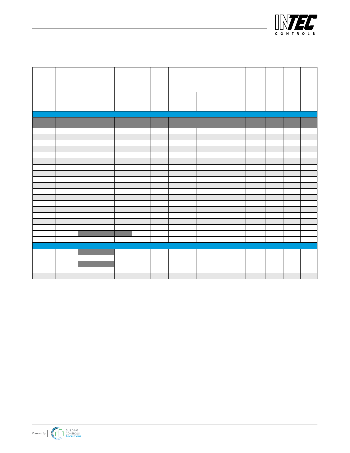
SC2
SENSOR PERFORMANCE TABLE
Part
Number
Molecular
Formula
Measuring
Range
Accuracy
Resolution
Repeatability
Response
Time
Zero Point
Variation
Long
Term
Drift
Working
Temperature
Humidity Range
(non-condensing)
Sensor Life
Expectancy1,
Normal Conditions
Relative Gas
Density
Mounting
Height
Calibration
Interval1
Zero
Gain
TOXIC GASES AND OXYGEN
ppm ± ppm ppm < ± %
sig.
t90 <
sec. ± ppm < % signal/
mo. °F % RH > mo. Air = 1 ft mo.
E1110-E CO 0-250 3 0.5 5 50 4 0.4 0.4 -4/149 10-95 72 0.97 5-6 12
E1110-F CO 0-300 3 0.5 5 50 4 0.4 0.4 -4/149 10-95 72 0.97 5-6 12
E1130-A NO20-10 0.5 0.1 2 25 0.2 1 2 -4/149 15-90 24 1.59 5-6 12
E1130-B NO20-20 0.5 0.1 2 25 0.2 1 2 -4/149 15-90 24 1.59 5-6 12
E1130-C NO20-30 0.5 0.1 2 25 0.2 1 2 -4/149 15-90 24 1.59 5-6 12
E1130-D NO20-500 20 2 2 25 0.2 1 2 -4/149 15-90 24 1.59 5-6 12
E1129-C NO 0-100 0.15 0.1 2 45 0.5 1 2 14/122 15-90 36 1.04 5-6 12
E1129-D NO 0-1000 20 2 2 45 24 1 2 14/122 15-90 36 1.04 5-6 12
E1125-C NH30-300 30 2 10 120 50 1 2 -22/122 15-90 24 0.59 Ceiling 12
E1125-D NH30-1000 30 4 10 120 50 1 2 -22/122 15-90 24 0.59 Ceiling 12
E1193-C Cl20-10 0.1 0.1 2 90 0.2 1 2 -4/122 15-90 24 2.4 Floor 6
E1183-C HCN 0-100 0.2 0.1 2 20 1 1 2 -4/122 15-90 24 0.93 Ceiling 6
E1189-C C2H40-200 1.0 0.3 1 60 4 1 3 -4/122 15-90 24 0.97 5-6 12
E1185-B CH2O 0-10 0.5 0.01 2 50 0.2 1 2 14/122 15-90 36 1.09 Floor 6
E1190-A O30-5 0.1 0.05 5 60 0.15 1 2 14/122 15-90 24 1.66 Floor 12
E1196-B SO20-20 0.2 0.2 2 20 0.1 1 2 14/122 15-90 24 2.26 Floor 12
E1197-A H2S 0-50 0.2 0.1 2 60 0.1 1 2 14/122 15-90 24 1.19 Floor 12
% Vol % Vol % Vol
E1195-A O20-25 0.5 0.05 -- 15 -- -- 0.3 -13/122 5-95 24 -- 5-6 6
INFRARED SENSORS
ppm ppm 100 -- -- -- 31/104 0-95 180 1.67 5-6 60
I1164-A CO20-2000 < 10%2-- -- 100 -- -- -- 31/104 0-95 180 1.67 5-6 60
% Vol % Vol
I1164-B CO20-5 < 10%2-- -- 100 -- -- -- 31/104 0-95 180 1.67 5-6 60
I1164-C CO20-2 < 10%2-- -- 100 -- -- -- 31/104 0-95 180 1.67 5-6 60
1Manufacturer-recommended calibration interval for normal environmental conditions
2of Reading

INTEC Controls | 12700 Stowe Drive, Suite 100, Poway, CA 92064 | Ph: (858) 578.7887 & (888) GO.INTEC | inteccontrols.com
Specifications subject to change without notice. | Tox_D_1119, Ex_D_1119, CO2_D_0320 | USA 200413 | Page 14 of 17
SC2-AT6 – UserManual
INTEC Controls | 12700 Stowe Drive, Suite 100, Poway, CA 92064 | Ph: (858) 578.7887 & (888) GO.INTEC | inteccontrols.com
Specifications subject to change without notice. | USA 200303 | Page 4of 5
SC2
SENSOR PERFORMANCE TABLE
Part
Number
Molecular
Formula
Measuring
Range
Accuracy
Resolution
Repeatability
Response
Time
Zero Point
Variation
Long
Term
Drift
Working
Temperature
Humidity Range
(non-condensing)
Sensor Life
Expectancy1,
Normal Conditions
Relative Gas
Density
Mounting
Height
Calibration
Interval1
Zero
Gain
COMBUSTIBLE GASES2
% LEL ± %LEL
(CH4)
%
(CH4)
< % sig.
(CH4)
t90 <
sec.
%
(CH4)
< % LEL /
mo. (CH4)°F % RH > mo. Air = 1 ft mo.
P3485-A C3H6O 0-100 1 0.2 1 15 0.5 0.3 1 -4/122 5-95 36 2.00 Floor 6
P3408-A NH30-100 1 0.2 1 15 0.5 0.3 1 -4/122 5-95 36 0.60 Ceiling 6
P3496-A vapors 0-100 1 0.2 1 15 0.5 0.3 1 -4/122 5-95 36 - - 6
P3460-A C4H10 0-100 1 0.2 1 15 0.5 0.3 1 -4/122 5-95 36 2.11 Floor 6
P3472-A C5H10 0-100 1 0.2 1 15 0.5 0.3 1 -4/122 5-95 36 - Floor 6
P3427-A C4H8O20-100 1 0.2 1 15 0.5 0.3 1 -4/122 5-95 36 3.04 Floor 6
P3425-A C2H5OH 0-100 1 0.2 1 15 0.5 0.3 1 -4/122 5-95 36 1.59 Floor 6
P3410-A C2H40-100 1 0.2 1 15 0.5 0.3 1 -4/122 5-95 36 0.98 Ceiling 6
P3491-A C7H16 0-100 1 0.2 1 15 0.5 0.3 1 -4/122 5-95 36 3.46 Floor 6
P3435-A C6H14 0-100 1 0.2 1 15 0.5 0.3 1 -4/122 5-95 36 2.98 Floor 6
P3476-A C5H12 0-100 1 0.2 1 15 0.5 0.3 1 -4/122 5-95 36 2.48 Floor 6
P3482-A C3H8O 0-100 1 0.2 1 15 0.5 0.3 1 -4/122 5-95 36 2.08 Floor 6
P3498-A JP8 0-100 1 0.2 1 15 0.5 0.3 1 -4/122 5-95 36 - - 6
P3402-A LPG 0-100 1 0.2 1 15 0.5 0.3 1 -4/122 5-95 36 - - 6
P3400-A CH40-100 1 0.2 1 15 0.5 0.3 1 -4/122 5-95 36 0.55 Ceiling 6
P3450-A CH3OH 0-100 1 0.2 1 15 0.5 0.3 1 -4/122 5-95 36 1.11 Floor 6
P3458-A C4H8O 0-100 1 0.2 1 15 0.5 0.3 1 -4/122 5-95 36 1.15 Floor 6
P3475-A C5H12 0-100 1 0.2 1 15 0.5 0.3 1 -4/122 5-95 36 2.49 Floor 6
P3480-A C3H80-100 1 0.2 1 15 0.5 0.3 1 -4/122 5-95 36 1.55 Floor 6
P3484-A C3H8O 0-100 1 0.2 1 15 0.5 0.3 1 -4/122 5-95 36 2.08 Floor 6
P3490-A C7H80-100 1 0.2 1 15 0.5 0.3 1 -4/122 5-95 36 3.18 Floor 6
P3440-A H20-100 1 0.2 1 15 0.5 0.3 1 -4/122 5-95 36 0.07 Ceiling 6
1Manufacturer-recommended calibration interval for normal environmental conditions
2 The sensitivity of Pellistor sensors can be inuenced by substances containing silicon compounds and even poisoned/destroyed by them.

INTEC Controls | 12700 Stowe Drive, Suite 100, Poway, CA 92064 | Ph: (858) 578.7887 & (888) GO.INTEC | inteccontrols.com
Specifications subject to change without notice. | Tox_D_1119, Ex_D_1119, CO2_D_0320 | USA 200413 | Page 15 of 17
SC2-AT6 – UserManual
9.4 Cross Sensitivity - Sensor Cartridge (SC2 / AT6) / Sensor Element
Ordering No.
Gas type
Alcohols
Chlorine, Cl2
Ethanol, C2H6O
Ethylene,
C2H4
Carbon
monoxide, CO
Carbon
dioxide, CO2
Sulfur
dioxide, SO2
Hydrogen
sulphide, H2S
Nitrogen
dioxide NO2
Nitrogen
monoxide, NO
SC2- / AT6- ppm ppm ppm ppm ppm ppm ppm ppm ppm ppm
E1125-AX NH310/0 100/0 100/0 200/0 5000/0 10/<10 10/<20 20/<2 20/0 1000/-10
E1125-BX NH310/0 100/0 100/0 200/0 5000/0 10/<12 10/<30 20/0 20/0 1000/-150
E1125-CX NH310/0 100/0 100/0 200/0 5000/0 10/<12 10/<30 20/0 20/0 1000/-150
E1125-DX NH310/0 100/0 100/0 200/0 5000/0 10/<12 10/<30 20/0 20/0 1000/-150
E1125-EX NH310/0 100/0 100/0 200/0 5000/0 10/<12 10/<30 20/0 20/0 1000/-150
E1193-XX2 Cl2300/0 5/0 20/20 35/0 300/0
E1183-XX2 HCN 100/0 100/2 20/38 15/25 5/-12 35/0 100/2
E1185-BX CH2O 10-18% 1-3%
E1110-XX2 CO 2/0 2000/5 5000/0 50/0.5 25/0 50/-1 50/8 100/20
E1190-XX2 O35/45/4 100/0 300/0 5/0 20/10 35/0 300/0
E1196-BX SO2100/0 100/1 10/0 100/-125 100/0 100/1
E1197-XX2 H2S 100/2 100/20 5/1 35/2 100/20
E1130-XX2 NO21/1 100/0 500/0 400/0 5000/0 30/-0.6 20/-25 50/0 1000/0
E1195-XX2 O25 Vol%/
Illustration: Gas concentration of interference gas / reaction of sensor
1 The table doesn’t claim to be complete. Other gases, too, can have an inuence on the sensitivity. The mentioned cross sensitivity data are only reference values valid for new sensors.
2 Cross sensitivities valid for all measuring ranges of the sensor.
INTEC Controls | 12700 Stowe Drive, Suite 100, Poway, CA 92064 | Ph: (858) 578.7887 & (888) GO.INTEC | inteccontrols.com
Specifications subject to change without notice. | Tox_D_1119, Ex_D_1119, CO2_D_0320 | USA 200413 | Page 16 of 17
SC2-AT6 – UserManual
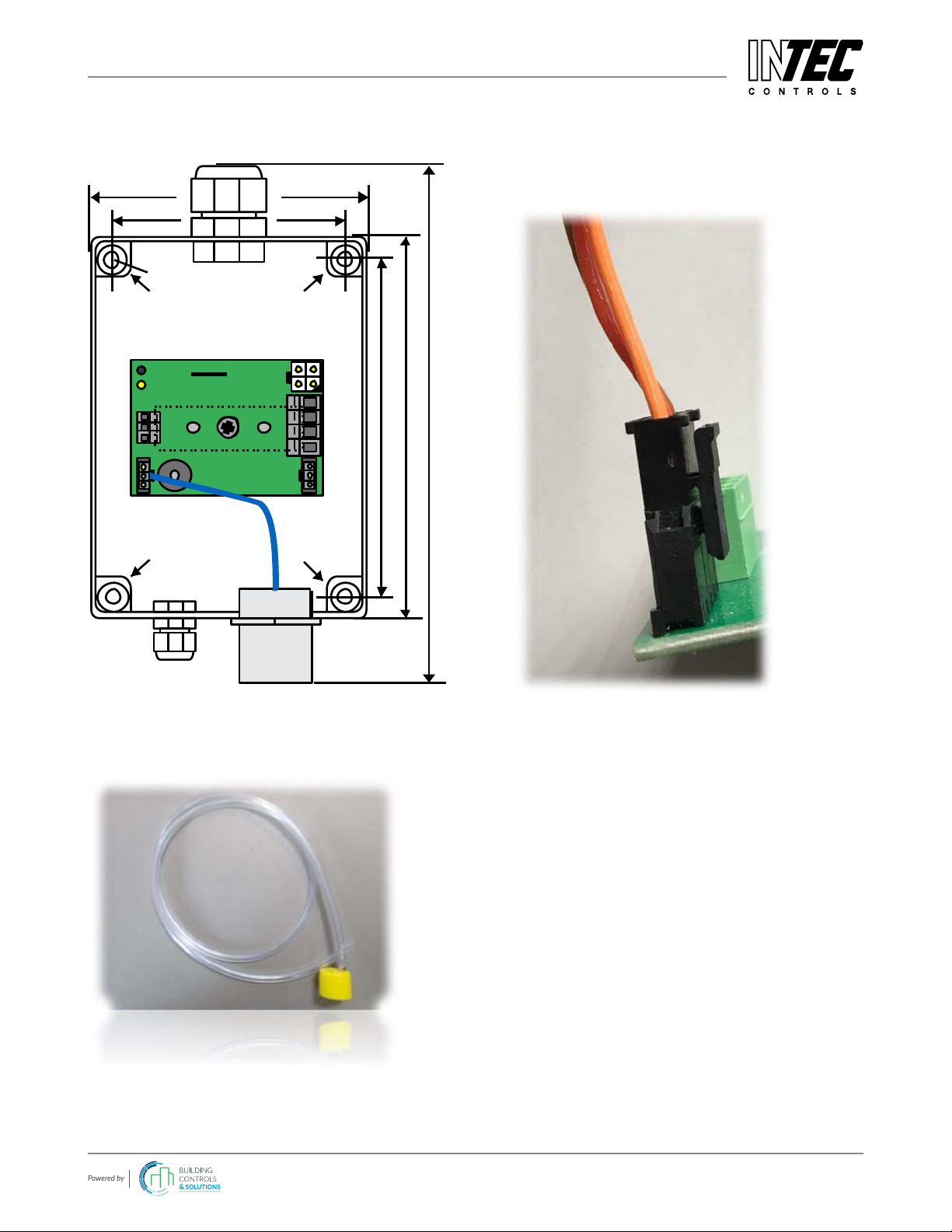
10 Figures
Fig. 1
Printed Circuit Board with Sensor Cartridge
Mounting
Mounting
Mounting
115 mm
X3
X2
X4
X7
130 mm
180 mm
Mounting
D = 4 mm
94 mm
79 mm
Fig. 3
SC2 connection to Printed Circuit Board
Fig. 2
Calibration adapter, CONKIT-PG2

INTEC Controls | 12700 Stowe Drive, Suite 100, Poway, CA 92064 | Ph: (858) 578.7887 & (888) GO.INTEC | inteccontrols.com
Specifications subject to change without notice. | Tox_D_1119, Ex_D_1119, CO2_D_0320 | USA 200413 | Page 17 of 17
SC2-AT6 – UserManual
11 Part Disposal
Observe all disposal codes.
12 Notes and General Information
It is important to read this user manual thoroughly and clearly in order to understand the information and instructions.
The SC2 / AT6 devices must be used within product specication capabilities. The appropriate operating and
maintenance instructions and recommendations must be followed.
Due to on-going product development, INTEC Controls reserves the right to change specications without notice. The
information contained herein is based upon data considered to be accurate. However, no guarantee is expressed or
implied regarding the accuracy of these data.
13 Intended Product Application
The SC2 / AT6 devices are designed and manufactured for control applications and air quality compliance in
commercial buildings and manufacturing plants.
13.1 Installers’ Responsibilities
It is the installer’s responsibility to ensure that all SC2 / AT6 devices are installed in compliance with all national and
local codes and OSHA requirements. Installation should be implemented only by technicians familiar with proper
installation techniques and with codes, standards and proper safety procedures for control installations and the latest
edition of the National Electrical Code (ANSI/NFPA70).
The equipotential bonding required (also e.g. secondary potential to earth) or grounding measures must be carried out
in accordance with the respective project requirements. It is important to ensure that no ground loops are formed to
avoid unwanted interference in the electronic measuring equipment.
It is also essential to follow strictly all instructions as provided in the user manual.
13.2 Maintenance
It is recommended to check the SC2 / AT6 devices regularly. Due to regular maintenance any performance deviations
may easily be corrected. Re-calibration and part replacement in the eld may be implemented by a qualied technician
and with the appropriate tools. Alternatively, the easily removable plug-in sensor cartridge with the sensor element may
be returned for service to INTEC Controls.
13.3 Limited Warranty
INTEC Controls warrants the SC2 / AT6 devices for a period of one (1) year from the date of shipment against defects
in material or workmanship. Should any evidence of defects in material or workmanship occur during the warranty
period, INTEC Controls will repair or replace the product at their own discretion, without charge. This warranty does
not apply to units that have been altered, had attempted repair, or been subject to abuse, accidental or otherwise. The
warranty also does not apply to units in which the sensor element has been overexposed or gas poisoned. The above
warranty is in lieu of all other express warranties, obligations or liabilities.
A pre-authorized RMA number is required for returns.
This warranty applies only to the SC2 / AT6 devices. INTEC Controls shall not be liable for any incidental or
consequential damages arising out of or related to the use of the SC2 / AT6 devices.
This manual suits for next models
1
Table of contents
Other Intec Accessories manuals


