PASCO PS-3224 User manual

Reference Guide
013-16057A
Wireless Optical Dissolved Oxygen Sensor
PS-3224
01/10/2019
*See the PASCO catalog or the PASCO web site for more information.
www.pasco.com
Equipment Included
Wireless Optical Dissolved Oxygen Sensor Micro USB Cable (1 meter)
Recommended Equipment Optical Dissolved Oxygen Metal Guard (PS-3605)
Required Item* Part Number*
PASCO Data Collection Software see www.pasco.com
Battery
LED
Bluetooth
LED
Micro USB Cable
Transparent Cover
Eye bolt
Probe
Power: Rechargeable Battery
or USB Cable
Connection:
Rubber Boot
(Covers
Sensor Cap*)
*NOTE: Avoid touching the end
of the Sensor Cap at all times.
Dimensions
Overall Length 22 cm Largest Diameter 6.7 cm
Probe Length 14.5 cm Probe Diameter 2.2 cm

PS-3224 Introduction
2
013-16057A
Introduction
The PASCO Wireless Optical Dissolved Oxygen Sensor is a versatile measuring device
that can connect to a computer wirelessly through Bluetooth (BLE) or physically through a
USB port. It includes a rechargeable battery and a Micro USB Cable. The sensor
measures the concentration and the saturation percentage of dissolved oxygen
molecules (O2) in aqueous solutions. The sensor also simultaneously measures
temperature and barometric pressure. The sensor is particularly useful in applications
related to ecological studies of aquatic environments. In the laboratory, students can
explore the effects of temperature, water movements, inorganic chemicals, organic
matter, and living organisms affect on levels of dissolved oxygen. In the field, students
can monitor dissolved oxygen as a part of ecological surveys of aqueous habitats,
including Biological Oxygen Demand (BOD) studies.
Note: The sensing element in the end of the probe can be replaced with the PS-3604
Optical Dissolved Oxygen Probe Sensor Cap described at the end of the manual.
SPARKvue allows the sensor to work with a mobile device such as a tablet or
smart-phone when the sensor is connected. PASCO Capstone will work on a PC or Mac.
The Optical Dissolved Oxygen Sensor has several advantages when compared to a
galvanic (electrochemical) dissolved oxygen sensor including the following:
* Barometric pressure is recorded and stored only when the sensor is initially connected via Bluetooth or USB.
Initial Step: Charge the Battery
• Connect the Cable: Remove the transparent cover from
the sensor. Use the included Micro USB Cable to
connect the micro USB port on the top of the sensor to a
USB port or USB charger such as the PASCO PS-2575
USB Single Port Charger. Charging begins
automatically. The charger circuit inside the sensor turns
itself off when the unit is fully charged. The battery status
LED will shine yellow as the battery is charging, and will
shine green when the battery is charged. The battery is
partially charged at the factory. Initial charging time may
be three hours or longer depending on the power source
and the condition of the battery.
Using the Sensor
The sensor is designed to work with PASCO data collection software to measure the concentration and saturation
percentage of dissolved oxygen.
ON/OFF Information
To turn the sensor on, remove the clear cover and then press the ON button. The status LEDs will blink. To turn the
sensor off, press and hold the ON button for a moment until the status LEDs stop blinking. The sensor puts itself to
sleep after one hour of inactivity if connected, and after several minutes if not connected.
•No warm up time •No calibration required
•No filling solution or electrode polishing •No flow dependency
•built-in temperature and barometric pressure compensation*
Cover
Sensor
Probe
Rubber
Boot
Battery
LED
Micro
USB Port
ON/OFF
Button
Device
ID
Bluetooth
LED

PS-3224 Introduction
3
013-16057A
Data Collection Software
See the PASCO web site at www.pasco.com/software for help in selecting the right PASCO software and to
check for the latest versions.
Software Help
•In Sparkvue, open the Main Menu and select “Help” for information about collecting, displaying, and analyzing
data.
•In the window that opens is the address of the web page for Help. Copy and paste the address into a web
browser program to open the Sparkvue User’s Guide web page.
•SPARKvue User’s Guide web page
.
PASCO Capstone SPARKvue
•Mac OS X •Mac OS X
•Windows •Windows
•iOS
•Android
•Chromebook
SPARKvue “Help” Window

Wireless Optical Dissolved Oxygen Sensor Set Up the Software
4013-16057A
•In PASCO Capstone, select PASCO Capstone Help from the Help menu,
or press F1.
LED Information
The Bluetooth and the Battery Status LEDs operate as follows:
For a wireless Bluetooth connection:
For a micro USB cable connection to a USB port:
For a micro USB cable connection to a USB charger:
*Logging: PASCO wireless sensors can either stream live data to a compatible device or log data (save it to the
sensor’s memory). The data can then be uploaded to the device for display and analysis at a later time. Logging
capability supports long-term or remote data collection while not connected to the device.
Note: The latest versions of SPARKvue and PASCO Capstone support logging. Check the PASCO Web page at
www.pasco.com/software for the latest software version.
Set Up the Software
SPARKvue Set Up
Connecting the Sensor to a Tablet or a Computer via Bluetooth
•For SPARKvue, select the
“Sensor Data” icon in the
Welcome Page.
•In the Sensor Data
Configuration window, look in
the “Connected Devices” list.
Select the correct address that
matches the Device ID XXX-XXX
number found on the sensor.
Select a measurement and then
select one of the “Quick Start
Experiments” Templates.
Bluetooth LED Status Battery LED Status
Red blink Ready to pair Red blink Low power
Green blink Connected
Yellow blink Logging*
Bluetooth LED Status Battery LED Status
OFF -- Yellow ON Charging
OFF -- Green ON Charged
Yellow blink Logging*
Bluetooth LED Status Battery LED Status
Red blink Ready to pair Yellow ON Charging
Green blink Connected Green ON Charged
Yellow blink Logging*

PS-3224 Set Up the Software
5
013-16057A
• SPARKvue Sensor Data Configuration Window:
•In the selected Template, click or touch “Start” to begin recording data.
Connecting the Sensor to a Computer with the Micro USB Cable
•Connect the micro end of the included Micro USB Cable into the micro USB port on the top of the sensor.
Connect the other end of the Micro USB Cable to a USB port on the computer, or into a powered USB hub
connected to the computer.
•In the SPARKvue Welcome Screen, select “Build New Experiment”.
.
Click or Touch to begin
recording data

Wireless Optical Dissolved Oxygen Sensor Set Up the Software
6013-16057A
•Select a Layout, and then select a data display.
•In the Data Display, Click “Select Measurement”. Select a measurement from the list under “Sensors”.
Select a Data
Display

PS-3224 Troubleshooting the Sensor
7
013-16057A
SPARKvue Collecting Data
•In SPARKvue, select the Start button to begin collecting data.
PASCO Capstone Set Up
Connecting the Sensor to a computing device (such as a computer) via Bluetooth
•For PASCO Capstone, select Hardware Setup in the Tools palette. In Hardware Setup the sensors are listed
in order by proximity to the device. Select the address that matches the Device ID XXX-XXX number on the
sensor.
Select a display in the main window or from the Display palette. In the display, use the <Select Measurement>
menu to pick a measurement to be shown.
Connecting the Sensor to a Computer with the Micro USB Cable
•Connect the micro end of the included Micro USB Cable into the micro USB port on the end of the sensor.
Connect the other end of the Micro USB Cable to a USB port on the computer, or into a powered USB hub
connected to the computer.
•In PASCO Capstone, select a display in the main window or from the Displays palette. In the display, use the
<Select Measurement> menus to pick the measurement to be shown.
PASCO Capstone Collecting Data
•In Capstone, select Record to begin recording data.
Troubleshooting the Sensor
•If the sensor loses Bluetooth connection and will not reconnect, try cycling the ON button. Press and briefly
hold the button until the status LEDs blink in sequence, and then release the button. Start the sensor in the
usual way.
•If the sensor stops communicating with the computer software or tablet application, try restarting the software
or application. If the problem remains, press and hold the ON button on the sensor for 10 seconds and then
release. Start the sensor in the usual way.
•Turn Bluetooth off and then back on. Retry.
Theory of Sensor Operation
Optical measurement methods that detect dissolved oxygen are based on the principle that dissolved oxygen
quenches both the lifetime and the intensity of the luminescence associated with certain chemical dyes. When
there is no dissolved oxygen present, the lifetime and intensity of the luminescence are at their maximum. The
luminescence of the dye and the amount of oxygen present have an approximately inverse proportionality.
The sensing element of the Optical Dissolved Oxygen Probe is inside the Sensor Cap. The sensing element has
two layers, The outer layer is a paint that acts as an oxygen permeable diffusion layer which allows oxygen
molecules to pass though while protecting the dye layer. The inner sensing layer is an immobilized polystyrene dye
layer that luminesces when excited with light of the correct wavelength. The probe measures dissolved oxygen by
emitting a blue light of the proper wavelength that causes the dye in the sensing layer to luminesce (glow) a red
color. Oxygen dissolved in the sample being tested continually passes through the diffusion layer to the dye layer,
affecting the luminescence lifetime and intensity of the dye. The sensor measures the lifetime of the luminescence
as it is affected by the oxygen with a photodiode and compares the reading to a reference.

Wireless Optical Dissolved Oxygen Sensor Theory of Sensor Operation
8013-16057A
.
The reference is a beam of red light emitted by a LED in the probe that reflects from the dye layer back to the
photodiode. The lifetime of the luminescence from excitation by the blue light is compared to that of the reference
value (red light) and a dissolved oxygen concentration is calculated by the sensor.
Optical and electrochemical dissolved oxygen probes determine the partial pressure of oxygen dissolved in the
sample being tested. The dissolved oxygen partial pressure is converted to concentration (mg/l) or saturation
percentage. The conversion from dissolved oxygen pressure to saturation percentage is done by dividing the
reading by 160, the pressure of oxygen in air at 760 millimeters (mm) of mercury (Hg) and then multiplying by
100%. For example, a measured dissolved oxygen pressure reading of 150 mm Hg would be converted to 93.8%
saturation (150/160 x 100%).
See the PASCO web site at www.pasco.com for more information.
Factors that Affect Dissolved Oxygen Measurement
Factors that affect dissolved oxygen measurement include temperature, barometric pressure, and salinity.
Temperature: The rate of diffusion of oxygen through the Sensor Cap changes with temperature (approximately
1.5% per degree celsius). The Optical Dissolved Oxygen Probe has a built-in thermistor, and the temperature
changes are compensated for by proprietary algorithms that use readings from the thermistor.
Barometric Pressure: The partial pressure of oxygen in a sample of air or water is not affected by barometric
pressure, but dissolved oxygen concentration in milligrams per liter is affected. The Optical Dissolved Oxygen
Probe has a built-in barometer sensor, and the reading from that device is used to determine the oxygen pressure
during calibration.
Salinity: As the salinity of water increases, its ability to dissolve oxygen decreases. (Note: The user will be able to
enter a value for the “salinity constant” in the data acquisition software.) For precise measurement of salinity, the
PS-2195 Salinity Sensor is recommended (see the web site at www.pasco.com).
Water Type Average Salinity
Fresh water <0.5 ppt*
Brackish water 0.5 to 30 ppt
Sea water 33 to 47 ppt
Saline water 30 to 50 ppt
Brine >50 ppt
Optical Dissolved Oxygen
Probe Sensing Layer (dye layer)
Sensor Cap with
Diffusion Layer
Photodiode and Light
Emitting Diodes (LEDs)
DO NOT TOUVH
Rubber O-ring
NOTE: Avoid touching
the Diffusion Layer or
the Sensing Layer

PS-3224 Theory of Sensor Operation
9
013-16057A
*Salinity is a unitless measurement determined from conductivity and temperature readings according to the
Practical Salinity Scale. Historically, salinity values determined with the Practical Salinity Scale were given the
designation “ppt” because these values were very close to those determined by the previously used method where
the mass of dissolved salts in a given mass of water (parts per thousand) were reported.
Probe Care and Maintenance
The sensing layer inside the Sensor Cap degrades over time due to bleaching caused by exposure to light, so the
Sensor Cap must be replaced periodically. It should also be replaced if it is cracked, scratched, or damaged. The
Sensor Cap is warranted for one year and may last much longer. The working life of a Sensor Cap may be
extended by keeping it clean and properly stored between uses. The replacement Probe Sensor Cap for the
Wireless Optical Dissolved Oxygen Sensor is model number PS-3604 (see www.pasco.com for more information).
NOTE: Do not remove the Sensor Cap except to replace it with a new cap.
To clean the Sensor Cap, rinse it with clean water and dry it with a lint free cloth. If necessary, use a mild detergent.
Do not use alcohols or other organic solvents that may deteriorate the oxygen permeable diffusion layer and the
sensing layer (dye layer). When changing the Sensor Cap, rinse the clear front surface of the nose-piece of the
probe with clean water and then dry the surface with a lint free cloth or lens tissue.
Optical Dissolved Oxygen Probe Attacking Liquids
Alcohols will remove the paint layer of the Sensor Cap. The following will remove the paint and dye layers of the
Sensor Cap and will attack the probe housing as well:
Storage
The Optical Dissolved Oxygen Probe should not be allowed to dry out. For storage, keep the Sensor Cap installed
on the probe. Moisten the small disk-shaped sponge that is in the end of the Rubber Boot (Sensor Cap Cover), and
place the end of the probe in the Rubber Boot so that the Sensor Cap is next to the moist sponge.
Do not store the probe directly in water since that would encourage algae growth on the probe.
Experiments
These are some of the experiments that can be done using the Optical Dissolved Oxygen Sensor.
•Photosynthesis, Respiration and Fermentation labs
•Monitoring Water Quality
•Measuring Net Primary Productivity
•Modeling Ecosystems
•Biochemical Oxygen Demand
Toluene Benzene Carbon tetrachloride Chloroform
Methylene chloride Acetone Methyl ethyl ketone Organic solvents

Wireless Optical Dissolved Oxygen Sensor Calibration: See www.pas-
10 013-16057A
Using the Wireless Optical Dissolved Oxygen Sensor Submerged
Typically, the probe of the Wireless Optical Dissolved Oxygen Sensor would sit
in a beaker of the liquid sample that is being measured. Alternately, the sensor
could be held by a clamp so that the end of the probe is immersed in the
container with the liquid sample. In addition, the sensor is designed to be
submerged for such uses as monitoring water quality in a pond or stream. Turn
the sensor on and pair it with the computing device. Set the sensor so that it will
record in logging mode. (The sensor will not connect wirelessly when
submerged.) To protect the sensor from the liquid sample, screw the transparent
cover firmly onto the top of the sensor. Make sure that the bottom edge of the
transparent cover touches the narrow lip. Remove but do not discard the Rubber
Boot before making a measurement. The sensor is not buoyant so it will sink if
dropped into the liquid sample. Therefore, attach a cable or cord to the eyebolt
at the top of the transparent cover before submerging the sensor. Be careful to
hold the cable or cord securely so that the sensor can be retrieved.
Using the Wireless Optical Dissolved Oxygen Sensor in Air
The Wireless Optical Dissolved Oxygen Sensor probe was specifically designed to be used in water. However,
reasonably good qualitative results may be obtained in air.
The optical dissolved oxygen probes are generally calibrated in 100% air-saturated water or in 'wet' air that is in a
100% relative humidity environment. In either case, the oxygen contribution to the partial pressure of the gas in
'wet' air or in solution is taken to be 20.9%. Given this, it is reasonable to use the probe in a gaseous environment
to measure the oxygen present. The sensor outputs a value labeled “O2 Gas Concentration”.
This value is calculated by taking the DO2 Saturation value from the sensor (100% in air-saturated water or 'wet'
air) and multiplying it by 0.209(20.9%), the assumed partial pressure contribution of O2 in air. For example, if the
DO2 Saturation value from the sensor is 80%, the calculated partial pressure contribution of O2 in air is 80% X
0.209 = 16.7% O2.
Best accuracy will be achieved in high humidity environments. Long term measurements in dry air are not
recommended as this will dry out the probe Sensor Cap and may affect future measurements with the probe.
NOTE: The probe should not be used in an environment with flammable, caustic or corrosive gases.
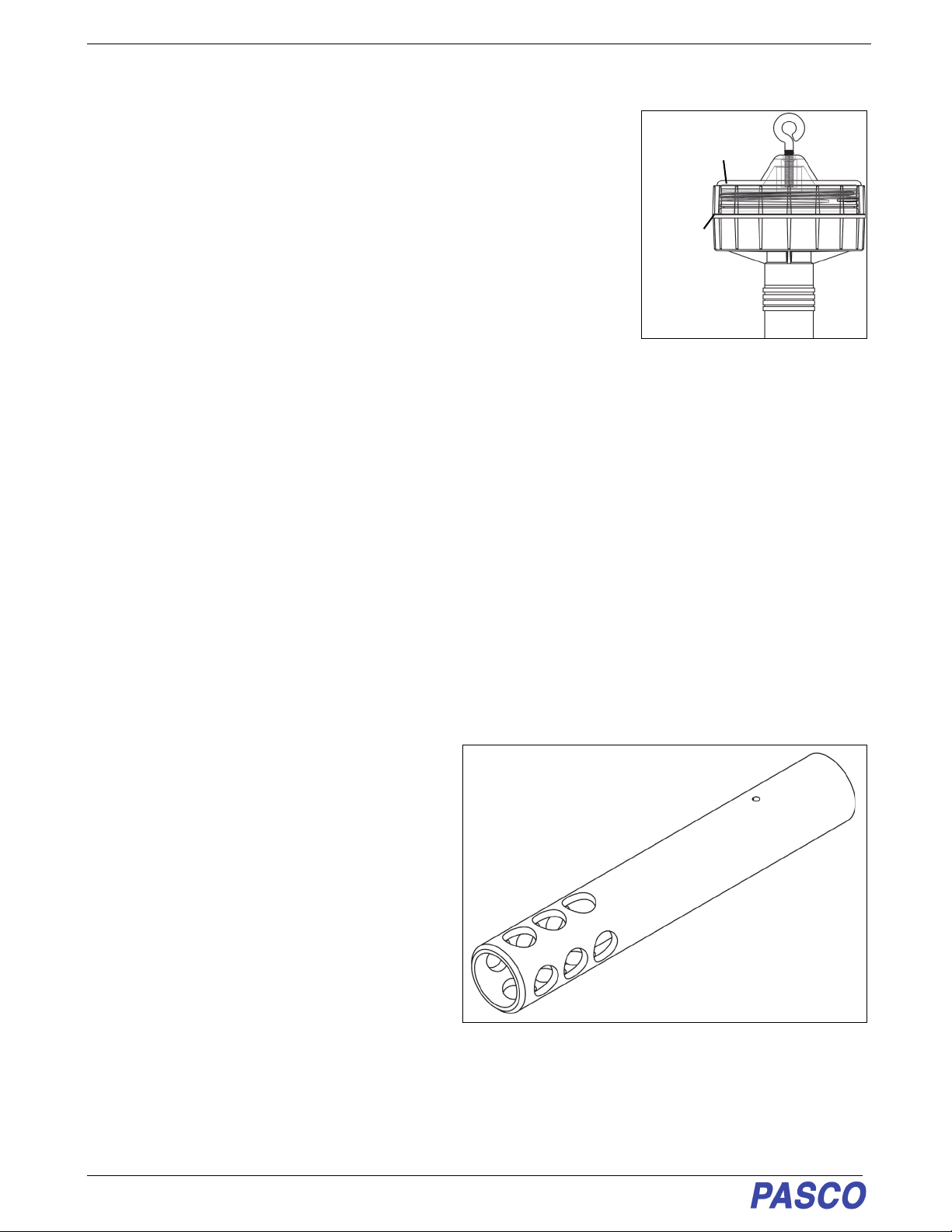
Accessory: Optical Dissolved Oxygen
Probe Guard (PS-3605)
The Wireless Optical Dissolved Oxygen Probe Guard
(PS-3605) is designed to thread onto the probe to
protect the Sensor Cap. It also enables the probe to
sink more rapidly when the probe is immersed in
water.
NOTE: Do not use any tool to thread the Probe Guard
onto the probe. Avoid touching the end of the Sensor
Cap at all times.
Calibration: See
www.pasco.com/calibration
The Wireless Optical Dissolved Oxygen Sensor is calibrated at the factory and does not need to be re-calibrated
under most circumstances. However, if the Sensor Cap is replaced with a new Sensor Cap (PS-3604), then the
Sensor Cap Calibration Code Coefficients (included with the new Sensor Cap) will need to be entered into the
sensor using the PASCO data collection software (PASCO Capstone or SPARKvue). The sensor will then need to
be re-calibrated. (See Replacement Sensor Cap Calibration.)
Narrow
Lip
Transparent
Cover
Wireless Optical Dissolved
Oxygen Probe Guard

PS-3224 Calibration: See www.pasco.com/calibration
11
013-16057A
For a one-point calibration, you will need one “known standard” with 100% dissolved oxygen saturation.
For a two-point calibration, you will need two “known standards”; one with 100% dissolved oxygen saturation, and
one with 0% dissolved oxygen saturation.
Known Standards (100% dissolved oxygen saturation and 0% dissolved oxygen saturation)
One method for a known standard with 100% dissolved oxygen saturation is to use water-saturated air. Moisten the
sponge inside the end of the Probe Cover (Rubber Boot) with water, and then put the probe into the Probe Cover
for about fifteen minutes. WARNING: Don’t calibrate the sensor if the end of the Sensor Cap is under pressure.
Therefore, do not push the Probe into the Rubber Boot so far that it compresses the water-moistened sponge.
A second method for a known standard with 100% dissolved oxygen saturation is to use air-saturated water.
Connect an air-stone to an air pump, and put the air-stone into water. Allow the air-stone and air pump to run for 10
minutes to make sure that the water is completely saturated.
To make a known standard with 0% dissolved oxygen saturation, dissolve enough sodium sulfite, sodium bisulfite,
or potassium sulfite in 150 milliliters of distilled water such that a small amount of sodium sulfite remains
undissolved in the bottom of the beaker. WARNING: Use the same standard lab safety procedures for handling
sulfite compounds as for handling any chemical compound.
PASCO Capstone Calibration. Remember, see www/pasco.com/calibration
Capstone Calibration Steps
•Place the Wireless Optical Dissolved Oxygen Sensor into your known standard for 100% dissolved oxygen
saturation (for example, moisten the sponge inside the end of the Probe Cover (Rubber Boot) with water, and
then put the probe into the Probe Cover for about fifteen minutes,)
•In PASCO Capstone, click the Calibration icon in the Tools palette to open the Calibration panel.
1. The first step in the Calibration panel says
“Choose the type of measurement you would like
to calibrate:” The default for the sensor is “Satura-
tion”. Click “Next”.
2. The second step says “Choose the probes you
would like to calibrate now:”.The, Wireless Optical
Dissolved Oxygen Sensor is automatically
selected (if the default measurement is kept).
Move to the third step.
3. The third step says “Choose the type of calibration
you would like to perform:” Select “One Standard
(1 point slope)”. Click “Next”.
4. NOTE: The first point of calibration is already set,
so the fourth step says (Calibrate the second
point:)

Wireless Optical Dissolved Oxygen Sensor Calibration: See www.pas-
12 013-16057A
5. Wait a few moments until the readings in “Current Value” stabilize and then click “Set Current Value to
Standard Value”. After that, click “Next”.
6. The fifth step says to “Review your calibration and accept:” Click “Finish” to accept, or click “Back” to return to
the previous step.
•When you are finished, click the Calibration icon in the Tools palette to close the Calibration panel.
Notes About Calibration Using Capstone
•Do not calibrate the Wireless Optical Dissolved Oxygen Sensor while another different type of sensor is being
used. If you are using two or more different sensors, calibrate the Wireless Optical Dissolved Oxygen Sensor
by itself first, and then connect (pair) and calibrate the other sensor(s) if necessary.
•During the calibration process, if you click “Calibrate first point” or “Calibrate second point” and then click
“Cancel”, the sensor will be restored to its previous calibration.
•The “Standard Value” text areas cannot be edited because the Optical Dissolved Oxygen Sensor is being
calibrated for Saturation.
Capstone Salinity Constant
•Because salinity is one of the factors that can affect dissolved oxygen measurement, a value for salinity can be
entered in the Calibration panel.
1. In Capstone, click the Calibration icon in the Tools palette to open the Calibration panel.
2. In the first step it says “Choose the type of
measurement you would like to calibrate:”,
Click the down arrow in the “Saturation” menu
and then select “Wireless Optical Dissolved
Oxygen Sensor: Set Constant” as the type of
measurement.After “Wireless Optical
Dissolved Oxygen Sensor Set Constant” is
selected click “Next”.

PS-3224 Calibration: See www.pasco.com/calibration
13
013-16057A
3. In the second step it says “Edit the value:”.Refer to
the table of salinity values (shown previously.) and
enter the correct value in the text area. Click
“Finish”.
4. Click the Calibration icon in the Tools palette to close
the Calibration panel
SPARKvue Calibration. Remember, see
www/pasco.com/calibration
SPARKvue Calibration Steps
•Place the Wireless Optical Dissolved Oxygen Sensor into your known standard for 100% dissolved oxygen
saturation.
1. In SPARKvue, touch or click “Sensor Data” in the Welcome Screen, and connect to the Wireless Optical Dis-
solved Oxygen Sensor.
2. In the SPARKvue “Sensor
Data Configuration” window,
check that the “DO2
Concentration” measurement
and Temperature
measurement are
checkmarked.
3. In the “Templates” window
next to the “Sensor Data
Configuration” window, click
one of the Data Display
“Templates” (Graph, Table
and Graph or Digits) to open a data display.

Wireless Optical Dissolved Oxygen Sensor Calibration: See www.pas-
14 013-16057A
4. In the new Data Display, touch/click the Hardware Setup icon to open the “Configure Sensors and
Measurements” window.
5. In the “Configure sensors and measurements” window, “D02 Saturation” is the default choice for calibration.
Touch or Click the Calibration icon to open the “Calibrate Sensor: Select Measurement” window
.
Touch or Click
the Hardware
Setup Icon
Calibration Icon

PS-3224 Calibration: See www.pasco.com/calibration
15
013-16057A
6. In the “Calibrate Sensor: Select Measurement” window, DO2 Saturation (%) is the default measurement. “1
point (Adjust Slope Only) is the default Calibration Type. Click or touch “Continue” to open the “Calibrate
Sensor: Enter Values” window.
7. In the “Calibrate Sensor:
Enter Values” window,
“Calibration Point 2” is the
default selection with the
“Standard Value: 100.0000”
and the “Sensor Value:.
panel. NOTE: that the
“Sensor Value” panel will
show the number coming
from the Sensor.
8. When the Sensor Value
stabilizes, click or touch “Set
Calibration”’
9. Click or touch “New
Calibration” to see the values
of the Slope and Offset.
10. Click or touch “OK” to return
to the “Configure Sensors
and measurements” panel.
Live DO2 Saturation value
coming from the Sensor.

Wireless Optical Dissolved Oxygen Sensor Calibration: See www.pas-
16 013-16057A
SPARKvue Salinity Constant
•Because salinity is one of the factors that can affect dissolved oxygen measurement, a value for salinity can be
entered in the Edit Sensor Properties window.
1. Click the “right arrow” in the “Configure
sensors and measurements” panel to
close the panel and return to the data dis-
play.
2. In the data display, click the up arrow
menu icon in the Live Data Bar to open
the menu that shows “Configure Sensor”
and “Edit Data Properties”.
3. Touch or click the “Configure Sensor” choice in the Live Data Bar menu to open the “Edit Sensor Properties:”
window.
Click or
Touch to
close the
panel.
Click or Touch to
open the menu.
Click or Touch
“Configure Sensor”
Live Data Bar

PS-3224 Calibration: See www.pasco.com/calibration
17
013-16057A
4. In the “Edit Sensor
Properties:” window in the
“Salinity Constant” panel,
highlight the value next to
“Salinity Constant”. Next,
enter a correct salinity value
from the table of salinity
values shown previously.
5. Touch or click “Set Salinity
Constant” and then touch or
click “Done” to close the
window.
Replacing the Sensor
Cap
The sensing layer inside the
Sensor Cap degrades over time
due to bleaching caused by
exposure to light, so the Sensor
Cap must be replaced
periodically. It should also be
replaced if it is cracked,
scratched, or damaged. The
Sensor Cap is warranted for one
year and may last much longer.
The working life of a Sensor Cap
may be extended by keeping it
clean and properly stored
between uses.
The PS-3604 Replacement Sensor Cap is designed for the PS-3224Wireless Optical Dissolved Oxygen Sensor
(see www.pasco.com for more information). The Replacement Sensor Cap includes the following:
• Replacement Sensor Cap
• Rubber O-Ring
•Page of “Sensor Calibration Coefficients for Cap Replacement (please see the example).
Enter salinity values here

Wireless Optical Dissolved Oxygen Sensor Replacement Sensor Cap Calibra-
18 013-16057A
Replace the Sensor Cap
To remove the Sensor Cap, first remove the Rubber Boot from the bottom of the probe. Grasp the plastic section of
the Probe body in one hand and turn the metal Sensor Cap counterclockwise to loosen it. DO NOT USE A TOOL
to unscrew the Sensor Cap. If the Rubber O-ring is damaged, replace it with the O-ring included with the
Replacement Sensor Cap. Put the Replacement Sensor Cap onto the end of the probe and turn it clockwise until it
meets the metal part of the probe body. DO NOT USE A TOOL to install the new Sensor Cap. NOTE: The Sensor
Cap may be quite difficult to remove and replace. Make sure that your hands, the probe and the sensor cap are dry
and clean.
Replacement Sensor Cap Calibration
After a new Replacement Sensor Cap (PS-3604) is placed on the Optical Dissolved Oxygen probe, there are two
parts to the Sensor Cap Calibration process. First, enter the Sensor Calibration Coefficients into the software
(PASCO Capstone or SPARKvue). Second, do a one-point or two-point calibration as described previously.
•The Replacement Sensor Cap includes a page with the Sensor Calibration Coefficients for Cap Replacement
(please see the example page).
Optical Dissolved Oxygen
Probe
Sensor Cap
Rubber O-ring
NOTE: DO NOT
TOUCH
Metal Probe
Body
Sensor Calibration Coefficients for Cap Replacement
SN?YL0118072007
Sensor Calibration Coefficients
K0?-0.0002
K1?0.2814
K2: 0.0423
K3?-0.0015
K4?0
K5?0.0133997
K6?0.0000903
K7?30.1
K8?1.881343
K9?BA8D
Please keep it for future reference
Example Numbers:
Do not use these
numbers for
calibration.
SERIAL NUMBER for the
Coefficients.
Use it as a reference if you
contact Technical Support
Example page
of Sensor
Calibration
Coefficients

PS-3224 Replacement Sensor Cap Calibration
19
013-16057A
Capstone Calibration Code Coefficients:
1. With the sensor “paired” (connected to the computing device) use the data collection software to enter the Cal-
ibration Code Coefficients (ten number) for the replacement Sensor Cap into the sensor.
2. In the Hardware Setup panel, click the “Prop-
erties” icon ( ) in the lower right corner to
open the Sensor Properties window.
3. In the “Properties” window, touch or click “Cap
Coefficients” to select the text panel.
4. Next, enter the ten numbers from the sheet
with the Calibration Code Coefficients for Cap
Replacement as a list of 10 numbers sepa-
rated by spaces.
•NOTE: Enter the numbers with a space
between each number.
•NOTE: Enter the numbers exactly as they
appear on the sheet with the Calibration Code
Coefficients for Cap Replacement including
negative signs, decimal points, and other
characters.
5. When finished, touch or click “OK” to close the
Properties window.
SUCCESS
A message appears if the Cap Coefficient has been successfully set.
ERROR MESSAGES
If the message titled “Cap Coefficients failure” appears, it will include a description of the problem.
One error message is “Invalid checksum”. Make sure that the 10 numbers exactly match the ones on the
Calibration Code Coefficients for Cap Replacement sheet. Another message is “Coefficients must be a list of 10
numbers separated by spaces”. Re-enter the numbers with a space between each one.
6. After successfully entering the Calibration Coefficients, perform a one-point or a two-point calibration as
described previously.

Wireless Optical Dissolved Oxygen Sensor Replacement Sensor Cap Calibra-
20 013-16057A
SPARKvue Calibration Code Coefficients
1. In SPARKvue, click or touch the Hardware Setup panel in the data display to open the “Con-
figure Sensors and measurements” window.
2. Click or touch the “Configure Sensor Icon” to open the Edit Sensor Properties Window.
3. In the area next to “Cap Coefficient” enter the enter the ten numbers from the sheet with the Calibration Code
Coefficients for Cap Replacement as a list of 10 numbers separated by spaces.
•NOTE: Enter the numbers with a space between each number.
•NOTE: Enter the numbers in the text area exactly as they appear on the sheet with the Calibration Code
Coefficients for Cap Replacement including negative signs, decimal points, and other characters.
4. Touch or Click “Set Cap Coefficient” to save the coefficients. Click or touch “Done” to close the window.
5. A small window opens to confirm that the procedure was successful.
Configure
Sensor icon
Enter Cap
Coefficients here
Other manuals for PS-3224
2
Table of contents
Other PASCO Accessories manuals

PASCO
PASCO PS-3217 Guide

PASCO
PASCO PS-3204 User manual

PASCO
PASCO PS-3221 User manual

PASCO
PASCO PS-3218 User manual

PASCO
PASCO CI-6538 User manual

PASCO
PASCO PS-2102 User manual

PASCO
PASCO PS-3322 User manual

PASCO
PASCO PASPort PS-2129 User manual

PASCO
PASCO CI-6561 User manual

PASCO
PASCO Motion Sensor II CI-6742A User manual

PASCO
PASCO Pasport PS-2140 User manual

PASCO
PASCO CI-6504A User manual

PASCO
PASCO PS-3219 User manual

PASCO
PASCO CI-6537 User manual

PASCO
PASCO Motion Sensor II User manual

PASCO
PASCO PASPORT PS-2124A User manual

PASCO
PASCO PS-3213 User manual

PASCO
PASCO PAS Port PS-2186 User manual

PASCO
PASCO PS-3208 Guide

PASCO
PASCO PASPORT PS-2104 User manual