Intec Car Vision CVD650LCD-A User manual
Car Vision® System
Utilizing the
CVD650LCD
So ware Version 1.0.5 ESG
CVD650LCD-A
So ware Version 1.0.5A ESG
System User’s Guide
© INTEC Video Systems, Inc. Revision F - August 2022

Table of Contents
General Information 4
Introduction 4
What This Manual Covers 4
Important Information 4
Certifi cates of Compliance 4
Warnings and Cautions 5
Getting Started 6
Turning On Your Car Vision® System 6
Verifying Proper Image Orientation 6
How to Change Your Image Orientation 6
Adjusting the Screen Brightness 6
Single or Dual Camera System Applications Using a CVS100 or CVS102 Series Controller 7
Becoming Familiar with your CVR100 Remote 7
Button Label and Function 7
Navigating the On Screen Display Menu (CVS100 or CVS102) 8
Help Screen 8
User Menu 8
Installer Menu 9
Advanced Features (CVS100 or CVS102) 10
External Video Input / Output 10
Integrated Active Object Detection (Radar) 10
One to fi ve Camera System Applications Using a CVS500 Series Controller 11
Becoming Familiar with your CVR500 Remote 11
Button Label and Function 11
Navigating the On Screen Display Menu (CVS500) 12
Help Screen 12
User Menu 12
Installer Menu 13
Advanced Features (CVS500) 16
External Video Input 16
Programmable Video / Audio Output 16
Naming Input and Radar Positions 16
Multi Display Camera View 17
Triggered Multi Display Camera View 17
Programmable Auto Camera Cycle 18
Programmable External Auto Camera Cycle 18
Integrated Active Object Detection (Radar) 19
Page 2

Table of Contents
Additional Features (CVS500) 20
Trigger Sequencing 20
Turn Signal Triggering 20
Momentary Rear Camera Override 20
Maintenance and Troubleshooting 21
Preventative Maintenance 21
Status LED’s and Fuses (CVS100 or CVS102) 22
Status LED’s and Fuses (CVS500) 23
Troubleshooting 23
Service and Warranty 24
How to get Service 24
Warranty Policy 25
Locations 25
Page 3

General Information
Introduction
Thank you for selecting an INTEC Car Vision® System. Before using your system, please be sure to read and understand
these instructions carefully. If you have any questions or concerns, please do not hesitate to contact us toll free at
800-468-3254 (west) or 800-522-5989 (east). You may also reach us via e-mail at info@intecvideo.com
What this Manual Covers
This manual covers the information necessary for the proper use of your Car Vision® Mobile Video Safety System.
Information on installing your system can be found on the Quick Installation Guides provided with your equipment or by
visiting www.intecvideo.com/installation.html
Important Information
Please read this guide carefully before use.
There are no user serviceable parts inside the system components. All service must be completed by authorized service
personnel only. Please refer to the Warranty section described later in this manual.
Always use the proper tools, wear protective clothing and take necessary precautions when working around electricity to
prevent electrical shock.
Use only INTEC specifi ed and provided brackets and cables to connect the components of the system. Use of other than
INTEC specifi ed and supplied brackets and cabling could be dangerous and result in damage to the system components
and void the warranty.
Use only INTEC specifi ed and supplied accessories and options when upgrading your system.
Operating the camera system on too low or too high a voltage may damage the system.
Always confi rm the view provided by the camera is adequate for your needs prior to vehicle use. Adjustments to the
camera viewing angle should be made before use, if necessary.
Most states have laws pertaining to motor vehicles equipped with a video display within the driver’s fi eld of vision, either
directly or indirectly, unless the video display is used in conjunction with a back up safety camera to monitor the blind
spots around the vehicle. INTEC’s products are specifi cally designed to enhance vehicle safety. Use of an INTEC display
to view video in any manner other than intended requires installation in accordance with your state laws.
Do NOT let the Car Vision® System distract you from driving safely.
Certifi cates of Compliance
2002 / 95 / EC Complies with Part
15 of the FCC Rules
e13
Page 4

Warnings and Cautions
Warnings
Do NOT attempt to connect other electrical devices to the power wire harness of the Car Vision® System as this can
cause an over current situation which can lead to electrical shock or fi re.
If at any time you see or smell smoke coming from the Car Vision® System, stop driving, exit the vehicle and disconnect
main power. Check the system and remove any damaged components before you resume normal vehicle operation.
Do NOT attach the wiring to any moving parts, across sharp edges or close to heat sources as this may cause shorting of
the wires and may lead to a fi re or electrical shock.
When installing the system be sure to use only INTEC supplied brackets. The Car Vision® camera must be insulated from
the vehicle body. The supplied camera bracket provides the required insulation. Failure to do so could result in a fi re and
lead to property damage or personal injury.
Do NOT install the camera in any area that allows it to extend out past the vehicle as this can cause injury if it were to
come in contact with people walking around the vehicle.
Never use fuses of a larger rating than those supplied with your Car Vision® System. Use of larger rated fuses can cause
excessive current through the system if a short occurs and could lead to a fi re.
Confi rm that the orientation of the image on the display is proper. Rear facing cameras should yield a mirror image, where
items on the left of the vehicle appear on the left side of the monitor.
Cautions
Before you begin driving, be sure the display controls are adjusted properly. This will avoid unnecessary distractions while
driving.
When installing the camera system be certain that all items are secure. Items that are not secure or mounted in an
unstable manner can come loose and cause damage or personal injury.
Do NOT attempt to open or service your equipment. Removal of the product enclosure can lead to electrical shock. No
user serviceable parts inside.
You should not attempt to make any adjustments to the Car Vision® System while driving as this can lead to an accident.
Only make adjustments when the vehicle is stopped.
Keep the Car Vision® System clean and free from dirt, snow and ice. If the camera glass or display panel becomes dirty,
clean them before use. If they are covered with snow and/or ice, it should be cleared off before use. Failure to do so could
lead to an accident.
When running a cable from the exterior to the interior of a vehicle, care needs to be taken to seal the entry point. Failure
to do so could allow in exhaust fumes, other toxic gases or water.
Page 5

Getting Started
Turning On Your Car Vision® System
Your Car Vision® System, when properly installed, is activated automatically when power is applied to the trigger wire(s),
typically reverse, but it can also be activated manually via the ON/SB button on the remote. Note: The vehicle’s ignition
switch must be on or the vehicle must be running for the system to operate.
When activated automatically (triggered) by placing the vehicle in reverse the system will turn on providing you with a
clear image of what is behind your vehicle. Additionally, an on screen distance grid (pictured below) will appear. The
distance grid is for reference only and does not equate to any specifi c measurement.
Verifying Proper Image Orientation
The orientation of the image displayed is critical to safe vehicle operation. An object on the right side of your vehicle needs
to be seen on the right side of the displayed image.
Generally, if your display is facing rearwards, you would want a Mirror image displayed from a camera facing rearward
and a True image displayed from a camera facing forward. The image orientation of a camera on the right or left side of
the vehicle will depend on how far off of center they are facing.
For example; a camera mounted on the right or left side of the vehicle facing straight out would usually require a True
image be displayed. But angle the camera towards the rear and a Mirror image may be required. Always confi rm proper
image orientation before operating your vehicle.
How to Change Your Displayed Image Orientation
INTEC’s CVC Series cameras are set as default at the factory to display a Mirror image when used with our CVD Series
displays. Should you need to change the default image, you can do so through the displays on screen Installers Menu.
See page 9 for system applications using a CVS100 or CVS102 series controller or page 13 for system applications using
the CVS500 series controller for additional information. Additionally, a number of our CVC series cameras are equipped
with image reversal switches, refer to your cameras quick installation guide for additional information.
Adjusting the Screen Brightness
Adjustments can be made to the LCD screen intensity level by pressing the Up or Down Arrow buttons on the remote
control. NOTE: If your Dimmer function is set to AUTO your screen brightness will revert back to its original setting when
the power is cycled.
Page 6
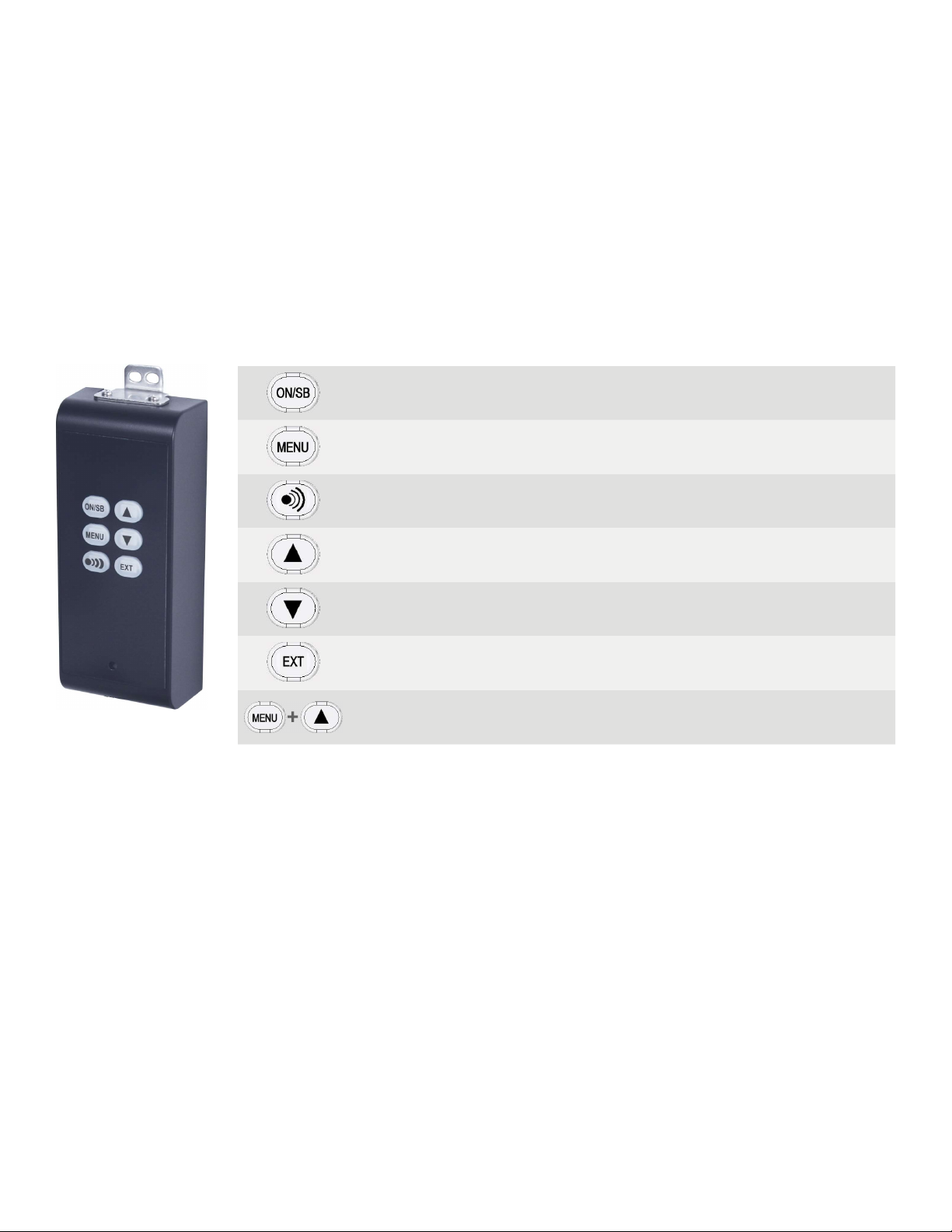
Becoming Familiar with your CVR100 Remote
All adjustments to your Car Vision® system are made via the CVR100 remote control. For your convenience the buttons
on the remote are backlit to aid in use under low light conditions. The CVR100 remote also includes a speaker for audio
equipped systems and serves to provide an audible alert when the system is used in conjunction with our active radar
component.
Button Label and Function
Manually turns the display on or places it in standby.
Accesses the on-screen users menu.
Scrolls through the menu items.
Adjusts the radar audible alert volume between three available preset levels.
(Active when used with a compatible radar system)
Increases screen brightness.
Increases the value of a menu item.
Decreases screen brightness.
Decreases the value of a menu item.
Selects the external video input. (EXT must be set to ON in the Installer’s
Menu before EXT can be selected).
Press both buttons simultaneously to access the Installer Menu.
Page 7
Single or Dual Camera System Applications using a CVS100 or
CVS102 Series Controller
Page 8
Navigating the On Screen Display Menu (CVS100 or CVS102)
There are three menus available when using a CVS100 or CVS102 controller, the Help Menu, the User Menu and the
Installer Menu. The Help Menu explains the buttons used to navigate the menu. The User Menu allows you to adjust
menu items associated with the image such as brightness, contrast, etc... The installer Menu allows you to adjust the
more advanced features of your system such as image orientation. Navigating the menu is done via the CVR100 Remote
Control.
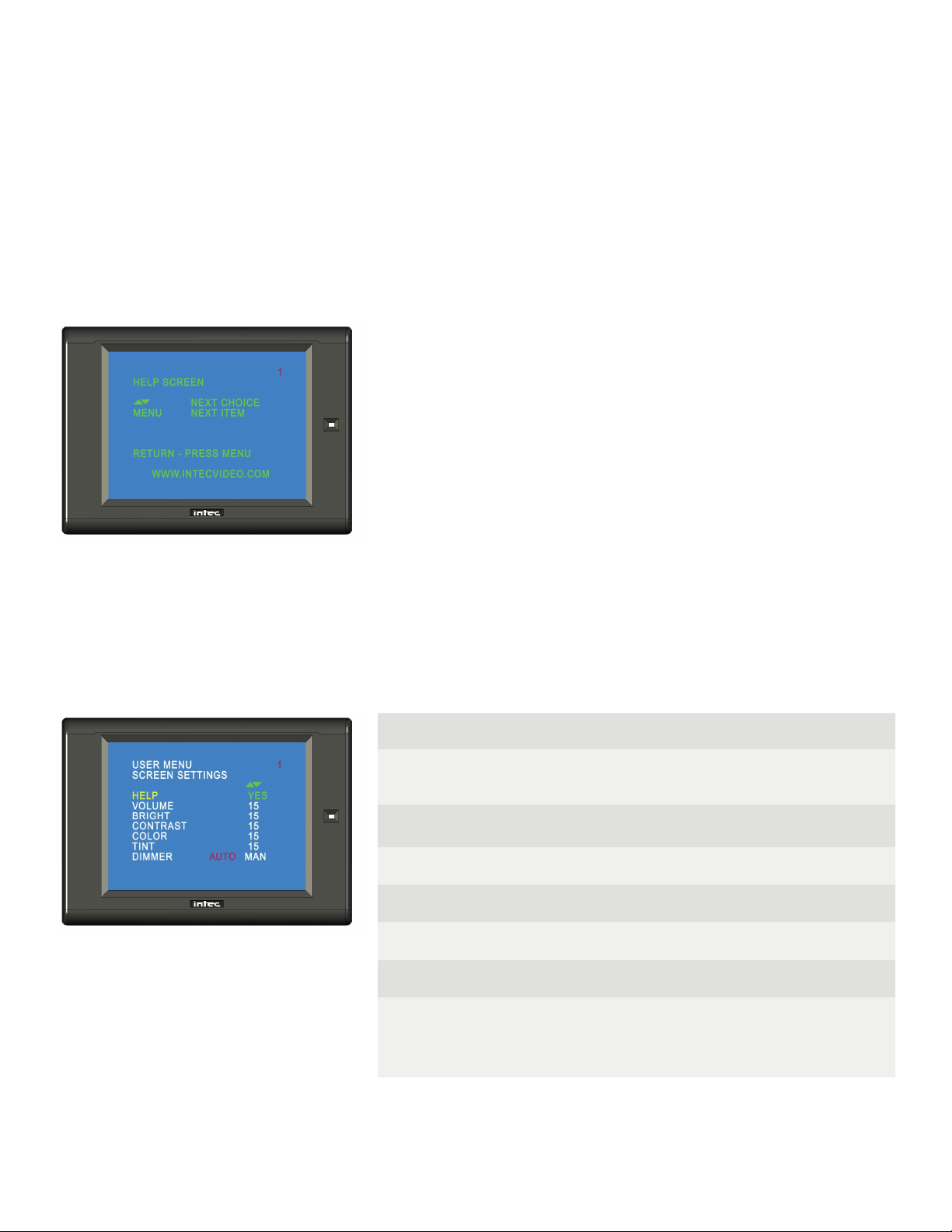
Help Screen
The Help Menu is accessed from the User Menu by pressing the up or down arrow button twice. Exit the Help Menu by
pressing any other button on the remote. There are no adjustments or settings available on the Help Menu.
User Menu
Press the Menu button on the CVR100 remote control to access the User Menu. Press the Menu button again to advance
to the next line item. Use the Up and Down arrow keys on the remote to change the value of the selected line item. The
Users Menu will time out after six seconds of inactivity.
Page 1 - Screen Settings
HELP Press the up or down arrow key twice to access the help
screen.
VOLUME Adjusts the volume level of the audio supplied by the
camera.
BRIGHT Adjusts the brightness of the image.
CONTRAST Adjusts screen contrast.
COLOR Adjusts color level.
TINT Adjusts screen tint.
DIMMER
When set to AUTO the screen will brighten or dim based
on the ambient light around it. When set to MAN the user
controls the screen brightness via the Up and Down Arrow
buttons on the remote.
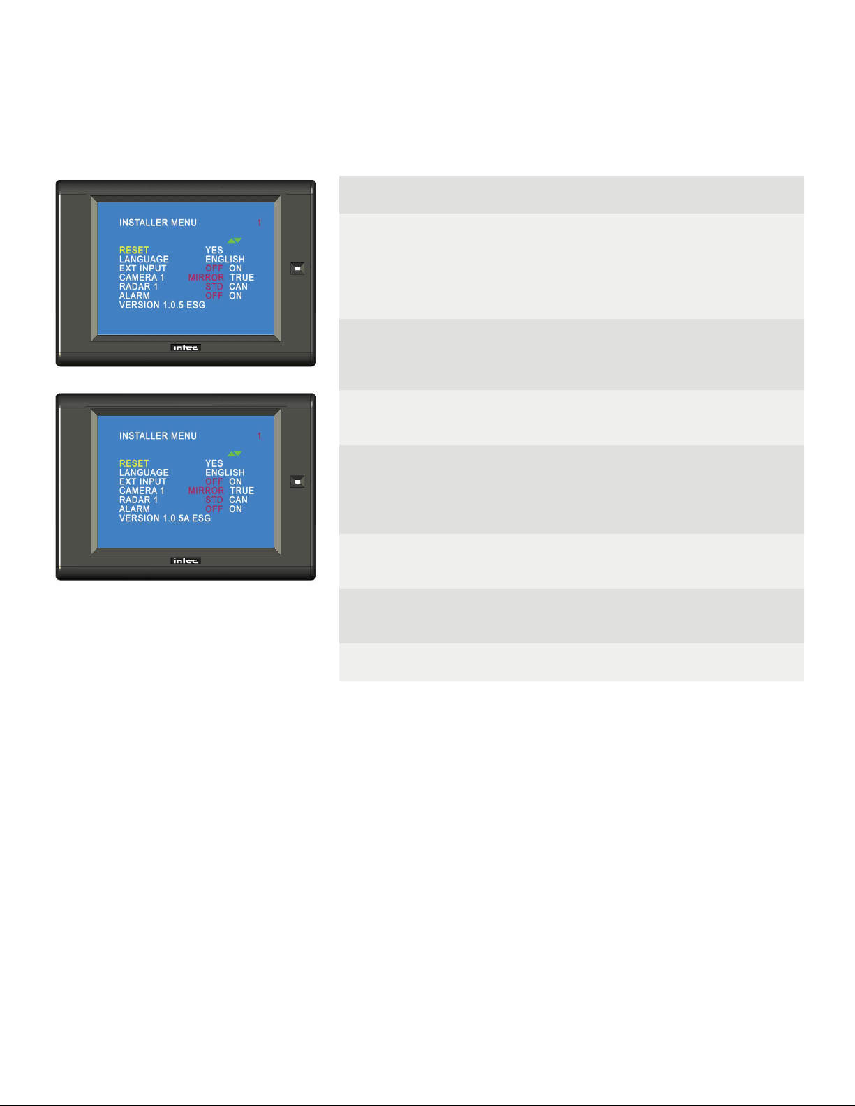
Installer Menu
Press the Menu and Up Arrow buttons simultaneously on the CVR100 remote control to access the Installer Menu. Press
the Menu button again to advance to the next line item. Use the Up and Down arrow keys on the remote to change the
value of the selected line item. The Installer Menu does not time out and must be exited manually. The simplest method is
via the ON/SB button on the remote.
Page 1
RESET
Resets the display back to the factory default. With
RESET highlighted press the up arrow button then press
MENU.
Note: Resetting the Installer’s Menu will also reset the
User’s Menu.
LANGUAGE
Highlight the desired language and press the Menu button
to set. Select from English, French, German or Spanish.
Not all Languages are available in all displays.
EXT INPUT
Turns on/off the External video input function. Note: For
dual camera applications using the CVS102 EXT IN must
be set to ON.
CAMERA 1
“MIRROR” Displays the image from an INTEC camera on
the screen as a Mirror image.
“TRUE” Displays the image from an INTEC camera on the
screen as a True image.
RADAR 1
Set to STD for standard radar, set to CAN for all others.
Note: Radar 1 connects to the camera input via an INTEC
cable and is only active when triggered.
ALARM
Turns the Radar Alarm Output function off and on. See the
Advanced Features section of this guide for more informa-
tion on radar.
VER Displays the current software version for your display.
Page 9

Advanced Features (CVS100 or CVS102)
External Video Input / Output (available in the CVS100 series controller)
Your system is equipped with an external video input that allows you to connect another video source. That source can
be from another camera, GPS, or any other composite video source. Note: The image orientation is native from the input
source and not reversible through display. In addition to the video input there is also a video and audio output. These al-
low you to output your native* Car Vision® camera video to an alternate display or DVR. The audio (when used with an
audio capable camera) can be output to an alternate speaker, display or DVR.
Use of the Video Input / Output requires the optional CVS100VO3M or CVS100MVO3M cable harness available from
INTEC.
* The output video is native from the camera meaning it sends video straight from the camera to the video output which in
most cases will produce a true image recording as opposed to the mirror image as seen on the display. To get a mirror
image recording you’ll need to reverse the camera image as well as set the image orientation in the display to TRUE.
Note: Not available in EXT.
Not all cameras are fi eld reversible and may need to be returned to INTEC to have the image reversed. Please contact
INTEC for additional information.
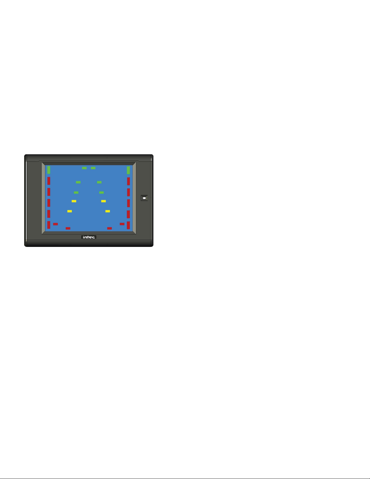
Integrated Active Object Detection (Radar)
The integrated radar, when properly connected, will send a visual alert to the Car Vision® display and an audible alert to
the Car Vision® remote when an object is detected within its operating range. The visual alert consists of OSD markers
on the left and right sides of the display screen. When properly connected and powered, green markers at the top of the
screen will illuminate indicating the radar is active. When an object is detected in the outer most detection area, the fi rst
of 5 red markers will illuminate starting at the top of the screen, directly below the green markers. As the object gets closer
to the radar sensor(s), or if the vehicle is moving and getting closer to the object, additional red markers will illuminate and
fl ash, and a beep increasing in frequency will be heard through the remote. While in reverse, the on-screen distance grid
will also fl ash according to the detected object’s distance from the sensor as shown below.
The integrated radar will operate only when connected via an INTEC cable to the Camera input on the controller. The
radar is activated via a +11 to +32 VDC source applied to the blue trigger wire of the controller’s power harness.
In addition there is a source voltage 1 amp radar alarm output (green) wire in the controller’s power harness that can be
used to activate an external device in the event your radar sensor detects an object within its range. ALARM must be set
to ON in the installer’s menu and the radar must be detecting an object within its range before the output voltage is
present. NOTE: Radar is only available with the CVS100 or 102M and CVS100 or 102XL controllers. It is NOT available in
the CVS100H or CVS102H.
Page 10

Page 11
Becoming Familiar with your CVR500 Remote
All adjustments to your Car Vision® system are made via the CVR500 remote control. For your convenience the buttons
on the remote are backlit to aid in use under low light conditions. The CVR500 remote also includes a speaker for audio
equipped systems and serves to provide an audible alert when the system is used in conjunction with our active radar
component.
Button Label and Function
Manually turns the display on or places it in standby.
Accesses the on-screen users menu.
Scrolls through the menu items.
Adjusts the radar audible alert volume between three available preset levels.
(Active when used with a compatible radar system)
Goes back to the prior character when naming camera positions.
Increases screen brightness.
Increases the value of a menu item.
Decreases screen brightness.
Decreases the value of a menu item.
Selects the external video input. (EXT must be set to ON in the Installer’s
Menu before EXT can be selected).
Displays the selected Multi-Camera View.
Skips to the next character when naming camera positions.
Manually Selects Camera 1
Selects the next page while displaying the menu
Manually Selects Camera 2
Selects the prior page while displaying the menu
Manually Selects Camera 3
Manually Selects Camera 4
Manually Selects Camera 5
Allows the user to Auto Cycle through the connected cameras.
Press both buttons simultaneously to access the Installer Menu.
One to Five Camera System Applications using a CVS500
Series Controller

Navigating the On Screen Display Menu (CVS500)
There are three menus available when using the CVS500 controller, the Help Menu, the User Menu and the Installer
Menu. The Help Menu explains the buttons used to navigate the menu. The User Menu allows you to adjust menu items
associated with the image such as brightness, contrast, etc... The installer Menu allows you to adjust the more
advanced features of your system such as image orientation, multi camera views, etc... Navigating the menu is done via
the CVR500 Remote Control.
Help Screen
The Help Menu is accessed from the User Menu by pressing the up or down arrow button twice. Exit the Help Menu by
pressing any other button on the remote. There are no adjustments or settings available in the Help Menu.
User Menu
Press the Menu button on the CVR500 remote control to access the User Menu. Press the Menu button again to advance
to the next line item. Press the CH1 or CH2 buttons to navigate to the next or prior page. Use the Up and Down arrow
keys on the remote to change the value of the selected line item. There are two User Menu pages.
Page 1 - Screen Settings
HELP Press the up or down arrow key twice to access the
help screen.
VOLUME Adjusts the volume level of the audio supplied by the
camera.
BRIGHT Adjusts the brightness of the image.
CONTRAST Adjusts screen contrast.
COLOR Adjusts color level.
TINT Adjusts screen tint.
DIMMER
When set to AUTO the screen will brighten or dim
based on the ambient light around it. When set to MAN
the user controls the screen brightness via the Up and
Down Arrow buttons on the remote.
Page 12

Page 2 - Cycle Settings
CAMERA 1
Thru
CAMERA 5
Adjusts the time (0 to 20 Seconds) the camera input will
be displayed when in the Cycle Mode.
Note: If all positions are set to “0” the cycle function will
be disabled.
EXT IN
Adjusts the time (0 to 20 Seconds) the EXT IN will be
displayed when in the Cycle Mode.
Note: EXT IN must be on before it can be included.
Installer Menu
Press the Menu and Up Arrow buttons simultaneously on the CVR500 remote control to access the Installer Menu.
Press the Menu button again to advance to the next line item. Press the CH1 or CH2 button to navigate to the next or
prior page. Use the Up and Down arrow buttons on the remote to change the value of the selected line item. There are
eight Installer Menu pages.
Page 1
RESET
Resets the display back to the factory default. With
RESET highlighted press the up arrow button then
press MENU.
Note: Resetting the Installer’s Menu will also reset the
User’s Menu.
LANGUAGE
Highlight the desired language and press the Menu
button to set. Select from English, French, German or
Spanish.
Note: Not all Languages are available in all displays.
EXT INPUT Turns on/off the External video input function.
DISTANCE
Turns the distance grid off or on.
Note: The distance grid is only active when camera 1 is
triggered via the camera 1 trigger wire.
VER Displays the current software version for your display.
Page 2 - Image Orientation
CAMERA 1
Thru
CAMERA 5
“MIRROR” Displays the image from an INTEC camera
on the screen as a Mirror image.
“TRUE” Displays the image from an INTEC camera on
the screen as a True image.
Note: CAMERA 1 thru CAMERA 5 are the default names assigned to
each of the fi ve camera inputs. You have the option of changing those
input names on Page 3 of the Installer Menu. Should you do so your
assignments will display throughout the menu.
Page 13

Page 4 - EXT Multi-View
MUL.DISP
Sets the multi screen view that will be displayed via the
EXT button on the remote control.
Press the up arrow button to turn the Multi-View display
off or press the down arrow button to change the multi-
screen view from QUAD to UP TRI, LOW TRI, or DUAL.
The default setting is Quad.
VIEW 1
Thru
VIEW 4
Used to select the Input displayed per screen segment.
Note: Changing MUL.DISP to a two or three camera
view will change the number of view options
accordingly.
See the Multi-Screen view section of this guide for more information.
Page 14
Page 5 - Trigger Multi-View
MTR.DISP
Sets the multi screen view that will be displayed via the
Orange trigger wire.
Press the up arrow or down arrow button to change the
multi-screen view from QUAD to UP TRI, LOW TRI, or
DUAL The default setting is DUAL
VIEW 1
VIEW 2
Used to select the Input displayed per screen segment.
Note: Changing MTR.DISP to a three or four
camera view will change the number of view options
accordingly.
See the Multi-Screen view section of this guide for more information.
Page 3 - Input Name
INPUT 1
Thru
INPUT 5
EXT IN
RADAR 1
RADAR 2
Sets the displayed name for the selected position. 0
thru 9, A thru Z and a number of special characters,
including a Space, are available. Names can be up to 8
characters in length.
Press or press and hold the Up or Down Arrow
buttons. Up increments the character up in order, Down
decreases the character. EXT selects the next charac-
ter position. The Radar Volume button selects the prior
character position. Assigned names display throughout
the menu.
Radar is NOT available in the CVS500H and the option will not be
displayed in the menu if that controller is used in the system.
Installer Menu Continued

Page 6 - Output Cycle (Active only when CYCLE is selected as one of
the Video Outputs)
INPUT 1
Thru
INPUT 5
EXT IN
Adjusts the time (0 to 20 Seconds) the camera input will
be displayed.
Note: If all positions are set to “0” the output cycle
function will be disabled.
OUTPUT
CYCLE
Used to set the video output cycle times. Highlight
SAVE and press the up arrow button. The word SAVE
will change to OK indicating the programmed times
have been saved.
Page 7 - Video Output
OUTPUT 1
Thru
OUTPUT6
Allows you to select which video options are available at
any one of the up to six video outputs.
Options available are: Camera positions 1 thru 5,
Multiple Display, Cycle and EXT IN.
The CVS500M allows for only 3 programmable video outputs. V.OUT.4
through V.OUT.6 will not be displayed in the menu.
Page 15
Page 8 - Audio Output and Radar Select
OUTPUT 1
OUTPUT 2
Allows you to set which camera audio is available at
either of the two audio outputs.
RADAR 1
RADAR 2
Set to STD for standard radar, set to CAN for all others.
Set to OFF to disable the radar function.
Note: Radar 1 is associated with camera 1 and is only
active when camera 1 is triggered.
Radar 2 is associated with camera 2 and when
connected will always be active except when camera 1
is triggered.
ALARM 1
ALARM 2 Turns the Radar Alarm Output function off and on.
Radar is NOT available in the CVS500H and the option will not be
displayed in the menu.
Installer Menu Continued

Advanced Features when used with a CVS500 Controller.
External Video Input
Your system is equipped with an external video input that allows you to connect another video source. That source can
be from another camera, GPS, or any other composite video source. Note: The image orientation is native from the input
source and not reversible through display.
Use of the Video Input requires the optional CVS500VO3M or CVS500MVO3M cable harness available from INTEC.
*Adding an INTEC CVC series camera to the External Video Input requires the VAP adapter. Contact your INTEC sales
representative for additional information.
Programmable Video / Audio Output
Up to 6 video outputs (3 video outputs for the CVS500M) and up to 2 audio outputs can be programmed to display any
single camera position, as well as, the multi-screen views and the external automatic cycle regardless of what is currently
being displayed on the screen.
The outputs will continue to provide video out to record whether the display is on or in standby. Use of the external video
and audio output feature is possible only when the controller is combined with an Intec CVD series display. Use of the
External Video / Audio output requires INTEC’s CVS500VO3M (for CVS500H and XL controllers) or CVS500MVO3M (for
CVS500M controllers) video I/O harness.
Refer to the On-Screen Installer Menu pages 7 and 8 or page 15 of this guide for information on setting up the
programmable audio and video outputs.
* The output video is native from the camera meaning it sends video straight from the camera to the video output which in
most cases will produce a true image recording as opposed to the mirror image as seen on the display. To get a mirror
image recording you’ll need to reverse the camera image as well as set the image orientation in the display to TRUE.
Note: Not available in EXT.
Not all cameras are fi eld reversible and may need to be returned to INTEC to have the image reversed. Please contact
INTEC for additional information.
Note: Programmable Audio and Video outputs are only available in the CVS500 Controller Version 2.0 or later and provide
native camera video, therefore the image recorded may display opposite of that shown on the Car Vision® display. Some
INTEC CVC Series cameras are equipped with an image reversal switch. See your cameras quick installation guide for
details or contact INTEC for additional information or assistance in setting up your particular application.
Naming Input and Radar Positions
Each input (camera) and radar position can be named as to its purpose. For example, the rear camera can be named
“REAR”. By naming the camera position, the operator will be able to quickly and clearly identify what camera view they
are looking at when they switch positions. Names can be up to 8 characters long and can include letters, numbers, special
characters and spaces. Refer to page 3 of the Installers menu or page 14 of this guide for instructions on setting up input
names.
Page 16
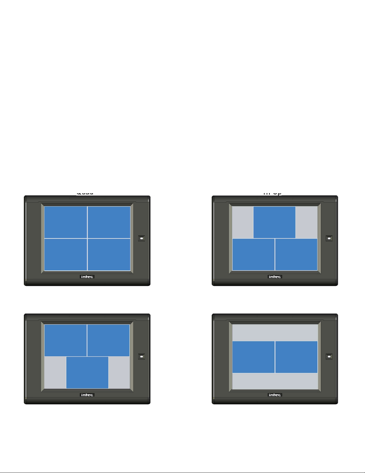
Multi Display Camera View
There are 4 multi display camera views available. They are; Quad, Tri Up, Tri Low, and Dual.
The multi display camera views are fully programmable through the on-screen menu and allow you to select which
camera position(s), 1 – 5, are displayed in each view. Setting a camera positions to “E” will eff ectively turn that position off .
Setting all camera positions to “E” will display a grey screen.
To select what view will be displayed via the <EXT> button please refer to page 4 of the installers menu or page 14 of this
guide.
Note: Only one multi display camera view can be programmed for the <EXT> button.
Triggered Multi Display Camera View
In addition to the EXT button multi display camera view there is a separate independently programmed triggered multi
camera view available. This additional view is set up through page 5 of the installers menu and in the same manner as
above. It is displayed when you apply +11 to +32 VDC to the orange trigger wire and can be connected to a switch to
allow for a second multi display camera view if needed in your application.
Refer to the following images for the multi camera and triggered multi camera views available.
Quad Tri-Up
Tri-Low Dual
Page 17

Programmable Auto Camera Cycle
The Auto Cycle allows the user to select dwell time intervals from 0 to 20 seconds for each camera position, including
external video in. They will be displayed on the screen for the preset period of time before cycling to the next camera
position. Setting the cycle time to “0” (zero) will exclude that position from being displayed during the cycle. Refer to page
2 of the On-Screen Menu or page 13 of this guide for information on setting up the programmable camera cycle.
Once set up the Auto Cycle can be accessed by either pressing the CYCLE button on the remote or when the cycle
trigger (light blue) wire is activated.
Note: If all camera positions are set to “0”, the cycle function is disabled.
Programmable Output Auto Camera Cycle
In addition to the Programmable Auto Camera Cycle there is a separate Programmable output Camera Cycle that allows
you to set an alternate cycle that can be recorded via one of the available video outputs. Setting up output cycle is done
through the installers menu, page 6. Refer to page 15 of this guide for more information.
Note: The output Auto Camera Cycle is only available when set via an available video output.
Page 18
Page 19
Integrated Active Object Detection (Radar)
The integrated radar, when properly connected, will send a visual alert to the Car Vision® display and an audible alert to
the Car Vision® remote when an object is detected within its operating range. The visual alert consists of OSD markers
on the left and right sides of the display screen. When properly connected and powered, green markers at the top of the
screen will illuminate indicating the radar is active. When an object is detected in the outer most detection area, the fi rst
of 5 red markers will illuminate starting at the top of the screen, directly below the green markers. As the object gets closer
to the radar sensor(s), or if the vehicle is moving and getting closer to the object, additional red markers will illuminate and
fl ash, and a beep increasing in frequency will be heard through the remote. While in reverse, the on-screen distance grid
will also fl ash according to the detected object’s distance from the sensor as shown below.
The integrated radar is available for camera positions 1 and 2, and will operate only when connected via an INTEC cable
to either of those positions on the controller. Radar 1 is activated via a +11 to +32 VDC source applied to the blue trig-
ger wire of the controller’s power harness. Radar 2 is active anytime there is power applied to the system and camera
1 is NOT triggered, even if the system is in Standby. Should an object be detected by radar 2 when the system is in
Standby(or if a camera other than 1 or 2 is selected?), the display will turn on and display the video from camera 2 as well
as provide the radar alert as described above..
In addition there is a source voltage 1 amp Radar Alarm output (green) wire in the controller’s power harness that can be
used to activate an external device in the event your radar sensor detects an object within it’s range. ALARM must be set
to ON in the installer’s menu and the radar must be detecting an object within its range before the output voltage is
present. NOTE: Radar is only available with the CVS500M and CVS500XL controllers. It is NOT available with the
CVS500H.

Page 20
Additional Features when used with a CVS500 Controller
Trigger Sequencing
Camera 1 through 5, Multi Display and Cycle triggers follow a priority sequence with camera 1 having the highest priority
followed by camera 2 and so on until the Cycle trigger, with the Cycle trigger having the lowest priority. The following chart
shows the priority sequencing.
Turn Signal Triggering
The CVS500 is equipped with pulse latch triggering on camera position 2 and 3. This pulse latch will allow the system to
remain triggered (on) even when attached to a power source such as a turn signal feed that pulses off and on.
Camera’s 2 and 3 will remain active for approximately 2.5 seconds after the voltage has been removed from the corre-
sponding trigger.
Momentary Rear Camera Override
While triggered, the rear camera can be momentarily overridden by pressing and holding down the CH 4 or CH 5 buttons
on the remote. While holding down the button, the camera image will change to the corresponding camera position and
will return to the rear camera when the button is released. The momentary override can only be done with camera
positions 4 and 5 and will only override camera position 1 while it is triggered.
Trigger Priority
Wire Color Function Priority
Blue Camera 1 Trigger 1st
Yellow Camera 2 Trigger 2nd
White Camera 3 Trigger 3rd
Green Camera 4 Trigger 4th
Brown Camera 5 Trigger 5th
Orange Multi Display Trigger 6th
Light Blue Cycle Trigger 7th
This manual suits for next models
1
Table of contents
Other Intec Car Video System manuals


