intech 21 HWHC2100 User manual

HWHC-2100 Operation Manual CONFIDENTIAL
21 Harbor Park Dr. N, Port Washington, NY 11050 Phone: 516.626.72211 Fax: 516.626.7201
1
Hot Water Heating Controller
Hot Water Heating Controller HWHC2100
Operation Manual
1. Introduction
The Hot Water Heating Controller HWHC2100 (Fig 1) provides control of the Building's mixing valve, heat
exchange valve or the burner operations to regulate the heating water temperature or the amount of thermal energy
supplied to the Building. The HWHC2100 adjusts the temperature of the heating water, calculating the target
temperature, in response to changes to the outdoor temperature. The HWHC2100 controls the motorized valve and the
circulation pumps. Alternatively, the control could be provided directly to the burner operations.
In Auto mode the HWHC2100 distributes heat energy entering in the building in accordance with weather,
outdoor temperature and installed parameters. Depending on the controller’s configuration the main parameter of the
regulation could be either the hot water in house input the supply temperature (system water temperature) or condensate
return temperature (return water temperature).
HWHC2100 works as a standalone controller and can be connected to a Local Server, which provides additional
parameters adjustments to HWHC2100 based on apartment's indoor real time temperature. This feature will improve the
heating supply and distribution efficiency and can eliminate the apartments over or under heating. When the HWHC2100
is connected to the Local Server it can be monitored and controlled from the local Intranet and/or Internet with
appropriate authentication.
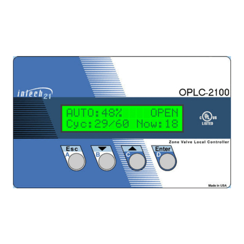
Fig1. HWHC2100. Front view
The HWHC2100 features:
•Configurable to controls the zone valve or boilers to regulate the circulated water temperature.
•Adaptable to different type of actuators: floating point, 4-20mA, 0–5V, 0–10V or 135ohm input.
•Automatic positioning of the zone valve or adjusting the boilers stages in accordance with operation settings and
measured temperatures.
•Manual Control Mode.
•Displays the valve position circulation pumps and/or boilers status.
•Day and Night modes of operation with programmable time durations.
•Programmable heating season dates.
•Flexible selection of the feedback control temperature source (system (supply) or return).
•Extended Heat-Up period up to 100 minutes with step of 1 min.
HWHC2100

HWHC-2100 Operation Manual CONFIDENTIAL
21 Harbor Park Dr. N, Port Washington, NY 11050 Phone: 516.626.72211 Fax: 516.626.7201
2
•Morning Boost period up to 120 min or Vari-Boost (the length of the Boost time depends on the Outdoor
temperature).
•Adjustable Indoor Temperature Cutoff (Day/Night) Set-Point. Based on the average apartment’s temperature
(Average Indoor Temperature) supplied from the host.
•Adjustable Return Temp or System (Supply) Temperature Cutoff Set-Points.
•Adjustable Zone of no action (D_Band) near the any Cutoff Set-Point.
•Adjustable Cut-Off depth from 0-100%.
•Displays outdoor and hot water heating system supply and return temperature.
•Detects for open and short of the temperature sensors input and displays on the status screen.
•Adaptable to different types of standard temperature sensors and valve motors.
•Provides compensator control for unusual weather conditions.
•Programmable maximum and minimum system (or return) water temperature.
•Internal real-time clock/calendar with backup battery.
•Automatic Daylight Saving Time clock adjustment.
•Automatic circulation pumps ON/OFF control with an adjustable outdoor cut-off.
•Automatic storage of setup values. No loss of setup values or mode of operation if power is OFF for extended time.
•Initial valve synchronization on power up.
•Automatic valve synchronization while in operation to eliminate possible deviation of the actual and calculated
valve positions.
•Simple calibrations procedures.
•Locally controlled by the four-button keypad and convenient menu.
•Password protection for the critical parameters settings.
•Remotely controlled and/or monitored through the RS485 interface.
2. Control
The four-button keypad and 16 characters by 2 lines LCD backlit display are located on the front panel of the
HWHC2100. These controls provide full local management of the system. Operator can read system setting and parameters
(e.g. temperatures, valve position and alerts), set the operational modes, or change settings.
The control keypad consists of four pushbuttons: Escape (Esc), Down (), Up (), Enter (Enter). The keys are
also marked with letters A, B, C, D used to simplify the passwords memorizing.
During normal operation the upper line of the display shows a current operation mode: OFF, AUTO, MANUAL OPEN
(M_OPEN), MANUAL CLOSE (M_CLOSE), MANUAL SET (M_SET), target temperature (on AUTO or M_SET mode of
operation), and system’s status information (please see page ). When calibration modes selected, the upper line displays the
information regarding particular mode.
The line at the bottom of the display is dedicated to various status information and menu-driven setup dialogs. To
browse to more options press the Enter key at the “Enter for more …” status information line.
3. Operation
The HWHC2100 checks the Outdoor temperature (OD) by means of an Outdoor Sensor, at the same time it
monitors the hot water system temperature (ST) or hot water return temperature (RtnT) of the building’s heating system by
means of the ST or RtnT Sensor. Controlled temperature (ST or RtnT) is main parameter of regulation. It could be selected
from the menu by properly setting of the controller’s configuration for a particular application.
In the AUTO mode when Outdoor temperature falls below an adjustable Outdoor cutoff temperature, the controller activates
the system pump and provides automatic positioning of the control valve in accordance with the configuration, measured
temperatures, season, time of day, and selected parameters. If the ST(or RtnT) is different from the controller calculated
Target Temperature, the HWHC2100 will correct the difference by moving the valve toward the close or open position.
Also the controller can monitor return water temperature or system water temperature. This feature is activated from the
controller’s configuration and by setting water (System or Return) Temperature Cut Off Set Point (please refer to the
controller’s Menu on fig.2 or description on page 10). If ST(or RtnT) above the Cut Off Set Point the Valve shell be close.
In the MANUAL SET mode the controller automatically keeps the System Hot Water Temperature or the Return Water

HWHC-2100 Operation Manual CONFIDENTIAL
21 Harbor Park Dr. N, Port Washington, NY 11050 Phone: 516.626.72211 Fax: 516.626.7201
3
Temperature at the set-point entered by operator. In this case the HWHC2100 dose not uses the Outdoor temperature sensor.
There are three additional operation implemented in the controller, they are useful when performing motor/valve
maintenance, calibration or in emergency situation. Detailed description of the operation modes can be found on section 5.
The controller has a possibility of management motorized valves with three different types of interface:
1. General Purpose Relays;
2. Current Loop (4ma -20ma);
3. Potentiometer.
In two last cases additional board is required on the controller.
Selection the type of the motorized valve can be made from SETUP menu (please refer to the controller’s Menu on fig.2 or
description on page 10).
On power-up the HWHC2100 restores all setup values. This eliminates the need for manual configuration re-entry.
The last active operation before power down is also recovered.
Attention!!! Following description only for the motorized valve controlled by external relays!!!
Upon power-up the controller enters to Initial Synchronization state to synchronize the valve to the close position. During
this time the LCD display indicates: the mode of operations and the current operational state - upper line, elapsed time (in
seconds) to finish synchronization and system temperature - bottom line.
M_CLOSE: Sync_C
137sec ST = 145°
The elapsed time interval for the valve adjustment depends on the type of the motor used.
The valve will be fully opened or closed depending on the mode of the last operation as follows:
Operation Mode
Valve Direction
Status Information
AUTO
To Close Position
Sync_C
M_SET
To Close Position
Sync_C
M_CLOSE
To Close Position
Sync_C
M_OPEN
To Open Position
Sync_O
OFF
To Close Position
Sync_C
During the Initial Synchronization, the operator has full access to the controller. He can check temperature (OD ,ST, and
RtnT), calibrate sensors, change setup parameters, change mode of operation, etc.
Please note the following:
1. All operation mode changes will be displayed on the LCD. But only last change will be executed when the Initial
Synchronization completes.
2. If during the Initial Synchronization, the operator does not change the mode of the operation and restored operation
was OFF, the controller will put the valve in the position prior to power down.
If during the Initial Synchronization, the operator change previous operation mode to OFF mode, then the valve
will remain on the same position when the Initial Synchronization complete.
4. Menu
The process of interaction is menu driven. Menu chart is shown on Fig 2. The menu is organized in convenient and
logical way, and follows a simple set of rules.
•The menu chart is organized as a set of menu boxes. To navigate between the boxes one should press
Enter key to move to the right on the chart, and Esc key to move backward.
•Each box contains one or more menu items. To switch between the items inside a box one should press Up
or Down keys.
•Each item represents one menu entry - select a parameter to change, enter a new parameter value, change
mode of operation etc.
If the item contains "NEW" word then the new value has to be entered, and Up and Down keys will
change the value, pushing Enter accepts the new value, Esc - rejects the new value, and leaves the

HWHC-2100 Operation Manual CONFIDENTIAL
21 Harbor Park Dr. N, Port Washington, NY 11050 Phone: 516.626.72211 Fax: 516.626.7201
4
parameter unchanged.
•If a password is required then one should enter a certain key sequence. For convenience the passwords are
coded as the sequence of letters (e.g. DDBBCBA).
•Starting point of the menu is the topmost item of the leftmost box (current valve position VLV =xx%) on
the chart. If lost in the menu just press Esc repeatedly, until the display shows VLV =xx%. You are now in
the upper left corner of the menu chart.

HWHC-2100 Operation Manual CONFIDENTIAL
21 Harbor Park Dr. N, Port Washington, NY 11050 Phone: 516.626.72211 Fax: 516.626.7201
5
Fig.2 HWHC2100 Menu (V2.48) - Lower line of the display
VLV=16% ST=148°
(VLV=16% RT=108°)
SET OPER MODE
NEW Mode=AUTO
Rtn Temp=97.4°F
(Sys Temp =145°)
NEW Mode=M_OPEN
OD Temp = 17.6°
NEW Mode=M_CLOSE
PUMP ON
NEW Mode=M_SET
NEW MTGTemp=160°
VLV=15.8%
NEW Mode=OFF
10:25am Nov10'05
CACADCB
Enter for more…
SETConfiguratin
Password1:******
ST-TGT RtnT-NA
RtnT-TGT ST-NA
ST-TGT RtnT-Ctf
RtnT-TGT ST-Ctf
HWHC2100/644
CACADCB
VERSION V2.48
SETUP
Password1:******
SET D_Band
NEW D_Band =1.2°
ST-TGT RtnT-NA
SET RtnCutOffTem
NEW RCutOffTm=70°
OD Temp = 17.6°F
SET SysCutOffTem
NEW SCutOffTm=70°
Sys Temp=168.8°F
SET MaxWaterTemp
NEW MaxWTmp=242°
Ret Temp=45.8°F
SET MinWaterTemp
NEW MinWTmp=80°
RtnCutOffTm=70°F
SET PumpRunDelay
NEW PumpRunD=2m
SysCutOffTm=70°F
SET HeatUp Time
NEW HeatUpTm=30m
cTGT Temp:196.4°
SET Motor Pause
NEW MrPause=20s
D_Band = 1.2°
SET VlvCtrl Type
NEW CtrlTp=Curnt
Motor Type = 2m
SET Motor Type
NEW MotorType=2m
Motor Pause=20s
SET TIME & DATE
SET Minute
NEWMinute=56
VlvCtlType=Curnt
SET Com.ID
NEW Com.ID=3
SET Hour
NEW Hour=2PM
D:Mild = 55°F
CACADCB
SET Month
NEW Month=02
N:Mild = 45°F
SET MAINTENANCE
Password1:******
SET D:Mild
NEW D:Mild=75°
SET Date
NEW Date=5
N:Stbk = 10°F
SET N:Mild
NEW N:Mild=25°
SET Year
NEW Year=9
MaxWaterTmp=242°F
SET N:Stbk
NEW N:Stbk=20°
MinWaterTmp=180°F
SET Heat Gain
NEW HG=1:1.25
PumpRunDelay=2m
SET Compensator
NEW Compens=0°
Heat Gain=1:1.25
SET Boost Span
NEW BoostSpn=90m
Compensator=0°F
SET BoostAdvance
NEW Boost Adv=12°
Boost Span=90m
SET In D:CutOff
NEW D:CutOff=70°
BoostAdvance=12°
SET In N:CutOff
NEW N:CutOff=70°
D:ICutOff = 70°F
SET InDoorDBand
NEW InDBand=4.5°
N:ICutOff = 60°F
SET Day Begin
NEW Begin=5:00am
InDrD_Band=2.5°F
SET Day End
NEW End=10:00pm
InDoorTem=N/A
SET Winter Begin
NEW Begin=Oct15
Day Begin=5:00am
SET Winter End
NEW End=May 15
Day End=10:00pm
DDBBCBA
WintrBegin=Oct15
SET CALIBRATE
Password2:******
CAL OUT Temp
NewODTAdj=0.2°
WinterEnd=May 15
CAL SYS Temp
NewSysTAdj=0.1°
HeatUp Time=30m
CAL Rtn Temp
NewRtnTAdj=0.0°
Com.ID = 1
CAL ValveClosePs
NEW VlPsAdj
HINT: If lost in the menu or a password is unknown - push ESC repeatedly, until the display shows VLV =xx%. You are now in the upper left corner of the menu table

HWHC2100 v2.53 Operation Manual CONFIDENTIAL
21 Harbor Park Dr. N, Port Washington, NY 11050 Phone: 516.626.72211 Fax: 516.626.7201
6
5. Configuration of the controller.
Depending on specific particularity of the consumption of the heat energy and accepted schemes of the heating,
the controller can be set to four different configurations as follows:
Hot Water System Temperature and Return Water Temperature are
used as:
Indication on the
LCD:
SysTmp - Target, ReturnTmp - CutOff
ST-TGT RtnT-Ctf
SysTmp - Target, ReturnTmp - Not use
ST-TGT RtnT-NA
SysTmp –Ctf, ReturnTmp –Target
ST-Ctf RtnT-TGT
SysTmp –Not use, ReturnTmp–Target
ST-NA RtnT-TGT
To switch between the different configuration one should press Up or Down keys. Hitting Enter key accepts the new
configuration, Esc - rejects and leaves the configuration unchanged.
6. Modes of operation
The upper line of the display shows the current mode of operation (OFF, AUTO, M_SET, M_OPEN, M_CLOSE),
indicates System Target Temperature during AUTO or M_SET operation. The right corner of the upper line indicates
operational state. (Please refer to the detailed description on section 7).
The HWHC2100 operates in one of the following modes:
Operation
Mode
Description
OFF:
The valve stops immediately in the position it has before operation was entered, pump relay de-
energized.
The controller is hot ready, continuing measurements and processing the sensors' data. This mode
is useful when performing motor/valve maintenance and in emergency situation.

HWHC2100 v2.53 Operation Manual CONFIDENTIAL
21 Harbor Park Dr. N, Port Washington, NY 11050 Phone: 516.626.72211 Fax: 516.626.7201
7
AUTO:
The controller provides automatic valve positioning in accordance with the measured temperatures,
season, time of the day, and the selected parameters. This mode is designed to be the main mode of
operation. If the system parameters are set properly, then there is no need in manual intervention in
the system performance virtually at any weather condition. The HWHC2100 is capable to keep
calculated target temperature in parameters set by ‘D_Band’ set point.
In AUTO mode the controller distinguishes four day periods (Fig.6):
1. The morning heat-up period starts at the‘DAY BEGIN’ Set Point. During this period the
controller changes the valve position from nighttime to daytime temperature values with a
constant rate. The heat-up time span is variable form 0 to 100 minutes (with step of 1 minute).
2. The morning boost period begins immediately after the morning heat-up period ends. The
‘BOOST SPAN’ and ‘BOOST ADVANCE’ parameters define the boost duration and its
amount.
3. Normal daytime operation begins from the Boost period end to ‘DAY END’ Set Point.
4. Nighttime period (‘DAY END’to ‘DAY BEGIN’). The amount of delivered heat can be
reduced against the daytime period, as defined by the’ NIGHT MILD WEATHER’ and
‘NIGHT SETBACK’ parameters. (Please see an example in section 6).
Notes:
The valve will be unconditionally set to 0% when:
- Out Door Temperature achieves Day time Mild Weather Set Point (at Day Time) or Night
Mild Weather Set Point (at Night time);
- Apartments temperature (Indoor Temperature) average supplied from host computer highest
then Indoor Temperature CutOff (Day/Night)set Point plus D_Band.
- If Return Water Temperature(or System Water Temperature) above the Cut Off Set Point
- If current date is between the Winter End and Winter Begin settings (Summer time).
M_SET:
(Manually Set
Temperature)
In this mode the HWHC2100 automatically keeps the Supply (System) Hot Water Temperature (or
Return Water Temperature) at the set point entered by operator within a dead band zone set by
‘D_Band’ parameter. (In case the outdoor sensor failed in AUTO mode, the HWHC2100
automatically switches to this mode of operation).
M_OPEN:
(Manually Open)
M_CLOSE:
(Manually
Close)
These modes can be used in emergency to open or close the valve fast and completely regardless of
the valve position.
The M_OPEN unconditional opening of the valve and turning pump on (if it was off).
The M_CLOSE unconditional closing of the valve. After valve close the pump will stay on for a
period of 2 seconds and will turn off.
To change the mode, select SET OPER MODE item in the menu, press Enter, then, with Up or Down key select a
new mode, and press Enter. When the M_SET mode is selected, the new temperature value (‘MTGTemp’) must be
entered.

HWHC2100 v2.53 Operation Manual CONFIDENTIAL
21 Harbor Park Dr. N, Port Washington, NY 11050 Phone: 516.626.72211 Fax: 516.626.7201
8
7. Operation Parameters
To provide correct and reliable operation of the HWHC2100 the operational parameters must be set properly.
The parameter section of the menu is divided in two parts (MAINTENANCE and SETUP). Each part protected with a
password. Use following tables as guidelines when selecting parameters' values:
MAINTENANCE (password:CACADCB)
Parameter
Description
Heat Gain
Determines ratio between the System Hot Water Temperature and Outdoor Temperature.
Fig. 3a,b represents the family of control curves with different Heat Gain as parameter when Mild Weather is
70°F (Fig.3a) and Mild Weather is 55°F (Fig.3b). With any of the ratios, the colder it becomes outside, the hotter
the temperature of the system water. On the both examples Compensator=0 and NIGHT SETBACK=0.
Positive Compensator values shift the curve up, negative - down.
Positive Night Setback values shift the curve down.
Positive Compensator values shift the curve up, negative - down.
Positive Night Setback values shift the curve down.
Implemented 10 different ratios: 1:3; 1:2; 1:1.5; 1:1.25; 1:1; 1.25:1; 1.5:1; 2:1; 3:1; 4:1.
Ratio 4:1 (OD : ST) - the outdoor temperature would have to drop 4° to increase the system water temperature
by 1 degree.
Ratio 1:3 (OD : ST) - for each 1 degree drop in outdoor temperature the hot water temperature will increase by
3 degree.
Default ratio is 1:1;
Fig.3a Heat Gain
Ratio (Mild
Weather is 70°F )
curves.
70
100
130
160
190
220
250
-20 -10 0 10 20 30 40 50 60 70
Outdoor Temperature (in F)
System Water Temperature (in F)
1:3
1:2
1:1.5
1:1.25
1:1
1.25:1
1.5:1
2:1
3:1
4:1

HWHC2100 v2.53 Operation Manual CONFIDENTIAL
21 Harbor Park Dr. N, Port Washington, NY 11050 Phone: 516.626.72211 Fax: 516.626.7201
9
Fig.3b Heat Gain
Ratio (Mild
Weather is 55°F )
curves.
70
100
130
160
190
220
250
-20 -10 0 10 20 30 40 50
Outdoor Temperature (in F)
System Water Temperature (in F)
1:3
1:2
1:1.5
1:1.25
1:1
1.25:1
1.5:1
2:1
3:1
4:1
Compensator
The Compensator parameter provides day(or night) adjustment to the amount of heat being delivered to compensate
for the influence of extreme weather condition. When calculating target temperature, the controller, adds or subtracts
the Compensator value from the calculated temperature. Therefore, any change made to the Compensator will
change the value of the calculated target temperature by the same amount and will change position of the valve.
Positive values of the parameter increase heat delivery (more opens valve), while negative values reduce it (closes
the valve). Fig.4 illustrates effects of the Compensator on the control curve.
Range: -40°F to +40°F with 1° step. Default value is 0°F.
D:Mild
(DAY MILD
WEATHER)
The controller closes the valve completely when the outdoor temperature is higher than this parameter and the
time between 5AM and 10PM. The Pump will work on for a period of time set by the ‘PumpRunDelay’ setpoint
and will turn off.
Range: 40° to 80 °F with 1° step. Default value is 55°F.
N:Mild
(NIGHT
MILD
WEATHER)
If the outdoor temperature is higher than this parameter and the time is between 10PM and 5AM, then the valve
is closed completely. The Pump will work on for a period of time set by the ‘PumpRunDelay’ setpoint and will
turn off.
If the outdoor temperature is lower than this parameter and the time is between 10PM and 5AM, then the valve
position is corrected in accordance with the ‘NIGHT SETBACK’ parameter.
Range: 20° to 60 °F with 1° step. Default value is 40°F.
N:Stbk
(NIGHT
SETBACK)
The controller subtracts from the previously calculated target temperature the ‘NIGHT SETBACK’ value to
reduce heat delivery during the nighttime.
Range: 0° to 80 °F with 1° step. Default value is 10°F.

HWHC2100 v2.53 Operation Manual CONFIDENTIAL
21 Harbor Park Dr. N, Port Washington, NY 11050 Phone: 516.626.72211 Fax: 516.626.7201
10
Fig.4 Reset
Ratio curve
‘1:1’ with
different
Compensator
parameters.
(Mild Weather
is 55°F)
Valve Close
100
140
180
-20 -15 -10 -5 0 5 10 15 20 25 30 35 40 45 50 55
Outdoor Temperature (in F)
System Water Target Temperature (in F)
Compens=+10
Compens=0
Compens=-10
Boost Span
Morning boost time span. The controller boosts heat only with AUTO mode in effect.
Range: 0, 30, 60, 90, 120 minutes (0 means no boost) or “Vari-Boost” (the length of the Boost time depends on
the outdoor temperature - Fig.4).
Fig.5 “Vari
Boost” curve
0
20
40
60
80
100
120
-20 -10 0 10 20 30 40 50 60
Outdoor Temperature (in F)
Time (minutes)
BoostAdvance
The controller adds the ‘BOOST ADVANCE’ value to the previously calculated system target temperature thus
increase heat delivery during the morning boost period.
Range: 0°to 30° F with 1° step (0 means no boost). Default value is 0.

HWHC2100 v2.53 Operation Manual CONFIDENTIAL
21 Harbor Park Dr. N, Port Washington, NY 11050 Phone: 516.626.72211 Fax: 516.626.7201
11
Fig.6 24 hours
round the clock
Heating Cycle
with Morning
Boost (Step of
the greed lines is
30 minutes).
Boost
142
144
146
148
150
152
154
156
158
160
162
164
0 5 10 15 20
Time (hours)
System Target Temperature (in
F)
Black line –Night Time Period (10:00PM –5:00AM); Green line –Morning Heat-Up (5:00AM –5:30AM);
Blue line –Day Time Period (5:30AM –10:00 PM); Red curve –possible Morning Boost (5:30AM –7:00AM).
In D:CutOff
(In Door Day
Temperature
Cutoff)
The controller closes the valve completely when the In Door temperature average (supplied from host computer)
is higher than this set point during the Day - time between Day Begin and Day End. (D:ICOFF state).
Range: 40 to 90 °F
In N:CutOff
(In Door Night
Temperature
Cutoff)
If the In Door temperature average (supplied from host computer) is higher than this set point and the time is
between Day End and Day Begin, then the valve will be closed completely. (N:ICOFF state).
Range: 40 to 80 °F
InDrD_Band
Used along with ‘In Door Temperature’ parameter and ‘In Door Day(Night) Temperature Cutoff’ Set Point. This
parameter defines the allowable delta between the actual In Door Temperature and Cutoff Set Point.
Range: 0.1°F to 19.9°F with 0.1°F steps.
DAY BEGIN
Hours and minutes (with 10 minutes step) when Day Begins
DAY END
Hours and minutes (with 10 minutes step) when Day Ends
WINTER
BEGIN
Month and Day when Winter Begin (dependent of the region)
WINTER
END
Month and Day when Winter End (dependent of the region)
SETUP (password:CACADCB)
Parameter
D_Band
Used in AUTO or M_SET modes. This parameter defines the allowable delta between the actual
System Water Temperature or Return Water Temperature (dependent of the Configuration) and
the Target Temperature. Range: 0.5°F to 25.5°F with 0.1°F steps.
RtnCutOffTem
Return Water Temperature Cut Off Set Point. If Return Water Temperature above the Cut Off Set

HWHC2100 v2.53 Operation Manual CONFIDENTIAL
21 Harbor Park Dr. N, Port Washington, NY 11050 Phone: 516.626.72211 Fax: 516.626.7201
12
Point the Valve shell be close. Range: 40°F to 220°F with 1°F steps. Default value is 70°F.
SysCutOffTem
System Water Temperature Cut Off Set Point. If System Water Temperature above the Cut Off Set
Point the Valve shell be close. Range: 40°F to 220°F with 1°F steps. Default value is 90°F.
MaxWaterTemp
Maximum allowed water temperature. If calculated Target temperature exceeds
MaxWaterTemp the controller in AUTO mode will maintain the water temperature at
MaxWaterTemp.
Range: 170°F to 250°F with 1° step. Default value is 250°F.
MinWaterTemp
Defines minimum water temperature in the system. Used only in the AUTO mode of operation.
The controller calculates the Target water temperature based on the outdoor temperature, heat gain,
and the compensator value and controls burner or valve to hold either the calculated temperature,
or the MinWater Temperature, whichever is higher.
Range: 70°F to 170°F with 1° step. Default value is 140°F.
PumpRunDelay
Sets the time to run the System Pump for a longer period of time after the boiler has been turned
off or the valve has been closed. This feature allows for dissipating the excess heat from the boiler
combustion chamber and prevent the boiler from overheating.
Range: 0 to 99 minutes with 1-minute step. Default value is 2m.
HeatUp Time
The heat-up time is designated to return the building temperature to its Day heat level after Night
heat level. Range: 0 to 99 minutes with 1-minute step. Default value is 30minutes.
Motor Pause
In AUTO and SET mode of operation specify the appropriate time (in seconds) between the Valve
(Motor) motion. Normally, this parameter is set at the system installation time.
Range: 0 to 127 seconds with 1 second step. Default value 30sec.
VlvCtrl Type
Defines Type of Control Interface to the motorized Valve.
There are three possible Type of Control Interface to the motorized Valve
implemented on the controller:
-Relays;
-Current Loop (4ma-20ma);
-Potentiometer.
oDefault Interface = Relay.
Motor Type
There are 8 types of motors (dependent on the time duration of valve close position to the open
position) from 2minutes to 9 minutes with increment of one minute. Type 2m –for time duration
of 2 minutes; Type 3m –for time duration of 3 minutes, and so on. Default value is 3m.
TIME & DATE
Current Year, Month, Day, and Time can be entered and adjusted. The "am/pm" displayed with
capital letters when Daylight Saving Time is in effect.
Com.ID
Each HWHC2100 connected to the local server via the RS485 bus. To establish proper connection
the controller should have a unique communication address (ID).
Range: 1 to 99.
8. System Status Information
All operational parameters and useful information can be seen on the low line of the LCD display by using Up/Down
and Enter keys (see Fig.2 left corner). The following information can be selected for displaying on the lower line of the
LCD:
Information
Example
Description
Valve Position and
System Temperature
(or Return Temperature)
VLV =16% ST = 152°
or
VLV =24% RT = 175°
Current valve position as percent of the Open status and
Hot water heating system temperature at the RTD sensor
(="fail" if temperature sensor malfunction).
Return Temperature
(or System Temperature)
Ret Temp = 60.4°
or
Sys Temp = 123.5°
Condensate return temperature at the RTD sensor.
If sensor not installed or not use: (“RtnTempSr-NotUse”),
If the sensor malfunction: (="fail")

HWHC2100 v2.53 Operation Manual CONFIDENTIAL
21 Harbor Park Dr. N, Port Washington, NY 11050 Phone: 516.626.72211 Fax: 516.626.7201
13
Outdoor Temperature
OD Temp = -12.3°
Outdoor temperature at the OD sensor (="fail" if
temperature sensor malfunction).
Configuration
ST-TGT RtnT-Ctf
SysTmp - Target, ReturnTmp - CutOff
Pump Status
PUMP ON *
The asterisk (*) is indicating the Winter season.
Exact Valve Position
VLV=15.8%
Useful to make sure that the system works properly
Time and Date
10:25am Mar10'09
Time, Month, and Year.
More information
Enter for more…
Pressing the ‘Enter’ key will show additional information
The following are examples of various controller operations as indicated on the LCD. The first line shows the mode of
operation, target system temperature and operational status. The second line shows additional information (see above
table). The short explanation of the LCD’s lines follows. The current status of the device dependent on many
parameters (modes of the operation, temperature, season, settings etc) and is located on the right corner of the upper line
of the LCD display.
Mode of Operation: AUTO
•For the motorized valve controlled by relays only
AUTO:176° D:Norm
AUTO:172° N:Norm
AUTO:188° HeatUp
VLV=37% ST=144°
VLV=37% ST=144°
VLV=37% ST=144°
Normal Day of Operation.
Calculated Target
Temperature is 176°F.
Normal Night of Operation.
Valve position is 37%(open).
System temperature is 144°F.
Morning Heat Up.
Calculated Target
Temperature is 188°F.
AUTO:189° BOOST
AUTO:140° D:Mild
AUTO:140° N:Mild
VLV=37% ST=155°
VLV=12% ST=144°
VLV_0% ST=144°
Morning Boost.
Calculated Target
Temperature is 189°F.
Day Mild Weather –Valve is
going to be close. The
automotive adjustment valve
position would execute.
Night Mild Weather –Valve
is close. The automotive
adjustment valve position is
executing.
AUTO:176° FailSf
VLV=17% ST=fail
System Temperature Sensor
fails. The valve would
transition into the close
position. After it, motor will run
certain amount of time to make
sure that the valve at the close
position (this procedure calls -
automotive adjustment valve
position). The motor would
stop, and after a short period of
time the valve would transition
into open position at 60%. The
motor would stop and the valve
would remain on this position
until the issue is resolved.
AUTO:140° FailSf
VLV=43% ST=132°
Outdoor Temperature Sensor
fails. The controller would use
external Outdoor Temp. info
from host or server, if they are
attached. If they are not
attached the controller would
use 35°F as Outdoor
Temperature night setpoin or
45°F as Outdoor Temperature
day setpoin.
AUTO:146° Sync_C•
168sec ST=80°
Initial Synchronization.
Valve is going to be close.
Calculated Target
Temperature is 146°F. 168
seconds remain to finish
synchronization. System
Temperature is 80°F.
AUTO:140° RtnCtf
VLV=6% ST=60°
Return Water Temperature
above the Cut Off Set Point
the Valve is going to be close

HWHC2100 v2.53 Operation Manual CONFIDENTIAL
21 Harbor Park Dr. N, Port Washington, NY 11050 Phone: 516.626.72211 Fax: 516.626.7201
14
In the AUTO mode, sign ‘:’ shows that the calculated Target Temperature is between the defined maximum and
minimum system hot water temperature limits. If calculated Target Temperature exceeds the maximum allowed limit,
the controller would set Target Temperature as MaxWaterTemp setpoint and change sign’:’ to sign’^’. If calculated
Target Temperature lower then allowed minimum limit –the controller would set the Target Temperature as
MinWaterTemp setpoint and change the sign’:’ to sign ‘_’.
•The controller performs automotive adjustment valve position when it reaches the boarders (0% or 100%) during the
operation. On this procedure the controller ‘pushes’ the valve (certain amount of time) toward the open or the close
position. This situation is indicated on bottom line after ‘VLV ‘ by sign ‘_ ‘(when valve ‘pushes’ toward close position)
or ‘^’ ‘(when valve ‘pushes’ toward open position). When the procedure has completed the sign will change to ‘=’;
Mode of Operation: OFF
Mode of Operation: M_SET
SET: 180°
VLV = 67% ST = 123°
Target Temperature is 180F°
Normal operation, system
temperature is 123F°
•For the motorized valve controlled by relays only
AUTO_140° Summer
VLV=0% ST=60°
Summer season. Valve is
closed. System Temperature is
60°F.
OFF :
OFF :
OFF: Sync_C•
VLV=42% ST=144°
VLV=42% ST = fail
101sec ST=fail
Motorized valve stops on
position 42% open. The pump
state remains unchanged.
System Temperature is 144F°
System Temperature Sensor
fail. Motorized valve stops on
position 42% open. The pump
state remains unchanged.
Initial Synchronization. Valve
is going to be close.
101seconds remain to finish
synchronization. ST sensor
fail.
SET: 168° FailSf
VLV = 67% ST = fail
System Temperature Sensor fails.
The valve would transition into
the close position. The automotive
adjustment valve position would
perform. The motor would stop,
and after a short period of time the
valve would transition into open
position at 60%. The motor would
stop and the valve would remain
on this position until the issue is
resolved.
SET:166° Sync_C•
168sec ST=80°
Initial Synchronization. Valve
is going to be close. Target
Temperature is 166°F.
168 seconds remain to finish
synchronization.
System Temperature is 80°F.

HWHC2100 v2.53 Operation Manual CONFIDENTIAL
21 Harbor Park Dr. N, Port Washington, NY 11050 Phone: 516.626.72211 Fax: 516.626.7201
15
Mode of Operation: M_CLOSE
Mode of Operation: M_OPEN
•For the motorized valve controlled by relays only
M_CLOSE:
M_CLOSE:
M_CLOSE: Sync_C•
VLV_0% ST=176 °
VLV=42% ST=fail
168sec ST=80°
Valve is Close The automotive
adjustment valve position is
executing at the close position.
Pump would be turn off after
period of time set by the Pump
Run On set point.
Valve is going to be Close.
The automotive adjustment valve
position would perform at the
close position. Pump would be
turn off after period of time set by
the Pump Run On set point
System Temperature Sensor fails.
Initial Synchronization. Valve is
going to be close.
168 seconds remain to finish
synchronization.
System Temperature is 80°F.
M_OPEN:
M_ OPEN:
M_ OPEN: Sync_O•
VLV=27 ST=176°
VLV^100% ST=fail
168sec ST=80°
Valve is going to be Open,
The automotive adjustment valve
position would perform at the
open position.
Valve is Open.
The automotive adjustment valve
position is executing at the open
position.
System Temperature Sensor fails
Initial Synchronization. Valve is
going to be open.
168 seconds remain to finish
synchronization. System
Temperature is 80°F.

HWHC2100 v2.53 Operation Manual CONFIDENTIAL
21 Harbor Park Dr. N, Port Washington, NY 11050 Phone: 516.626.72211 Fax: 516.626.7201
16
9. Calibration Procedures
The temperature sensors must be calibrated after the initial system installation or after the parts replacement.
The HWHC2100 facilitates the calibration procedure. To enter the calibration section of the menu, select SET
CALIBRATE and then enter the password (DDBBCBA). Following table provides explanations for the calibration
procedure.
Outdoor Temperature
Sensor Calibration
1. Select CAL OUT Temp. and press Enter
2. The upper line of the display indicates mode of operation (“CALBR”) and
shows actual reading of the temperature sensor: " ODT=xx.y° ".
3. The lower line of the display shows possible adjustment for example
“NewODTAdj=0.1°”
4. Press Up or Down key to make the ODT equal to the real outdoor
temperature, measured by the reference thermometer.
5. Press Enter.
System Hot Water
Temperature
Sensor Calibration
1. Select CAL SYS Temp. and press Enter
2. The upper line of the display indicates mode of operation (“CALBR”) and
shows actual reading of the temperature sensor: " ST=zz.x° ".
3. The lower line of the display shows possible adjustment for example
“NewSysTAdj=-0.2°”
4. Press Up or Down key to make the reading equal to the real system
temperature, measured by the reference thermometer.
5. Press Enter
Return Water Temperature
Sensor Calibration
1. Select CAL Rtn Temp. and press Enter
2. The upper line of the display indicates mode of operation (“CALBR”) and
shows actual reading of the temperature sensor: " RtnT=zz.x° ".
3. The lower line of the display shows possible adjustment for example
4. “NewRtnTAdj=-0.2°”
5. Press Up or Down key to make the reading equal to the real system
temperature, measured by the reference thermometer.
6. Press Enter
Valve Position Calibration
Motor current loop (4ma-
20ma) interface Calibration
From ‘MANUAL CLOSE’ Operation when Valve is closed (VALVE POS=0%):
1. Connect ampere meter between the HWHC’s terminal pin#2 (CLOSE) and
motor connector (use 100oHm resistor when motor is not connected).
2. Select CAL Out Current. and press Enter
3. The upper line of the display indicates mode of operation (“CALBR”) and
OutCr=4ma.
4. The lower line of the display shows possible adjustment for example
“New CAdj = 1”
5. Press Up or Down key to make the reading 4ma at the ampere meter.
6. Press Enter.

HWHC2100 v2.53 Operation Manual CONFIDENTIAL
21 Harbor Park Dr. N, Port Washington, NY 11050 Phone: 516.626.72211 Fax: 516.626.7201
17
RS-485
Shield
A+
B-
J4
1
~8VAC
~8VAC
~24VAC
~24VAC
A+ B-
RS-485 cable
twisted pair (SHIELD optional)
POWER
110VAC, 0.5A
Low Voltage Cable Assembly
with 9-pin connector
20-wire ribbon cable
HWHC2100
blue
red
J2
SHIELD
BLACK RED
GREEN
WHITE
HOT WATER HEATING CONTROLLER
INSTALLATION WIRING DIAGRAM
1
Circulation Pump Relay
Bottom View
MCI
Transformer
4-06-7345
15
10
9
76
Pump1-2
Pump1-1
Pump2-1 Pump2-2
95
12 4
8
13
14
Terminals
Board
J1 1
2
3
H
H
8
9
10
11
12
13
14
7
4
5
6
12
J2
12
Transformer 1
95
4
8
95
Motor Controls
common
close
open
Heat-Timer Motor
TT
Transformer
40VA
~110VAC, 0.5A
~24VAC,
2A
Close Relay
Open Relay
3-wire Supply Temperature Sensor
RTD (100 Ohm @ 700F) or
RTD (100 Ohm @ 320F)
1
1
12
13
14
14
13
8
4
12
11,7
12,8
13,9
14,10 Reference
Pair
4-wire System Temperature Sensor
RTD (100 Ohm @ 700F) or
RTD (100 Ohm @ 320F)
3-wire Outdoor Temperature Sensor
RTD (100 Ohm @ 700F) or
RTD (100 Ohm @ 320F)
3-wire Return Temperature Sensor
RTD (100 Ohm @ 700F) or
RTD (100 Ohm @ 320F)
24VAC Hot
Table of contents
Other intech 21 Controllers manuals
Popular Controllers manuals by other brands
Honeywell
Honeywell T775L Series installation instructions
Industrial Indexing Systems
Industrial Indexing Systems MSC-250 user guide
YASKAWA
YASKAWA SI-ES3 installation manual
HP
HP E-MSM720 installation guide
Helmholz
Helmholz 700-651-CAN01 manual

Panasonic
Panasonic WVCU161C - SYSTEM CONTROLLER operating instructions
