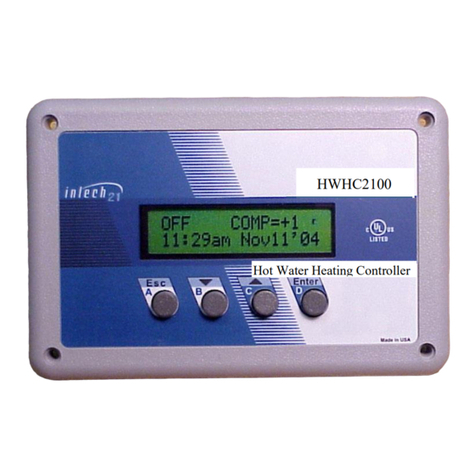
intech 21 OPLC-2100 User manual

OPLC-2100 Operation Manual
CONFIDENTIAL
21 Harbor Park Dr. N, Port Washington Phone: 516.656.72211 Fax: 516.626.7201
1
One Pipe Local Controller OPLC2100
1. Introduction
The One Pipe Local Controller OPLC-2100 V3.26 (Fig 1) has been designed to provide control of the Steam Zone Valve in
One Pipe Heating System to regulate the amount of heat (thermal energy) supplied to a building, as well to provide control a
Steam Boiler. On the Steam Boiler application the OPLC-2100 is equipped an auxiliary board to supply 4 –20ma interface
to control the Boiler’s actuator. On this document we will describe the Steam Boiler Control further called as “Boiler+”.
OPLC-2100 works as a standalone controller or can be connected to a Local Server, which furnishes the additional
parameters adjustments to OPLC-2100 based on apartments real time temperature reading in order to improve the heating
supply efficiency and avoid apartment over/under-heating. When the OPLC-2100 is connected to the Local Server it can be
monitored and controlled from the local Intranet and/or Internet with appropriate authentications. On all applications
automatic control of the main parameters in accordance with operation settings and measured temperatures/pressure to
achieve optimal heating delivery and reduce fuel losses.
Figure 1. OPLC2100. Front view
The OPLC-2100 features:
Adjustable Day and Night modes of operation.
Adjustable Winter and Summer modes of operation.
Programmable Heat Up and Cool Down set points.
Morning Boost period up to 120 min.
Provides compensator control for unusual weather conditions
Measures and displays outdoor and heating system sensors temperature.
Measures and displays Boiler’s steam pressure.
Sensors malfunction processing and indicating (open/short situation).
Displays the control cycle parameters and valve status.
Adaptable to different types of standard temperature and pressure sensors, and valve motors.
Simple calibration procedure for the temperature and pressure sensors.
Internal real-time clock/calendar with backup battery.
Automatic storage of setup values. No loss of setup values or mode of operation if power is OFF for extended time.
Automatic Daylight Saving Time clock adjustment.
Locally controlled by the four-button keypad and convenient menu.
Password protection for the critical settings.
Remotely controlled and/or monitored through the RS485 interface.
PID controlled analog output 4-20mA or digital potentiometer for flame modulations to maintain the
required steam pressure during the boiler ON cycle.

OPLC-2100 Operation Manual
CONFIDENTIAL
21 Harbor Park Dr. N, Port Washington Phone: 516.656.72211 Fax: 516.626.7201
2
2. Operation Basics
The OPLC-2100 controller (“Boiler+” version) is designed to provide automatically regulated heat distribution by cycling a
boiler on and off and modulating the flame. The controller continuously calculates the amount of heat requested by the
building taking into account the outdoor temperature, heating system temperature, boiler’s steam pressure and selected
settings. Then the controller assumes that this requested heat value is actually the average heat amount, which must be
delivered to the building. Knowing the CYCLE setting the controller calculates the ‘ON’part of the cycle and controls the
flame modulation. To achieve an optimal performance of the heating system a discrete Proportional-Integral-Derivative
(PID) algorithm is implemented in the “Boiler+” system. Based on generic control loop feedback mechanism the PID
controls flame modulation.
It makes sense to have some constant period of the boiler operation (CYCLE), which, in turn, is divided to ‘ON’ part of
the cycle, during which the boiler is on, and the rest of the cycle, when the boiler is off (‘OFF’ part). In such a scheme of
boiler operation the average amount of heat delivered to a building is proportional to the ratio of’ON’and CYCLE values.
In brief, the controller calculates the heat amount requested by the building (percents) and transforms this value to the
parameters of the boiler cycle (minutes). Main goal of the PID control is supporting stable value of the boiler’s pressure
which is define by pressure set point and three PID parameters. Controller attempts to correct the error between measured
pressure and desired pressure set point by calculating and then outputting corrective action (open or close ) to the boiler’s
Gas Valve actuator. Special sequence of the functionality for the “Boiler+” is implemented to provide proper control of the
boiler during the ‘ON’ part of the Cycle (Fig.3). The flame modulation can starts after the certain period of time called
“Purge” when Gas Valve position achieves special set point (called ‘LFR’ – Low Frame Rate) and after ‘Purge Delay’ set
point. Switch from the ‘ON’ part of the cycle to the ‘OFF’ part of the cycle required “Post Purge” period which includes
time for moving Gas Valve from a point where it was during on the ‘ON’ part to the LFR set point and shat down the boiler.
After ‘Post Purge Delay’ the Valve returns to the zero position. The PID control is active on the Heat Up state and D
(N):Norm state of the Heating Cycle (Fig.3).
3. Controls
The four-button keypad and 16 characters by 2 lines LCD backlit display can be found on the front panel of the
OPLC-2100. These controls provide full local management of the system. Operator can read system status information (e.g.
temperatures, pressure, cycle parameters, and alerts), set the operational modes, and change settings. The control keypad
consists of four pushbuttons: Escape (Esc), Down (), Up (), Enter (Enter). The keys are also marked with letters A, B,
C, D to simplify the passwords memorizing. Holding down the () or () keys will speed up decrement or increment of
setting parameters.
Upper line of the display shows current mode of operation (AUTO, MANUAL, or SET), percentage of heat
requested, and the operational status. Lower line is dedicated to show system status information and setup dialog.
4. Menu
The process of interaction is menu driven. Menu chart is shown on Fig 2. The menu is organized in convenient and
logical way, and follows a simple set of rules.
The menu chart is organized as a set of menu boxes. To navigate between the boxes one should press
Enter key to move to the right on the chart and Esc key to move backward.
Each box contains one or more menu items. To switch between the items inside a box one should press Up
or Down keys.
Each item represents one menu entry: select a setting to change, enter a new setting value, change mode of
operation etc.
If the item contains "NEW" word then the new value has to be entered: Pressing Up and Down keys
change the value. Pressing the Enter key accepts the new value. Esc key rejects the new value, and leaves
the setting unchanged.
If a password is required then one should enter a certain key sequence. For convenience the passwords are
coded as a sequence of letters (e.g. DDBBCBA).
Starting point of the menu is the topmost item of the leftmost box, which is a current cycle parameters line
in the chart. If lost in the menu just press Esc repeatedly, until the display shows something like:
"Cyc:29/61 ON:12”. You are now in the upper left corner of the menu chart.

OPLC-2100 Operation Manual
CONFIDENTIAL
21 Harbor Park Dr. N, Port Washington Phone: 516.656.72211 Fax: 516.626.7201
3
Fig 2. OPLC-2100 Menu Chart
(Boiler+ Configuration)
Cyc:29/61 ON:12
SET OPER MODE
NEW Mode=AUTO
2.8psi FR=17%
NEW Mode=MAN ON
Compensator=+1
NEW Mode=MAN OFF
10:25am Aug10'07
NEW Mode=MAN SET
NEW HeatSet=56%
OD Temp = 42°F
NEW Mode=OFF
SYS Temp=120°F
Enter for more..
SET Compensator
NEW Compens=+1
CACADCB
SetConfiguration
Password1:*******
NewConf-Boiler+
OPLC-2100/644
CACADCB
NewConf-Boiler
VERSION v3.26
SETUP
Password1:*******
SET D:Mild
NEW D:Mild =60
SYSConf-Boiler+
SET N:Mild
NEW N:Mild =25
TotalTm=103hrs
SET N:Stbk
NEW N:Stbk =20
HeatngTm=42hrs
SET Heat Gain
NEW Ht Gain=1.0
D:Mild = 55°F
SET Comp Snstvty
NEW CompSens=1.0
N:Mild = 5°F
SET Boost Span
NEW BoostSpn=0
N:Stbk = 15°F
SET BoostAdvance
NEW Boost Adv=0
D:ICutOff =70°F
SET In D:CutOff
NEW D:CutOff=70°
N:ICutOff =60°F
SET In N:CutOff
NEW N:CutOff=60°
D_Band = 2.5°F
SET D_Band
NEW D_Band= 2.5°F
InDoorTemp=90°F
SET Day Begin
NEW Begin=5:00am
Heat Gain=4.0
SET Day End
NEW End=10:00pm
Comp Snstvty=1.0
SET WntrBegin
NEW WrBeg=Oct.15
Heat Limit=100%
SET WinterEnd
NEW WrEnd=May.15
MotorType=30s
SET Cycle Span
NEW Cycle=60min
BoostSpan=30min
SET Heat Limit
NEW Heat Lim=80%
BoostAdvance=10m
SET Motor Type
NEW MotorTp=30s
Day Begin=5:00am
SET HeatUpStp
NEWHeatUpSP=125
Day End=10:00pm
SET CoolDwnStp
NEWCoolDwnSP=120
WntrBegin=Oct.15
SET HeatUpTm
NEWHeatUpTm=5m
WinterEnd=May.15
SET CoolDwnTm
NEWCoolDwnTm=5m
CycleSpan=30min
SET TIME & DATE
SET Minute
NEW Minute=56
HeatUpSetP=125°F
SET Hour
NEW Hour=2PM
HeatUpTime=5m
SET Month
NEW Month=12
CoolDwnTime=5m
SET Date
NEW Date=5
CoolDwnSetP=120°F
SET Year
NEW Year=2
PID_P = 1.0

OPLC-2100 Operation Manual
CONFIDENTIAL
21 Harbor Park Dr. N, Port Washington Phone: 516.656.72211 Fax: 516.626.7201
4
PID_I = 0.7
DDBBCBA
PID_D = 0.0
SET CALIBRATE
Password2:*******
CAL OUTDoorTemp
NEW ODTAdj=0.
IntSumErr=-7.1
CAL SYStemTemp
NEW SYSTAdj=0
Correction=-6.6
SET Com.ID
NEW Com.ID=3
SetPSenser@4ma
NEWPSes@4ma=
FiringRate=64.3%
SetPSenser@20ma
NEWPSes@20ma=
LowFlameRate=15%
MAINTENANCE
Password1:*******
SET PID_P
NEW PID_P= 0.7
CAL PRESSURE
NEW PRAdj=0.1
PressurStp=5.2psi
=3.0psi
CACADCB
SET PID_I
NEW PID_I=0.5
CAL ValveCloseP
NEW Cadj=572
SampleRate=12sec
SET PID_D
NEW PID_D=0.2
PurgeDelay=30sec
SET PurgeDelay
NEW PurgeD=30sec
PsPurgeDly=15sec
SET PsPurgeDly
NEW PPurgeD=20sec
PSen@4ma =-15psi
SET Pressure Stp
New Pres=5.6psi
PSen@20ma = 15psi
SET LowFlame LVL
NewFlameLvl=15%
Pressure=4.9psi
SET SamplingRate
NewSampleR=12sec
SYS Temp=120°F
OD Temp = 42°F
Com.ID=1
Fig.3 Typical track of the Fuel Valve position for a regular Heating Cycle.
(‘OFF’ part of the Cycle is not shown)
| Purge state | HeatUp | D:Norm state | PPrg (Post Purge) state
| | state | ~ ~~ ~~ | |
Valve Position -------|--------- |~ ~ ~ ~~ ~ ~~~ ~~~~~~~~~~~~~---------------------------|
When the Pressure | | ~ | |
Set-Point is reached | ~ | ~ | |
| | ~ | | |
| | ~ | | |
| | ~ | | |
| LFR ________________~ | | _______________LFR |
| | | | | | | |
| | | | | | | |
| | | | | | | |
| | | | | | | |
| | | | | | | |
|-----|---------------|----------|---------------------------------|----- |--------------|-----|
| Ramp| Purge Delay | | |Slope1|PostPurgeDelay|Slope2
*Boiler *Boiler
’ON' 'OFF'

OPLC-2100 Operation Manual
CONFIDENTIAL
21 Harbor Park Dr. N, Port Washington Phone: 516.656.72211 Fax: 516.626.7201
5
LFR–Low Flame Rate. Sign ‘~’ shows that PID control of the Gas Valve movement is altering.
5. Operational States and System Information
5.1. Upper Line of the Display
The OPLC has five Modes of Operation: AUTO, SET, MANUAL ON, MANUAL OFF and OFF.
The Mode can be selected by operator or remotely. Depending on the Operation Mode and many parameters the controller can be in one of the Operational
States. The Mode and the Operational State are permanently displayed in the upper line of the LCD as follows:
LCD Indicator
Mode of
Operation
Upper line
begins with
Description
Possible Operational States
(indicate on the right corner of the upper line)
OFF
OFF:
PPrg (Post Purge)
Auto
AUTO: hh%
AUTO^max%
Calculated Target Heat Amount to be
delivered, ‘hh’ in the range of (0%-100%)
Summer, D:Mild, N:Mild, D:ICOFF, N:ICOFF, N:Stbk, D:Norm,
N:Norm, HeatUp, CoolDn, Boost and FailSf Purge, PPrg
Manual Set
SET:hh%
Target Heat Amount to be delivered,
Purge, PPrg
MAN ON
MANUAL ON:
Sets Gas Valve to selected position
Purge,PPrg
MAN OFF
MANUAL OFF:
Unconditional shutting down the Boiler.
PPrg
.
Notes: hh –Target Heat Amount (‘hh’ in the range of 0%-100%);
^max –Heat Amount is limited by Heat Limit Set Point.

OPLC-2100 Operation Manual
CONFIDENTIAL
21 Harbor Park Dr. N, Port Washington Phone: 516.656.72211 Fax: 516.626.7201
6
5.2. Operational States and Bottom Line of the Display
Upper Line of LCD
Bottom line of LCD
Description:
Operational
Mode
Operational State
OFF
PPrg (Post Purge)
aa.a ps FR=yy.y%
When mode is changed to ‘OFF’ operation Gas Valve moves to Close position. Where:
aa.a ps –boiler’s pressure (in psi), FR (Firing Rate) - current Gas Valve position (in
percents)
ttsec LFR=zz.z%
When FR == LFR set point then Boiler shats down. Gas Valve will stay on LFR position
until -Post Purge Time Delay (ttsec) expired.
aa.b ps FR=0.0%
After Post Purge Delay the valve is start moving to 0.0% position. aa.b ps - pressure
AUTO:xx%
AUTO:0%
AUTO:100%
D:Norm, N:Norm,
N:Stbk,
Cyc:A/B ON:C
or
Cyc:A/B OFF:D
variants:
1.Cyc:0/CL OFF^CL
2.Cyc:CL/0 ON^CL
Regular Cycle. CL (Cycle Length) is A + B. in minutes.
A = Calculated time amount the boiler must be ‘On’; B = CL –A;
C = Current minutes boiler is ‘On’ or D = = Current minutes boiler is ‘Off’
0% heat to be delivered , Boiler is OFF more then CL minutes;
100% heat to be delivered, Boiler is ON more then CL minutes;
(sine’^’= shows that the boiler stays on ‘On’ or ‘Off’ more time then Cycle length)
AUTO:0%
D:Mild, N:Mild,
D:ICOFF,N:ICOFF
Cyc:0/CL OFF:D,
Cyc:0/CL OFF^CL
Mild Weather or InDoor CutOff.
0% heat to be delivered, Boiler is OFF D minutes (D < CL);
0% heat to be delivered, Boiler is OFF more then CL minutes;
AUTO:100%
Boost
Span=BSm ON:BT
Morning Boost. BS = Boost Span. BT = Current minutes boiler is ‘On’.
AUTO:xx%
Purge
aa.a ps FR=yy.y%
ttsec LFR= zz.z%
Boiler is On. Gas Valve moves toward to LFR. When FR riches LFR, then starts Purge
Delay down counter (ttsec). Purge is finish when ttsec == 0.
AUTO:xx%
PPrg
aa.a ps LFR=yy.y%
ttsec LFR=zz.z%
aa.b ps FR=0.0%
See PPrg on the ‘OFF’ operation description

OPLC-2100 Operation Manual
CONFIDENTIAL
21 Harbor Park Dr. N, Port Washington Phone: 516.656.72211 Fax: 516.626.7201
7
AUTO:xx%
HeatUp
ExtCycle ON:E
Appear after Purge state if SYSTemp < HeatUpSP. Controller will be on HeatUp state
either SYSTemp > HeatUpSP or HeatUpTime is expired.
E = Current minutes boiler is ‘On’.
AUTO:xx%
CoolDn
ExtCycle OFF:E
Appear after ‘OFF’ part of Cycle (on D/N:Norm state) if SYSTemp > CoolDwnSP.
Controller will be on CoolDn state either SYSTemp < CoolDwnSP or CoolDwnTime is
expired. E = Current minutes boiler is ‘Off’.
AUTO:50%
FailSf
Cyc:F/F ON:G
Cyc:F/F OFF:E
Fail Safe - Out Door Temperature Sensor fail, the controller sets 50% heating Cycle.
F = CL/2; G = Current minutes boiler is ‘On’ or E = Current minutes boiler is ‘Off’.
AUTO:0%
Summer
No Modulation
No-heating season
M_Set:xx%
Purge
aa.a ps FR=yy.y%
ttsec LFR = zz.z%
Same as for the AUTO mode of operation (see Purge description above)
PPrg
aa.a ps LFR=yy.y%
ttsec LFR=zz.z%
aa.b ps FR=0.0%
See PPrg on the ‘OFF’ operation description
Cyc:A/B ON:E
or
Cyc:A/B OFF:H
Regular Cycle. Same as for the AUTO mode of operation.
Manual OFF
PPrg
aa.a ps LFR=yy.y%
ttsec LFR=zz.z%
aa.b ps FR=0.0%
(see Post Purge description above)
Manual ON
Purge
aa.a ps FR=yy.y%
ttsec LFR=xx.x%
(see Purge description above)
SET Firing Rate
Option: Press ‘Enter’ at any time and ‘Down’ key (or ‘UP’ key several times in Manual
ON only). (f1M_ON ==1)
aa.apsi SFR=nn.n%
Press ‘Enter’
(f1M_ON ==1)&&(fM_OnPruf ==1)
aa.apsi SFR=mm.m%
Press ‘Up’ or ‘Down’ Key
bb.cpsi FR=yy.y%
Press ‘Enter’ or ‘Esc’ to quit from the option
Press ‘Up’ or ‘Down’ Key To display other information’s (scroll information).
1. Option –possibility to change Firing Rate on +/- 0.8% by pressing ‘Up’ or ‘Down’ key;
(SFR –Set Firing Rate (increment/decrement) current Gas Valve position.)
(FailSf )


OPLC-2100 Operation Manual
CONFIDENTIAL
21 Harbor Park Dr. N, Port Washington Phone: 516.656.72211 Fax: 516.626.7201
9
5.3 System Status Information
All operational parameters and useful information can be seen on the low line of the LCD display by using
Up/Down and Enter keys (see Fig.2 left corner). The following information can be selected (by pressing Up or Down key)
for displaying on the lower line of the LCD:
Status Information
Example
Description
Heating Cycle Parameters
Cyc:19/41 ON:12
The number before slash: ‘ON’ part of the cycle, minutes. The number after
slash: ‘OFF’ part of cycle period, minutes. The number after ON: current
time of the ‘ON’/’OFF’ part of the cycle, minutes. (The cycle length is
60minutes).
Pressure and Firing Rate
4.2ps FR=17.8%
The pressure is represented in psi. The Firing Rate (FR) is percent of the
Gas Valve opening.
Compensator
Compensator=+1
Indicates the COMPENSATOR setting.
Time and Date
10:25am Sep10'08
Current time and date. The "am/pm" displayed with capital letters when
Daylight Saving Time is in effect.
Outdoor Temperature
OD Temp=52°F
Temperature at the RTD outdoor sensor (="fail" if temperature sensor
malfunction).
System Temperature
SYS Temp =120°F
Temperature at the RTD sensor installed on the pipe segment farthest piping
distance from the boiler and above the water line of the boiler.
(="fail" if temperature sensor malfunction).
More information
Enter for more…
Pressing the ‘Enter’ key will show additional information (see Fig.2 left
corner).
Dependent of the Operational Mode and Operational State contents of two first rows of the Table can be change and will
appear us follows:

OPLC-2100 Operation Manual
CONFIDENTIAL
21 Harbor Park Dr. N, Port Washington Phone: 516.656.72211 Fax: 516.626.7201
10
6. Mode of Operation
The upper line of the display shows the current mode of operation (AUTO, SET, MANUAL ON, MANUAL OFF, and
OFF), indicates amount of heat (thermal energy) to be supplied during AUTO or SET operation. The right corner of the
upper line indicates the current Operational State. (Please refer to the detailed description on section 10).
The OPLC-2100 operates in one of the following modes:
Operation
Mode
Description
AUTO
The controller provides automatically regulated heat distribution by cycling a boiler on and off and
modulating the flame cycling in accordance with the measured temperatures, time of day, and selected
settings. This mode is designed to be the main mode of operation. If the system settings are set
properly, then there is no need in manual intervention in the system performance virtually at any
weather condition.
In AUTO mode the controller distinguishes three periods of day:
1. Morning Boost period begins at 5:00AM. The Morning Boost setting defines the boost duration.
During the Boost period the Boiler will deliver maximum amount of the thermal energy. (By using
‘Boost Advance’ set point operator can shift start of the Boost period for early time)
2. Daytime period (from boost period end to 10PM). Normal daytime operation.
3. Nighttime period (10PM to 5AM). The amount of delivered heat can be reduced against the daytime
period, as defined by the COLD NIGHT and NIGHT SETBACK settings.
Note:
If Out Door Temperature has been reached Day Mild or Cold Night Set Point the Boiler will be shut
down via special procedure named “Post Purge” (which is will be indicated on the right corner of the
upper line of the LCD as ‘PPrg’ operational state). ‘D:Mild’or ‘N:Mild’operational state will be
displayed (for DAY/NIGHT mild weather) after Post Purge procedure has finished. In the summer
season and InDoor CutOff the Boiler will be shut down in the same way and operational state will be
indicate as ‘Summer’ or ‘D:ICOFF’(‘N:ICOFF’) accordingly. On this situation any heating process
can be controlled by entering SET, MANUAL ON, MANUAL OFF, and OFF operations.
(For the detailed description of the Operational states, please refer to section 10).
SET
The amount of delivered heat is set manually to the desired value (0 to 100%). The heating cycle is
fixed and doesn’t change. This mode can be useful at some circumstances (e.g. if the temperature
sensor failed and automatic control is impossible)
MAN ON
This operation allows setting the Gas Valve to selected position or manually modulating the flame.
Can be used on emergency or adjustment period.
MAN OFF
Unconditional shutting down the Boiler by meaning of the Post Purge procedure. This mode can be
used in emergency if one wants to shut down the boiler.
OFF
One should select SET OPER MODE item in the menu to change the mode, press Enter, then, with Up or Down key select
a new mode, and press Enter. When the SET mode is selected, the new heat amount percentage must be entered. During the
Post Purge procedure (‘PPrg’ operational state) new operation can not be entered.

OPLC-2100 Operation Manual
CONFIDENTIAL
21 Harbor Park Dr. N, Port Washington Phone: 516.656.72211 Fax: 516.626.7201
11
Fig 4. Heat Request vs. Outdoor Temperature curves.
(Mild Weather=55, Compensator=0)
Fig 5. Heat Request vs. Outdoor Temperature curves.
(Mild Weather=55, Heat Gain=3.0, Compensator Sensitivity=3.0)

OPLC-2100 Operation Manual
CONFIDENTIAL
21 Harbor Park Dr. N, Port Washington Phone: 516.656.72211 Fax: 516.626.7201
12
7. Compensator
The COMPENSATOR setting provides manual adjustment to the amount of heat being delivered to compensate the
influence of some weather conditions (e.g. strong wind).
The controller, when calculating the amount of requested heat, subtracts the Compensator value from the outdoor
temperature multiplied by the Compensator Sensitivity thus correcting the value of requested heat.
The COMPENSATOR range: -5 to +5 units. Positive values of the setting increase heat delivery, while negative
values reduce it. Default value is 0.Fig.5 illustrates the Compensator's influence on the control curve.
This is the only setting, which is not protected by the password
8. Operation Settings
To provide correct and reliable operation of the OPLC-2100 the operational parameters must be set properly. The
parameter section of the menu is divided in two parts (SETUP and MAINTENANCE ). Each part protected with a
password. Use following tables as guidelines when selecting parameters' values:
SETUP (password: CACADCB)
Setting
Description
D:Mild (DAY
MILD WEATHER)
The controller issues heat request of 0% when the outdoor temperature is higher than this set
point. Range: 40° to 80 °F with 1° step. Default value is 55°F.
N: Mild (NIGHT
MILD WEATHER)
If the outdoor temperature is lower than this setpoint and the time is between 10PM and 5AM,
then the heat request value is corrected in accordance with the NIGHT SETBACK setting.
If the outdoor temperature is higher than this setpoint and the time is between 10PM and 5AM,
then the heat request is set to 0%.
Range: 20° to 60 °F with 1° step. Default value is 40°F.
N:Setbk (NIGHT
SETBACK)
The controller adds to the outdoor temperature the NIGHT SETBACK value thus correcting the
heat request value to reduce heat delivery during the nighttime.
Range: 0° to 80 °F with 1° step. Default value is 10°F.
Heat Gain
Determines the slope of the control curve: Heat Request vs. Outdoor Temperature.
Fig 3 represents the family of control curves with Heat Gain as parameter when
COMPENSATOR=0 and NIGHT SETBACK=0.
Positive Compensator values shift a curve up, negative - down.
Positive Night Setback values shift a curve down.
Range: 1.0 to 50.0 with 0.1 step. Default value is 1.0
Comp Snstvty
Determines the weight of the compensator's unit.
Range: 0.1 to 9.9 °F/unit with 0.1 step. Default value is 1.0
Boost Span
Morning boost time span. The controller boosts heat only with AUTO mode in effect.
Range: 0, 30, 60, 90 or 120 minutes (0 means no boost) Default value is 0.
BoostAdvance
This parameter determines early (before 5:00am) boost time. Default value is 0.

OPLC-2100 Operation Manual
CONFIDENTIAL
21 Harbor Park Dr. N, Port Washington Phone: 516.656.72211 Fax: 516.626.7201
13
In D:CutOff
(In Door Day
Temperature
Cutoff)
The controller closes the valve completely when the In Door temperature average (supplied from
host computer) is higher than this set point during the Day - time between Day Begin and Day
End (D:ICOFF state). Range: 40 to 90 °F
In N:CutOff
(In Door Night
Temperature
Cutoff)
If the In Door temperature average (supplied from host computer) is higher than this set point
and the time is between Day End and Day Begin, then the valve will be closed completely
(N:ICOFF state). Range: 40 to 80 °F
D_Band
Used along with ‘In Door Temperature’ parameter and ‘In Door Day/Night Temperature Cutoff’ Set
Point. This parameter defines the allowable delta between the actual In Door Temperature and
Cutoff Set Point.
Range: 0.1°F to 19.9°F with 0.1°F steps
Day Begin
Hours and minutes (with 10 minutes step) when Day Begins
Day End
Hours and minutes (with 10 minutes step) when Day Ends
WinterBegin
Month and Day when Winter Begin (dependent of the region)
WinterEnd
Month and Day when Winter End (dependent of the region)
Cycle Span
Heating cycle period, minutes.
Range: 20 to 90 minutes, Step 10minutes. Default value is 60 minutes
Heat Limit
This parameter overrides the system calculated ‘ON’ period if ‘ON’ bigger than ‘Hit Limit’
Default value is 100%.
Motor Type
Motorized valve nominal timing (in seconds) for 90° or 160° stroke.
Range:{15,30,45,60,72,90,144,180,240}seconds. Default = 30seconds.
HeatUpStp
New cycle will comment when the system temperature on the Cold Pipe Temperature Sensor
reaches this set point (please see diagram on Figures 5-7, red line).
Range: 40 to 240°F, Step 1°F Default value is 125°F
CoolDwnStp
Heating can start if the system temperature drops below this set point (checks each time after
current cycle finished). (please see diagram on Figures 5-7, blow line).
Range: 40 to 240°F, Step 1°F Default value is 120°F
HeatUpTm
Controller can start new cycle either SYSTemp > HeatUpSP or HeatUpTm is expired.
Range: 0 to 90 minutes, Step 1minute. Default value is 5minutes.
CoolDwnTm
Heating can start either SYSTemp < CoolDwnStp or CoolDwnTm is expired.
Range: 0 to 90 minutes, Step 1minute. Default value is 5minutes.
TIME & DATE
The submenus of this setting allow setting up the internal real time clock of the controller. It is
essential to have the clock set properly, because the Boost, Night Saving modes and Daylight
Saving Time Adjust rely on the clocks accurate setting.
CALIBRATE
Submenu for Calibration of Temperature and Pressure Sensors. Uses to calibrate a current for
motorized valve. (Please see chapter #10)
Com.ID
Each OPLC-2100 connected to the local server via the RS485 bus. To establish proper connection
the controller should have a unique communication address (ID).
Range: 1 to 99.

OPLC-2100 Operation Manual
CONFIDENTIAL
21 Harbor Park Dr. N, Port Washington Phone: 516.656.72211 Fax: 516.626.7201
14
‘MAINTENANCE’menu contains data to control the Motorized Gas Valve by meaning of boiler’s pressure and PID
algorithm .
MAINTENANCE (password: CACADCB)
Setting
Description
PID_P
‘P’ coefficient for PID algorithm. Range: 0 to 99.9. Default = 5. Step 0.1.
PID_I
‘I’ coefficient for PID algorithm. Range: 0 to 99.9. Default = 1 .Step 0.1.
PID_D
‘D’ coefficient for PID algorithm. Range: 0 to 99.9. Default = 0. Step 0.1.
PurgeDelay
Purge Delay (please see Fig.) Range: 0 to 255 sec. Default = 30 sec. Step 1sec.
PsPurgeDly
Post Purge Delay (please see Fig.) Range: 0 to 255 sec. Default = 15 sec. Step 1sec.
Pressure Stp
Maximum boiler’s pressure set point. Range 0 to 35 psi. Default = 2psi. Step 0.1psi
LowFlameRate
Starting point before Flame modulation. can start and Heating Cycle can complete. Range 0% to 100%.
Default = 15%. Step 1%.
SamplingRate
PID algorithm sampling rate. Range 1 t0 255 sec. Default = 12 sec. Step 1sec.
9. High Pressure Processing
There are three operational modes the controller can react on the High Pressure: ‘AUTO’, ‘MAN SET’, and ‘MAN ON’.
In the ‘AUTO’ and ‘MAN SET’ mode of operations the controller will finish current operational Cycle and will not start the
next until (PRESSURE + 2) <= PRESSURE_SP (0.2 psi hysteresis).
In the ‘MAN ON’ mode the controller will close the fuel valve to 0%.If the boiler was turned OFF before changing the
operational mode to” MAN ON” it wouldn’t turn the boiler ON until the pressure become less than the Set-Point minus
.2psi
High Pressure Indication on the LCD
f6HighPressure==1
AUTO
MAN SET
MAN ON
Top Line
AUTO:75% D:Norm
SET:25%
MANUAL ON:
Bottom Line
Cyc:45/15 OFF-hP
Cyc:15/45 OFF-hP
aa.a ps OFF-hP
f2PressureFail==1
Top Line
AUTO:75% D:Norm
SET:25%
MANUAL ON:
Bottom Line
Cyc:45/15 PS_Fail
Cyc:15/45 PS_Fail
PS_Fail OFF
10. Calibration Procedures
The temperature sensor, pressure sensor, and motor current loop interface must be calibrated after the initial system
installations or after the parts replacement. The OPLC-2100 facilitates the calibration procedure. To enter the calibration
section of the menu, select SET CALIBRATE and then enter password. Following table provides explanations for the
calibration procedure.
1. Select CAL OutDoorTemp. and press Enter
2. The upper line of the display indicates mode of operation (“CAL”) and

OPLC-2100 Operation Manual
CONFIDENTIAL
21 Harbor Park Dr. N, Port Washington Phone: 516.656.72211 Fax: 516.626.7201
15
Outdoor Temperature
Sensor Calibration
shows actual reading of the temperature sensor: " ODT=xx.y° ".
3. The lower line of the display shows possible adjustment for example
“NewODTAdj=0.1°”
4. Press Up or Down key to make the ODTemp equal to the real outdoor
temperature, measured by the reference thermometer.
5. Press Enter.
System Temperature
Sensor Calibration
1. Select CAL SystemTemp. and press Enter
2. The upper line of the display indicates mode of operation (“CAL”) and
shows actual reading of the temperature sensor: " SYST=xx.y° ".
3. The lower line of the display shows possible adjustment for example
“NewSYSTAdj=0.1°”
4. Press Up or Down key to make the SYST equal to the real system
temperature, measured by the reference thermometer.
5. Press Enter.
Set Pressure Sensor Value
for minimum current (4ma)
1. From Calibration Menu Select SetPSensor@4ma and press Enter
2. The upper line of the display indicates mode of operation (“CAL”)
3. The lower line of the display shows possible adjustment for example
“NewPSns@4ma=-15psi”
4. Press Up or Down key to make desired value, then press Enter.
Set Pressure Sensor Value
for maximum current (20ma)
1. From Calibration Menu Select SetPSensor@20ma and press Enter
2. The upper line of the display indicates mode of operation (“CAL”)
3. The lower line of the display shows possible adjustment for
example “NewPSns@4ma=15psi”
4. Press Up or Down key to make desired value, then press Enter
Pressure Sensor Calibration
1. Select CAL PRESSURE. and press Enter
2. The upper line of the display indicates mode of operation (“CAL”) and
shows actual reading of the pressure sensor: " PRS=xx.y psi ".
3. The lower line of the display shows possible adjustment for example
“New PRSAdj=0.1°”
4. Press Up or Down key to make the PRS equal to the real boiler pressure,
measured by the reference pressure transducer.
5. Press Enter.
Motor current loop interface
Calibration
From ‘MANUAL CLOSE’ Operation when Valve is closed (VALVE POS=0%):
1. Connect ampere meter between the ZVLC’s terminal pin#2 (CLOSE) and
motor connector (in case of absent the motor , 100oHm resistor can be
used).
2. Select CAL ValveClosePs. and press Enter
3. The upper line of the display indicates mode of operation (“CALBR”) and
ClsPsCr=4ma.
4. The lower line of the display shows possible adjustment for example
“New VlPsAdj = 1”
5. Press Up or Down key to make the reading 4ma current from the ampere
meter.
6. Press Enter.
Table of contents
Other intech 21 Controllers manuals
Popular Controllers manuals by other brands

Hathorn
Hathorn H12+ Operator's manual
National Instruments
National Instruments NI-488.2M user manual
Mitsubishi Electric
Mitsubishi Electric MELSEC iQ-R Series user manual
Timpdon Electronics
Timpdon Electronics GPRX7 quick start guide

Manley
Manley TUBES RULE ELOP owner's manual
Tusa
Tusa RS-340 owner's manual
