Integral Audio 81S User manual

skill level required applies to
installation difficulty
installation time
2 out of 5
do-it-yourself
1.5 hours
96-02 Z3 ROADSTERS WITH FAC-
TORY INSTALLED ROLL HOOPS
Before You Begin .......................................................................................................................... 2
What’s in the Box .......................................................................................................................... 3
tools You Will need ...................................................................................................................... 4
installation ................................................................................................................................... 5
trouBleshooting ........................................................................................................................... 9
installation Guide
BmW Z3 suBWoofer system
MODEL 81S

Before You Begin
2
• Read this Guide completely BEFORE you begin.
• Disconnect the battery negative terminal while working on the vehicle.
• ALWAYS check behind panels and components before drilling, cutting,
or screwing into any part of a vehicle for any reason!
iMPortant

What’s in the Box
3
suBWoofer
i. Model 81s suBWoofer enclosure [Black or Beige]
ii. custoM aluMaPro alusonic ex8 suBWoofer
iii. hardWare kit
1. Mounting Brackets (2)
2. #10 x 1” Pan Head Sheet Metal Screw (4) [Enclosure Mounting]
3. #10 Fender Washer (4)
4. Rubber Washer (4)
5. #10 Clip-on Nut (4)
6. 10”x12” sheet of cut foam
7. #10 x 3/8” Black Pan Head Machine Screw (8) [Speaker Mounting]
8. Trim Cord
iV. Wiring kit
9. Wiring Harness [Pre-assembled, Pre-terminated]
10. Self-sealing Cable Gland
11. Threadlock Wire Splices (4)
V. integral audio logo Badge
.

tools You Will need
4Images Not to Scale
i. PhiliPs screWdriVer
ii. sockets:
1. 10mm
iii. Wire striPPer
iV. scissors
V. utilitY knife
Vi. sMall flashlight
Vii. dreMel With cutoff Blade [or] hacksaW Blade holder
Viii. Magnetic Parts traY [oPtional]
a.
PreP Vehicle
5
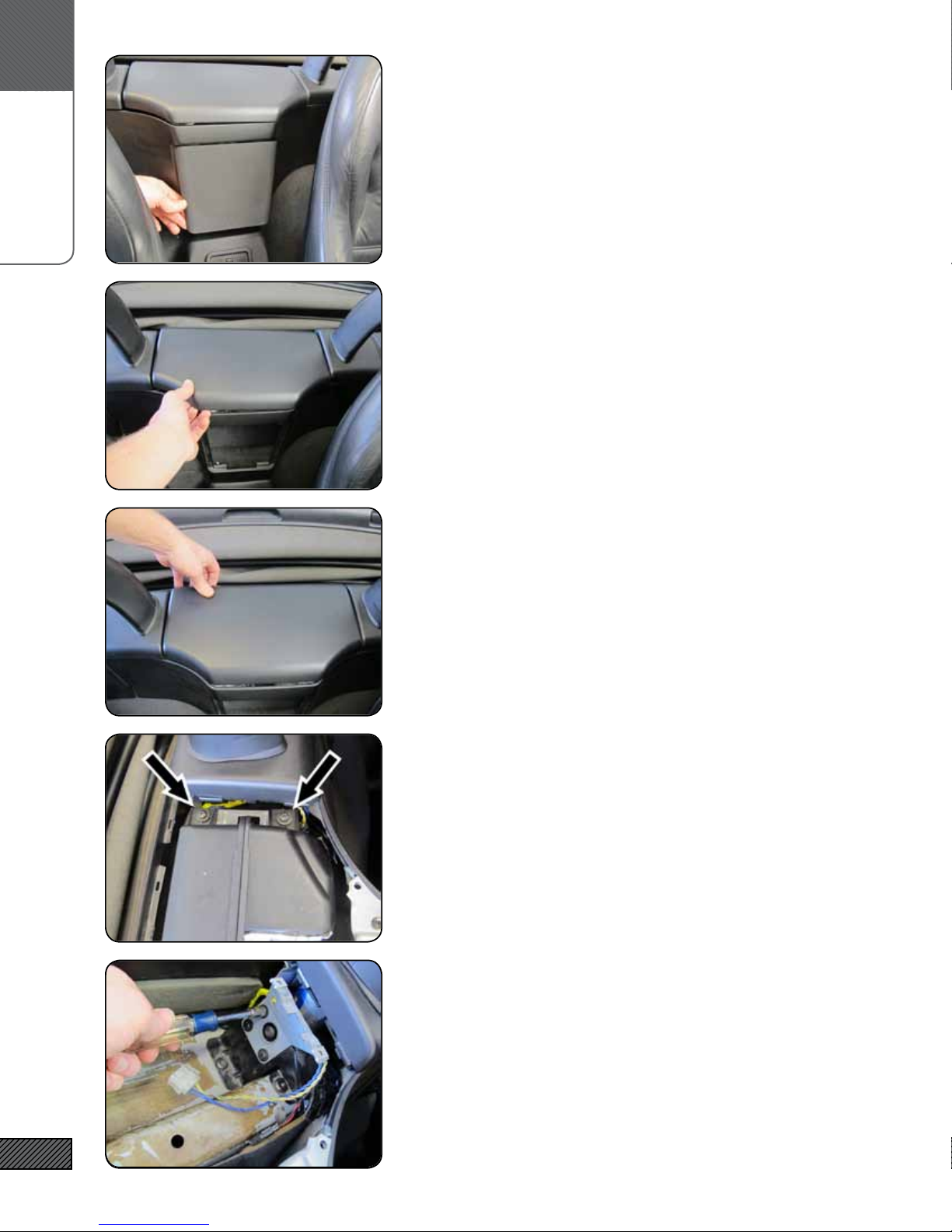
1. reMoVe front grille
Remove the grille from the front of the subwoofer compartment
by pulling out and lifting at the bottom edge.
2. loosen front edge of coVer
Pull up rmly on the front edge of the compartment cover to re-
lease two friction clips.
3. reMoVe coVer
Pull rmly on the rear edge of the cover to release the two rear
clips. Remove the cover.
4. reMoVe enclosure
Remove the (4) Phillips head screws and remove the enclosure.
5. reMoVe Mounting Brackets
Remove both of the existing mouting brackets with a 10mm sock-
et. KEEP THESE MOUNTING BOLTS! You will be re-using them.

a.
installation
6
6. reMoVe Metal flange
Loosen the (2) Phillips screws and remove the metal ange at the
front edge of the compartment and remove the ange.
7. cut off Plastic flange
Using a Dremel or a Hacksaw, cut the plastic ange off ush with
the edge of the compartment. When you are done the front edge
of the compartement should look like the image to the left.
8. cut off rear screW Bosses
Using the Dremel (or hacksaw), cut the screw bosses (the round
things) on the back wall of the compartment ush with the
horizontal rib along the wall. NOTE: these are not present on all
vehicles.
9. slide caBle gland oVer Wiring harness
Remove the thin backing nut from the Cable Gland (leave the
rubber washer in place). Loosen the rounded clamping nut com-
pletely. Insert the stripped wires end of the wiring harness into
the rounded nut end of the cable gland. Tighten/Clamp the gland
down rmly over the wrapped portion of the cable, about 2” from
end of the heatshrink. Insert the stripped wire ends through the
large hole in the side of the enclosure from the inside.
10. install caBle gland
Tighten the backing nut securely - nger tight plus 3/4 turn.
a.
installation
7
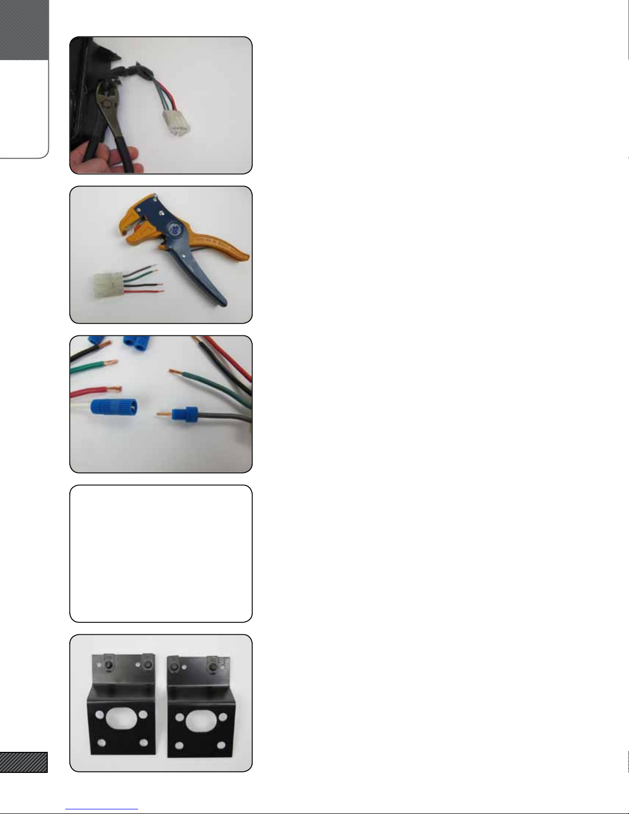
11. cut Plug froM old suBWoofer
Cut the plug off of the old enclosure, at least 3” from the plug.
12. striP Wire ends
Strip 3/8” of insulation from the ends of the plug wires.
13. sPlice Plug to Wiring harness
Unscrew the ends of the threadlock splices. Insert the stripped
end of the wire through the end. Work the wire strands around
the metal cone and into the base of the connector. Hold the wire
rmly in place and tighten the threaded end. Repeat for both
ends of each wire.
CONNECT: Red to Red, Green to Green, Black to Black, and White
to Gray.
14. if Your Vehicle’s Wiring colors are different:
You should be able connect whatever wire is in pin 1 (at square
end of the connector) to White, pin 2 to Green, pin 3 to Black, and
pin4 (at the round end of the connector) to Red. Conrm that the
woofer is operating correctly! If everything is connected correctly
you will get signicant excursion (movement) of the woofer cone.
The BMW documentation does not list the colors and connections
for all vehicles, but this wiring pattern holds for all vehicles that
are listed and has held for every vehicle we have seen.
15. attach cliP nuts to neW Brackets
Slide the clip nuts over the brackets. The clip nuts will be in the
rst and third holes (from front to back) once installed.
alternate Wiring colors!

a.
installation
8
16. attach Mounting Brackets
Using the original mounting bolts, attach both mounting brackets.
Tighten the bolts nger tight - the brackets should not be loose,
but you should be able to move them.
17. teMPorarilY Place enclosure in suB coMPartMent
Slide the enclosure into the compartment, cable gland side rst.
Make sure the wiring and plug are clear of the underside of the
enclosure. The enclosure should sit ush and even with the con-
sole on either side.
18. align the Mounting holes
Use the ashlight to site inside the speaker mounting hole. Use
the #10 x 1” machine screws to alighn the mounting holes and the
clip nuts/brackets by threading them, centering them, centering
the enclosure in the compartment, then removing the machine
screws.
Remove the enclosure. Firmly tighten the bolts securing the
mounting brackets.
19. insert foaM sheet
Place the 10”x12” foam sheet along the bottom of the subwoofer
compartment. The sheet should cover both the upper and lower
portions of the sheet metal and cross beam in the compartment.
20. Mount enclosure
Replace the enclosure.
Place a fender washer and a rubber washer over each of the #10
x 1” machine screws. The rubber washer should be between the
fender washer and the enclosure. Attach the enclosure to the
brackets. Center the enclosure in the compartment and tighen
the screws rmly.
a.
installation
9
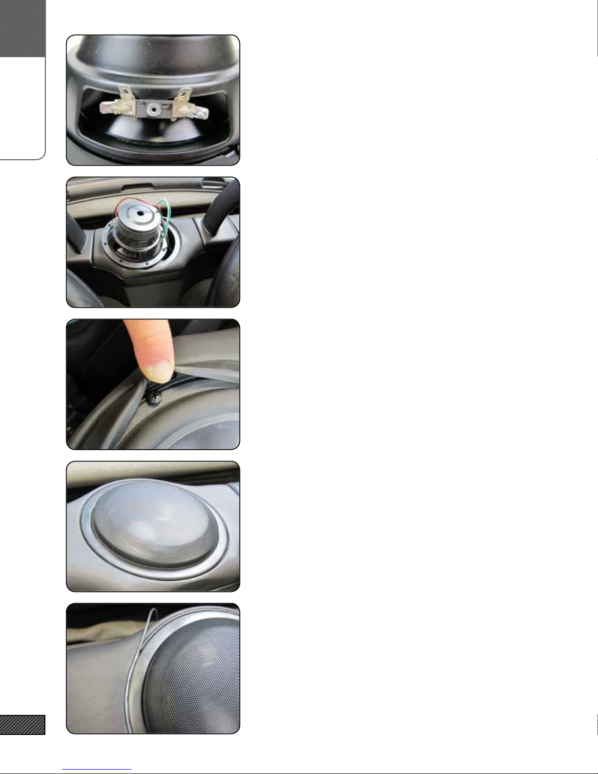
21. identifY Woofer + and -
Look for the “+” and “-” near the terminals tabs on the woofer
22. connect Wiring to Woofer
Connect wires VC1 to + and - of one voice coil, and wires VC2 to
the second coil. It doesn’t matter which coil is 1 or 2 as long as
you observe correct polarity.
DO NOT CONNECT THE COILS IN SERIES. A SERIES CONNEC-
TION RESULTS IN A WOOFER WITH DIFFERENT PARAMETERS.
23. Mount the sPeaker
Rotate the speaker as needed to align the mouting holes with the
threaded inserts in the mounting ange. Attach the speaker with
the #10 x 3/8” black machine screws. Tighten the screws in a star
pattern until the woofer is snug. Tighten rmly but be careful not
to overtighten.
24. install sPeaker grille
The speaker grille is a simple press t - work the grille down into
the outer rubber gasket of the speaker.
25. install triM cord
Lay the trim cord into the gap between the outside of the speak-
er’s rubber gasket and the vinyl top of the enclosure. Carefully
cut the trim cord. Using a blunt at or rounded object, work the
trim cord rmly into the gap.

a.
installation
10
26. enjoY!
That’s it! Afx the Integral Audio logo badge to the front grille
(replace the HK logo if desired). Give your new enclosure a wipe
down with Armor All or your favorite protectant regularly, and
if you are using an aftermarket amplier give your Alumapro
woofer a few hours of moderate volume levels before you really
crank it!

notes
11
notes
Having Trouble? The best thing to do is contact us at support@integralaudio.
com or via the phone number listed on the receipt that was emailed to you.
We’ll get you fixed up ASAP!
trouBleshooting
Other Integral Audio Subwoofer manuals

Integral Audio
Integral Audio 1101S User manual

Integral Audio
Integral Audio 1101S User manual

Integral Audio
Integral Audio PHANTOM User manual

Integral Audio
Integral Audio 1100S User manual

Integral Audio
Integral Audio PHANTOM User manual

Integral Audio
Integral Audio 1101S User manual

Integral Audio
Integral Audio MCSS630SW-RAM User manual

Integral Audio
Integral Audio SoundStage + Subwoofer System User manual


