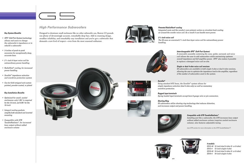
Integral Audio PHANTOM User manual

SKILL LEVEL REQUIRED APPLIES TO
INSTALLATION DIFFICULTY
INSTALLATION TIME
2 OUT OF 5
DO-IT-YOURSELF
1.5 HOURS
2012+ F30 SEDAN
2012+ F80 M3
2012+ F32 COUPE
2012+ F82 M4
BEFORE YOU BEGIN .......................................................................................................................... 2
WHAT’S IN THE BOX........................................................................................................................... 3
TOOLS YOU WILL NEED...................................................................................................................... 5
INSTALLATION:
A. Prep Vehicle ........................................................................................................................ 6
B. Subwoofer ......................................................................................................................... 20
NOTES & TIPS.................................................................................................................................. 28
TROUBLESHOOTING......................................................................................................................... 28
INSTALLATION GUIDE
PHANTOMTM SUBWOOFER SYSTEM
FOR 2012+ BMW 3 & 4-SERIES (F30/F80/F32/F82) ver. 5/20

BEFORE YOU BEGIN
2
•Read this Guide completely BEFORE you begin.
•Disconnect the battery negative terminal while working on the vehicle.
•DO NOT PLACE THE KEY FOB in the vehicle with the battery connected and
the seat airbag wiring disconnected. Doing so will set off the airbag light,
and must be reset by your dealer.
•ALWAYS check behind panels and components before drilling, cutting,
or screwing into any part of a vehicle.
IMPORTANT

WHAT’S IN THE BOX
3
SUBWOOFER
I. INTEGRAL AUDIO PHANTOM™ SUBWOOFER
1. Phantom™ Subwoofer Enclosure
2. Integral Audio Soundstage Series 10” Subwoofer
II. SUBWOOFER HARDWARE
3. Subwoofer Mounting Bracket & Hardware
4. Subwoofer Support Bracket & Hardware
5. Neutrik Quick-connect Subwoofer Terminal & Wiring
6. Subwoofer Cover Grille

TOOLS YOU WILL NEED
4Images Not to Scale
I. TOOLS YOU WILL NEED:
1. Wrenches or Socket Driver & Sockets:
• 10mm deep socket
2. Torx Bits:
• T40
3. Screwdrivers:
• Small Slotted & Phillips
4. Plastic Panel Removal Tool(s)
5. 1/8” Allen (Hex) Wrench
6. Magnetic Parts Tray [Optional]

A.
PREP VEHICLE
5
1. REMOVE BATTERY COVER
Remove battery cover by turning the locking knob and lifting out
the cover.
2. DISCONNECT BATTERY NEGATIVE TERMINAL
Disconnect battery negative terminal with 10mm deep socket.
3. REMOVE TRUNK FLOOR PANEL
Remove the trunk oor panel.
4. REMOVE TRUNK CENTER BIN (STEP 1)
Locate the center pin of the expansion clip at the forward passen-
ger side corner of the liner.
5. REMOVE TRUNK CENTER BIN (STEP 2)
With a plastic panel removal tool, pry out center pin of the expan-
sion clip. Pry out clip base. Remove bin liner.

A.
PREP VEHICLE
6
6. REMOVE TRUNK REAR SILL
Remove the trunk rear sill by removing the (4) center pin expan-
sion clips along the inner side. Lift the lower front edge of the sill
forward to clear the D-rings, then give a rm lift up to release the
friction clips holding the upper portion.
7. FOLD DOWN DRIVER SIDE REAR SEAT
Pull the rear seat release located in the trunk, fold down the driv-
er-side rear seat.
8. REMOVE DRIVER-SIDE REAR QUARTER PANEL TRIM (STEP 1)
Locate the luggage D-ring tie down at the forward driver-side of
the trunk. Pry off the black plastic cover. Remove the Torx T-40
screw. Lift out the D-ring assembly.
9. REMOVE DRIVER-SIDE REAR QUARTER PANEL TRIM (STEP 2)
There are (3) center-pin expansion clips that fasten the rear quar-
ter panel trim to the car - locate & remove the one in the upper
part of the rear cubby area.
10. REMOVE DRIVER-SIDE REAR QUARTER PANEL TRIM (STEP 3)
Then locate & remove the one on the side, under the parcel shelf
area. This one is attached to a plastic bracket. Remove the ex-
pansion clip on the upper portion of the bracket, and leave the
bracket attached to the quarter-panel trim.

A.
PREP VEHICLE
7
11. REMOVE DRIVER-SIDE REAR QUARTER PANEL TRIM (STEP 4)
Then locate & remove the one on the forward edge of the panel,
by the rear seat back.
12. REMOVE DRIVER-SIDE REAR QUARTER PANEL TRIM (STEP 5)
Now remove the trim panel. Start at the forward edge. Lift clear/
free the forward edge from behind the trim at the sides of the
rear seat backs and pull the panel out 4-6 inches.
DO NOT COMPLETELY REMOVE YET.
13. REMOVE DRIVER-SIDE REAR QUARTER PANEL TRIM (STEP 6)
Free panel edge along area (1). Then carefully open the split in
the panel at area (2) by pulling the split directly apart (i.e. not
sideways) and free the panel from around the trunk support arm.
DO NOT COMPLETELY REMOVE YET.
14. REMOVE DRIVER-SIDE REAR QUARTER PANEL TRIM (STEP 7)
Disconnect the plug on the back of the 12V power outlet, then
remove the panel from the vehicle.
15. REMOVE PLASTIC COVER
Remove the nut fastening the plastic cover over the amp with a
10mm socket. Remove the cover.

B.
SUBWOOFER
8
16. LOOSEN WIRE BUNDLE
Loosen/free the 12V power outlet wire bundle by sliding the plas-
tic retaining clip off the mounting stud.
17. SUBWOOFER INSTALLATION
Locate the IASW10T4 Subwoofer, Subwoofer Enclosure, Subwoofer
Hardware Kit, and Speaker Grille.
18. MOUNT THE SUBWOOFER IN THE ENCLOSURE
Connect the Subwoofer Internal Wiring Harness [F30.WH.SUB-INT]
to the Neutrik terminal in the enclosure. Note polarity markings
on the Neutrik terminal! Connect the other end to the subwoofer.
Mount the subwoofer to the enclosure using the eight #10-24 x
1” Button Head Cap Screws and tighten with a 1/8” Allen wrench.
Insert the speaker grille over and around the subwoofer gasket.
19. SUBWOOFER WIRING (NEUTRIK PLUG)
Select the 3ft long Subwoofer Wiring Pigtail from the Subwoofer
Hardware Kit. Connect the Neutrik Speak-on Plug to one end of the
subwoofer wire. Slide the blue chuck (1) over the wire, followed
by the strain-relief bushing (2). Make the positive & negative con-
nections to the plug as shown, tighten the terminals with a small
Phillips screwdriver. Slide the bushing (2) forward and tighten the
chuck (3) onto the plug (3).
20. SUBWOOFER SUPPORT BRACKET
Make sure the sound liner (1) is in place. Install the Subwoof-
er Support Bracket [F30.SUB.HNG.BRKT] (2). The upper end (3)
mounts on the same course-threaded stud as the lower end of the
OEM Amp Relo Bracket. The bracket has three holes for t adjust-
ment, start with the center hole. Fasten with the Flange Nut from
the Hardware Kit. The lower end of the Subwoofer Support Bracket
will be secured underneath the hole shown at (4) in the next step.
NOTE: image shows Soundstage amplier, not included.

9
21. SUBWOOFER MOUNTING BRACKET
Slide the two Clip On Nuts (1) over the holes in the uprights in the
Subwoofer Mounting Bracket. Slide the clips on over the outer edge.
The holes in the clips should align with the holes in the bracket.
Use the 1/4” Serrated Flange Bolts and Nuts to fasten the bracket
through the holes (2). Be sure to fasten the Subwoofer Support
Bracket underneath the hole on the right.
The lower mounting bracket holes are slotted to allow for side-to-
side adjustment if needed. Start with them centered.
22. REMOVE 12V PLUG & PLASTIC COVER PANEL
Remove the 12V plug from the trunk trim panel removed earlier.
Slide/press to one side to release the locking tabs and remove.
Remove the plastic cover panel (2).
23. REMOVE NETTING & BRACKET
Remove the cubby cargo netting & bracket. Use a small screw-
driver to pry open the teeth on the locking push-nuts (1) on both
sides. Remove the bracket. Remove the plastic base clips (2) by
unscrewing the top from the base.
24. REMOVE PLASTIC COVER PANEL
Remove the plastic cover panel (2) by freeing the plastic locking
tabs underneath.
25. SUBWOOFER WIRING (NEUTRIK PLUG)
Place the rear quarter panel trim back in the vehicle. Insert the
subwoofer wiring through the opening where the 12V plug was
removed.
B.
SUBWOOFER

10
26. REPLACE TRUNK TRIM PANEL
Replace the rear quarter panel trim. Start by insterting the for-
ward edge behind the trim at the side of the rear seat backs (1).
Carefully open the slit in the panel (2) and place around the trunk
lid support. Replace the rubber seal (3) over the edge of the panel.
27. CONNECT SUBWOOFER
Connect the Neutrik plug to the subwoofer. Slide the subwoofer
into the compartment. Do not attach the mounting screws yet.
28. FASTEN SUBWOOFER
Once you’ve completed settings and conrmed everything is oper-
ating correctly, fasten the subwoofer. The CAD image at left has
some transparancy so you can see how the bolts attach (1). Use
the two #10-24 x 2.5” Socket Head Cap Bolts and Black Flat Washers.
Make sure the enclosure is fully seated into the compartment.
Press the bolts through the carpet and into the hole until they
make contact with the bracket. Start the threads by hand!
You only need to snug the bolts down, DO NOT OVERTIGHTEN!
29. SUBWOOFER LOGO BADGE
Afx the Rectangular Domed Logo Badge to the subwoofer grille (3)
as shown.
30. ROCK. AND ROLL.
Reinstall remaining trim panels, seats, etc, in the reverse order
they were removed.
That’s it! You should be ready to rock and roll. If you aren’t
seriously impressed by the sound, something is wrong. Trust us
on this. It should be clean, clear, and balanced. If it isn’t, revisit
the steps above or reach out to us for support at 646-926-0011 or
email us at support@integralaudio.com.
[SUBWOOFER O N LY ]
[SUBWOOFER O N LY ]
B.
SUBWOOFER

NOTES
11
NOTES
• SIGNAL SOURCE QUALITY: A poor quality signal will always sound poor no matter how good an audio
system is. If you are using MP3s or home-burned CDs it is critical that you understand the limitations
and impacts of digital compression methods. MP3s at less than 256kbps will have noticeable loss of
quality. Satellite radio is also compressed and will have similar quality issues. Non-commercially ob-
tained music (especially downloaded via P2P le-sharing) recordings are often re-mixed by third parties
and will have been compressed in an unknown and uncontrolled manner. If you want good quality
sound, use only commercially obtained CDs or MP3s compressed at 256kbps or 320kbps.
• FACTORY RADIO SETTINGS: Please note that the settings (Bass, Treble, Fade, Balance, AUX input level,
etc.) are stored to each Key FOB & are specic to the Source (Radio, CD, AUX) for many vehicles. You
will need to edit and save the settings for each source and each FOB to have consistent sound.
• PLEASE LISTEN RESPONSIBLY: Your new Integral Audio system is capable of delivering Sound Pressure
Levels that can damage your hearing. It also delivers very clean, low-distortion sound reproduction.
Because distortion sounds bad to your ears, and low-distortion sounds good, you are much more likely
to listen at high levels with your new system. Please exercise caution - we want you to enjoy a lifetime
of great sound!
Having Trouble? The best thing to do is contact us at support@integralaudio.
com or via the phone number listed on the receipt that was emailed to you.
We’ll get you fixed up ASAP!
TROUBLESHOOTING
Other manuals for PHANTOM
1
Table of contents
Other Integral Audio Subwoofer manuals

Integral Audio
Integral Audio SoundStage + Subwoofer System User manual
Integral Audio
Integral Audio PHANTOM User manual

Integral Audio
Integral Audio 1101S User manual
Integral Audio
Integral Audio 1101S User manual
Integral Audio
Integral Audio MCSS630SW-RAM User manual
Integral Audio
Integral Audio 1100S User manual

Integral Audio
Integral Audio 1101S User manual
Integral Audio
Integral Audio 81S User manual
